1
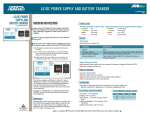
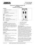
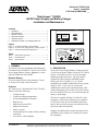
Section 61175043L2-5A
Issue 1, June 2000
CLEI Code # SIMPAADA _ _
Total Access™ 750/850
AC/DC Power Supply and Battery Charger
Installation and Maintenance
Contents
1. GENERAL ................................................................... 1
2. DESCRIPTION ............................................................ 1
3. INSTALLATION .......................................................... 2
4. SPECIFICATIONS ....................................................... 4
5. MAINTENANCE ......................................................... 4
6. WARRANTY AND CUSTOMER SERVICE .............. 4
GRN - OK
YEL - FAIL
RED - FAIL
OFF - FAIL
GRN - OK
YEL - DISCHARGING
RED - LOW
OFF - NOT CONNECTED
AC
BAT
9902271
Figures
Figure 1. TA 750/850 PS/BC, Front and Back ................... 1
Figure 2. AC/DC Power Supply Battery Charger Layout .. 3
Figure 3. Alternate Mounting Arrangements ...................... 3
1. GENERAL
This practice provides installation and maintenance
procedures for the ADTRAN™ Total Access 750/850
Power Supply/Battery Charger. Figure 1 is a front
and back illustration of the PS/BC.
Revision History
This is the initial release of this document. Future
revisions will be made in this subsection.
Features
The Total Access 750/850 PS/BC, P/N 1175043L2,
features include the following:
•
•
•
•
•
•
•
•
•
Compact design.
Versatile mounting arrangements.
All mounting hardware included.
Built-in Fuse.
Multi-feature status LED.
Modular connections.
Positive ground.
Uninterrupted power output if battery backup
connected.
FCC and UL 1950 compliant.
61175043L2-5A
120 VAC/
2A 60HZ INPUT
THIS UNIT MAY BE
POWERED BY 2
SOURCES. DISCONNECT
BOTH SOURCES BEFORE
SERVICING.
3 AMP
1175043L2
-48V ,
2A INPUT
-54V ,
2A OUTPUT
AC ALARM
OUTPUT
S
FU
E
Tables
Table 1. Alarm Relay Operation ........................................ 2
Table 2. LED Indication .................................................... 2
Table 3. Specifications ....................................................... 4
1175043L2
Figure 1. TA 750/850 PS/BC, Front and Back
2. DESCRIPTION
The AC/DC Power Supply/Battery Charger provides
-54 VDC to the Power Supply Unit in the TA 750/850
Chassis. The PS/BC receives 115 VAC through a
standard plug and wall socket. The unit works in
conjunction with an optional ADTRAN backup
battery pack, P/N 1175044L1, L2, L3. In this
arrangement, the PS/BC maintains the battery at peak
charge of -54V. If AC power is lost, the unit
automatically transfers power from the battery pack
without interrupting service. When AC power returns,
the unit switches back to AC power and recharges the
battery to peak charge.
This device complies with Part 15 of the FCC rules.
Operation is subject to the following two conditions:
(1) This device may not cause harmful interference,
and (2), this device must accept any interference that
may cause undesired operation.
Changes or modifications not expressly approved by
ADTRAN could void the user’s authority to operate
this equipment.
Trademarks: Any brand
names 61175043L2-5,
and product names
included
Section
Issue
1 in this document are
trademarks, registered trademarks, or trade names of their respective holders.
1
Alarm and Battery Disconnect Relays
Two relays support Power Supply operation:
• Alarm relay
• Battery disconnect relay
ALARM RELAY AND ALARM SIGNAL
The Alarm relay is provided for customer use. In
normal operation the contact alarm relay is open. If
an AC power failure occurs and the unit defaults to
the battery backup, the relay will cycle open/closed
once per second (that is one second open then one
second closed). The tolerance on this cycle time is
25 percent.
This indicates the battery is discharging in support of
the load. If battery voltage decreases to 45V the relay
stays closed to indicate the battery is becoming
depleted. The relay will open automatically when
normal AC voltage is restored. Table 1 summarizes
alarm relay operation.
Table 1. Alarm Relay Operation
Condition
Alarm Relay
Normal
Open
AC Power Failure/Battery
Backup engaged
Battery voltage is less than
40V
Cycles open/closed once
per second
Stays closed
An alarm signal that cycles synchronously with the
alarm relay is provided on the output cable. This
signal, which is open during normal operation, cycles
between open and ground during battery backup
(as described for the alarm relay), and is ground when
the battery voltage falls below 45V.
BATTERY FAIL ALARM
For battery backup systems that employ the optional
Battery Test Assembly (P/N 1175044L3) an alarm
signal is provided to the TA 750/850 L2 Power
Supply that indicates a failed battery (in need of
immediate replacement). This signal is passed to the
Alarm Relay and Output Alarm Signal. When a failed
battery is detected, it is indicated by the Alarm Relay
cycling open for 450 ms, then closed for 450 ms.
Battery failure is also indicated by the output alarm
signal cycling open to ground at the same rate.
BATTERY DISCONNECT RELAY
The battery disconnect relay disconnects the battery
pack from the system if the battery voltage falls below
40 VDC. This feature prevents damage to the
2
batteries. The batteries will be recharged when normal
AC voltage is restored and the relay will close when
the battery voltage exceeds 40V.
Certain alarm features on the power supply are still
powered by the battery after the disconnect relay is
opened. These features slowly drain the battery. If it
is known that AC power will be unavailable for an
extended period (greater than a week), ADTRAN
recommends that the battery be disconnected from the
power supply to prevent over-discharge.
The batteries used in ADTRAN’s battery backup
system are designed to withstand occasional
over-discharge. While it is not recommended, the
batteries can recover their full capacity under normal
charging conditions, even when they have been
subjected to extreme over-discharge.
Fuse
A 3-amp fuse on the back panel protects the unit from
over current. The fuse isolates the AC input from the
power supply in the event of a fault. The fuse is
replaced by twisting the black cap to the left and
pulling the fuse out. After the new fuse is inserted,
the cap is pushed back in and turned to the right.
Status LED
A single multi-feature LED on the front panel
provides AC operation or battery operation power
status. Refer to Table 2 for indication descriptions.
Table 2. LED Indication
AC Power
Operation
Green OK
Battery
Operation
Green OK (charging)
Yellow Power Fail
Yellow Discharging
Red Power Fail
Red Low (<40V)
Off Power Fail
Off Disconnected
3. INSTALLATION
C A U T I O N !
SUBJECT TO ELECTROSTATIC DAMAGE
OR DECREASE IN RELIABILITY.
HANDLING PRECAUTIONS REQUIRED.
After unpacking the unit, inspect it for damage. If
damage is noted, file a claim with the carrier then
notify ADTRAN Customer Service.
Section 61175043L2-5, Issue 1
61175043L2-5A
There are three installation arrangements:
• Wallmount.
• Mounted to TA 750/850 chassis.
• Mounted to backup Battery Pack (L1 only).
Wallmounting
For the wallmount arrangement, the PS/BC is
normally installed on the designated 3/4-inch or
thicker plywood with four #6 by 3/4-inch
flat-head wood screws.
Refer to Figure 2. Installation is as follows:
Optional Mounting Locations
As an optional installation arrangement, the PS/BC
unit can mount on either side of the TA 750/850
chassis, or the top of the battery pack (wall or rack
orientation) which has space for two PS/BCs. These
locations all have pre-threaded inserts designed for the
PS/BC. For installation, four #6-32 by 3/8-inch
machine screws are provided.
CAUTION
When mounting to the battery pack, using
screws longer than 3/8-inch could damage
batteries.
1. Determine the preferred layout and ensure the
socket-outlet is located near the equipment and
easily accessible.
2. Ensure the unit is plumb then mark through the
four screw holes to identify where the pilot
holes will be drilled.
3. Using a 1/16-inch bit, drill pilot holes at the
marked locations.
4. Mount the unit using the pan-head screws.
5. Route and connect all cabling to the appropriate
device. Use cable tie-downs as needed.
6. Connect the ground stud using the most direct
route to a known equipment ground source.
-48 VDC Backup Battery Pack
TA 750
V.35
WARNING:
20 Hz FUSE
MUST BE REMOVED
BEFORE REMOVING COVER.
Terminal P2
LX IN
access
LY IN
coverEU2
T1
R1-I
T1-I
R-O
FT1
T-O
DC
POWER
1175044L1
BATTERY BACKUP
LX OUT
LY OUT
EU1
MLT-A
-48 R
MLT-B
-48ALM
MJ
MJR
-48 V
MJV
MJVR
MANAGEMENT
WARNING:
SCREW LENGTHS EXCEEDING 3/8"
MAY PUNCTURE BATTERIES
To Alarms
CAUTION
During TA 750 wall installation,
position the chassis so
front panels face up.
-54 VDC Output to TA 750
120 VAC/
2A 60HZ INPUT
AC/DC Power Supply
Battery Charging Unit
P/N: 1175043L2
THIS UNIT MAY BE
POWERED BY 2
SOURCES. DISCONNECT
BOTH SOURCES BEFORE
SERVICING.
-54V ,
2A OUTPUT
-48V ,
2A INPUT
AC ALARM
OUTPUT
3 AMP
-54 VDC Battery
Charging/Discharging Line
AC Power Input
Figure 2. AC/DC Power Supply Battery Charger Layout
61175043L2-5A
Section 61175043L2-5, Issue 1
3
Table 3. Specifications
Refer to Figure 3 for optional mounting arragements.
Electrical
BAT
1175043L1
GRN - OK
YEL - FAIL
RED - FAIL
OFF - FAIL
AC
GRN - OK
YEL - DISCHARGING
RED - LOW
OFF - NOT CONNECTED
2 AMP
2
A
M
P
OFF
ON
AC Input: 115 Volts nominal
Range: 88 to 132 VAC
DC Output: -54 Volts, 60 Watts average
100 Watts peak
Battery charging: 16 hr nominal, 24 hr maximum
Battery discharge: Up to 8 hours
Physical
1175043L1
BAT
GRN - OK
GRN - OK
YEL - FAIL
YEL - DISCHARGING
RED - FAIL
RED - LOW
OFF - FAIL
OFF - NOT CONNECTED
AC
Dimensions: 3 1/2" W x 1 3/4" H x 7" L
(including mounting tabs)
Weight: 1 lb. 8 Oz.
2 AMP
A
M
P
2
OFF
ON
Environmental
ON
2
A
M
P
3L1
504
117
- OK ING
- OK
GRN- FAIL
YEL - FAIL
RED - FAIL
OFF
GRN HARG
- DISCLOW D
YEL RED -CONNECTE
- NOT
OFF
2 AM
OF
Operating temperature: 0º to 50º C (32º to 122º F)
Storage temperature: -40º to 85º C (-40º to 185º F)
Relative humidity: 95% non-condensing
F
P
T
BA
AC
ON
2
A
M
P
3L1
504
117
- OK ING
- OK
GRN- FAIL
YEL - FAIL
RED - FAIL
OFF
GRN HARG
- DISCLOW D
YEL RED -CONNECTE
- NOT
OFF
2 AM
OF
F
P
T
BA
AC
years from the date of shipment if it does not meet its
published specifications or fails while in service
(see: ADTRAN Equipment Warranty, Repair, and
Return Policy and Procedure, document:
60000087-10A).
Contact Customer And Product Service (CAPS) prior
to returning equipment to ADTRAN.
Figure 3. Alternate Mounting Arrangements
For service, CAPS requests, or further information,
contact one of the following numbers:
Grounding
The ground connector on the PS/BC provides an
additional ground reference (the third prong of the
AC plug is also grounded) and may be connected to
“ground bus” or “ground wire” in a customer
equipment room. 18 AWG or larger ground wire is
recommended.
ADTRAN Sales
Pricing and availability
(888) 4-ADTRAN
4. SPECIFICATIONS
Refer to Table 3 for specifications.
Standard support hours:
Monday-Friday, 7 a.m. - 7 p.m. CST
5. MAINTENANCE
The AC/DC Power Supply/Battery Charger does not
require routine maintenance for design operation.
Emergency support: 7 days/week, 24 hours/day
ADTRAN does not recommend that repairs be
attempted in the field. Repair services are obtained by
returning the defective unit to ADTRAN Customer
Service.
6. WARRANTY AND CUSTOMER SERVICE
ADTRAN will replace or repair this product within 10
4
ADTRAN Technical Support
Presales Applications / Post-sale Technical Assistance
(800) 726-8663
ADTRAN Repair/CAPS
Return for repair / upgrade
(256) 963-8722
Repair and Return Address:
ADTRAN, Inc.
Customer and Product Support (CAPS)
901 Explorer Boulevard
Huntsville, Alabama 35806-2807
Section 61175043L2-5, Issue 1
61175043L2-5A