1
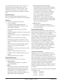
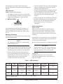
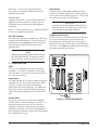
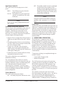
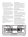
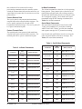
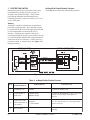
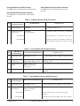
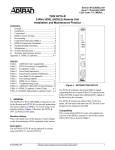
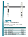
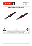
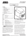
Section 61190860L1-5B
Issue 2, January 2002
CLEI Code: NCM5NTDD_ _
1xN Remote Protection Switch
Pro-Cap
Installation and Maintenance
CONTENTS
1. GENERAL ................................................................ 1
2. INSTALLATION ....................................................... 3
3. CONFIGURATION ................................................... 4
4. OPERATIONAL DESCRIPTION ............................. 5
5. NORMAL OPERATION ........................................... 6
6. PROTECT OPERATION ........................................... 6
7. PROTECTION SWITCH ........................................... 8
8. SWITCHBACK ........................................................ 10
9. AUTO-PROTECT OPERATION ............................ 11
10. SPECIFICATIONS .................................................. 12
11. MAINTENANCE ..................................................... 12
12. WARRANTY AND CUSTOMER SERVICE ......... 12
FIGURES
Figure 1.
Figure 2.
Figure 3.
Figure 4.
Figure 5.
Figure 6.
Figure 7.
1xN Pro-Cap .................................................... 1
SCIM Card Elements ...................................... 4
Normal Operation ........................................... 6
Arming Operation ........................................... 8
Protect Operation .......................................... 10
Switchover ..................................................... 10
Total Access 3000 Auto-protect Switching .. 11
TABLES
Table 1.
Table 2.
Table 3.
Table 4.
Table 5.
Table 6.
Table 7.
Table 8.
Table 9.
Table 10.
Figure 1. 1xN Pro-Cap
LED Indication ................................................ 3
In-Band Commmands ..................................... 7
Out-Of-Band Commands ................................ 7
In-Band Enable/Disable Protocol ................... 8
In-Band Protection Switch Protocol ............... 9
Out-Of-Band Enable/Disable Protocol ........... 9
Out-Of-Band Protection Switch Protocol ....... 9
In-Band Protection Release Protocol ............ 11
Out-Of-Band Protection Release Protocol ... 11
Specifications ................................................ 12
1. GENERAL
This practice provides installation and operational
procedures for the ADTRAN‚ Remote 1xN Pro-Cap
protection switch multi-mount housing (P/N
1190860L1). See Figure 1. Pro-Cap initiates remote
switching of a DS1 or HDSL circuit to a standby line
following detection of a fault. This eliminates the
immediate need for a vehicle dispatch to investigate
trouble or provide standby service. The shelf also
accommodates DDS and ISDN technologies but
without protection.
61190860L1-5B
Pro-Cap can be used in conjunction with the
ADTRAN Total Access® 3000 Carrier Class
Broadband Multiservice Access
Platform, or any standard Office Repeater Bay (ORB)
with T1 or HDSL to provide a Protection Switching
Network Interface (PSNI).
The Pro-Cap housing accepts eight T200 type circuit
cards or four dual slot T400 DS-1, HDSL, or HDSL2
circuit cards. The unit is a wall mounted assembly
that provides convenient access to CPE connections.
The assembly incorporates a circuit board backplane
that provides a choice of amphenol connector or
wire-wrap pins for facility wiring hook-up.
The Pro-Cap accepts -48 VDC local power or a
modular power supply that inserts into the POWER
slot at the far right of the shelf. The power supply
module includes an AC power cord that plugs into a
standard 110 VAC grounded outlet.
The Switch Customer Interface Module (SCIM) can
mount to either the left or right side of the Pro-Cap
housing to facilitate access to all CPE connections.
Trademarks: Any
brand names
and product names included
Section
61190860L1-5,
Issuein2this document are
trademarks, registered trademarks, or trade names of their respective holders.
1
The SCIM can be locally powered by -48 VDC, or
span powered from the standby unit in slot 8 if
equipped for span power. Slide switch S1 selects
between local or span power. CPE receive and
transmit connections are either amphenol or RJ-48C
jacks.
Revision History
Issue 2 adds Auto-Protect information when the
Pro-Cap is configured in a Total Access 3000 network.
Features
The 1xN Pro-Cap includes these features:
• Protection module.
• Compact and lightweight assembly that
accommodates eight T200 mechanics or four
T400 mechanics modules.
• Reversible SCIM for right side or left side
assembly.
• Prewired backplane to minimize wiring errors and
installation time.
• Protect module can function as standard channel
module.
• Dedicated slot for modular power supply.
• LEC facility connections are made by 25-pair
Amphenol XMT/RCV connectors or wire-wrap
pins.
• CPE connections are made to RJ-48C modular
jacks or 25-pair Amphenol XMT/RCV
connectors.
• Auto-Protect Switching with Total Access 3000
applications.
• Swing open tinted Plexiglas front cover.
• Available with key-locking metal cover (List 4
Option).
• Includes standard 10-year warranty.
Physical Description
The 1xN Pro-Cap consists of four elements:
1. Mounting-Plate
The mounting-plate attaches to a customer
premises backboard.
2. Shelf
The shelf has slots for seven channel modules,
one standby (protect) module, and one power
module, plus two external edge connectors for
the SCIM. The power terminal strip has
connections for power, alarm, and ground. The
shelf attaches to the mounting-plate.
2
3. Switch Customer Interface Module
This module inserts into one of the SCIM edge
connectors located on either side of the shelf. It
has both amphenol and RJ-48C interface
connections to the customer loop. Behind an
access panel is a power connection terminal
strip, a slide switch for either span or local
power, protect ON/OFF switch, and a
pushbutton for selecting individual module
protection or resetting the protect configuration.
Selection and status is indicated with associated
LEDs on the SCIM front panel.
4. Housing Cover
The Plexiglas swing door housing cover
encloses the shelf allowing viewing and access
to the shelf modules.
Functional Description
During normal customer and network transmission,
data is transported through the active modules in slots 1
through 7. The module in slot 8 is the standby
(protect) unit. If a fault is detected on an active line a
series of facility initiated manual commands switch the
standby module to an active mode in place of the
faulted unit. When the faulted unit malfunction is
resolved another series of manually initiated
commands (or the reset switch) returns it to active
service and the standby unit is returned to standby
status. The LED bank shows module status during
normal and standby conditions. When circuit
protection mode is disabled the Pro-Cap unit can be
used as a standard 8-slot T200 mounting.
Auto-Protect Switching
When the Pro-Cap is used in association with the
ADTRAN Total Access 3000 platform, certain Total
Access 3000 cards initiate an automatic protect
function with the Pro-Cap. These cards send the same
protect enable/disable, arming, and switching codes as
sent in the manual switching mode. The Pro-Cap does
not require configuration changes to support the
auto-protect feature. The same configuration
supporting manual switching also supports automatic
switching. Additional information is in Section 9 of
this practice.
Listed here are Total Access 3000 cards that initiate the
auto-protect codes:
• H2TUC 1181112L5
• H2TUR 1222026L7
• H2TUR 1221026L7
Section 61190860L1-5, Issue 2
61190860L1-5B
Documentation associated with the listed cards
provides information on implementing the auto-protect
function.
LED Indication
Table 1 describes LED indication.
• All LEDs OFF indicates no power to the SCIM.
• All LEDs flashing red indicates the protect card is
disabled and SCIM power is local -48 VDC.
2. INSTALLATION
C A U T I O N !
SUBJECT TO ELECTROSTATIC DAMAGE
OR DECREASE IN RELIABILITY.
HANDLING PRECAUTIONS REQUIRED.
3. The shelf assembly lifts away from the mountingplate by disengaging the chassis tabs from the
mounting-plate support hooks.
4. Using the mounting-plate as a template, position
the mounting-plate at the desired location and
mark four pilot holes. Ensure the unit is level and
that cable plugs will reach their designated
sockets.
5. Using an appropriate bit, drill the four pilot holes.
6. Align the mounting-plate to the pilot holes and
attach to the wall with appropriate fasteners.
7. Reassemble the unit by reversing steps
1 through 3.
Cable Connections
After unpacking the unit inspect it for damage. If
damage is noted, file a claim with the carrier then
notify ADTRAN. Refer to Warranty and Customer
Service.
Mounting Procedure
The 1xN Pro-Cap installs at the remote location using
the following procedure:
NOTE
All component fasteners are spring-loaded,
captured thumb screws.
1. Remove the housing from the shelf by unscrewing
the two thumb screws on the side of the housing.
The housing pulls out and away from the shelf.
2. Remove the shelf from the mounting-plate by
unscrewing the thumb screw at the top center of
the shelf bay. It is not necessary to remove the
SCIM assembly unless its position is to be
reversed to the other side of the shelf.
Frame Ground
Both the shelf and SCIM have separate ground
connections. Each must be connected to a known
approved ground location. Verify metal to metal
contact on all connections and ensure ground circuit
continuity.
The shelf has various openings for wire route options
along with tie-wrap anchor points and extrusions for
securing cables and connectors.
Specific wiring arrangements are customer developed.
CAUTION
Transmit and receive loops to both facility and
CPE have two connection schemes. Only one
connection method is to be used, not both.
Facility Side
Amphenol Connection – The to-facility and
from-facility amphenols can be either left-side or
right-side oriented.
Table 1. LED Indication
Slot LED
OFF
Flash Green
Solid Green
Flash Red
Solid Red
Flash Red/Green
1-7
Protect
Deselected
Request to
Protect Enable
Protect
Enabled
Protect Card
Disabled**
In Protect
Mode*
N/A
8 PROT
No Network
Signal
Protect
Activated
Protect In
Standby
Protect Card
Disabled**
N/A
Protect Card Armed
FAIL
Protect
Operational
N/A
N/A
Protect Card
Disabled**
Protect Failure
N/A
* Only one module at a time in slots 1 through 7 can be in Protect Mode.
** Protect switch S3 OFF.
61190860L1-5B
Section 61190860L1-5, Issue 2
3
Wire-Wrap – The to-facility and from-facility
wire-wraps are an alternate method in lieu of the
amphenol connections.
Customer Side
Amphenol Connection – The to-CPE and from-CPE
amphenols should be left-side oriented to prevent
SCIM panel removal interference after amphenol
installation.
RJ-48C – These modular jacks are an alternate method
in lieu of the amphenol connections.
-48 VDC Terminal
Local DC power connects to terminal strip TB1 at the
bottom of the shelf backplane. This power source is
distributed across the backplane to slots 1 through 8
and can jumper to the SCIM TB1 to power the
controller card.
Shelf Cards
Channel cards are individually configured to meet
network or customer requirements. Certain cards only
receive power from network span power. These cards
do not have pin contacts for shelf power.
CAUTION
It must be determined if channel cards can receive
both span power and shelf power. Some cards
may malfunction under that condition.
SCIM Controller Card
Option switches on the SCIM controller circuit board
are located behind an access panel. Remove the
housing from the shelf to gain access to the panel’s
thumb screw fastener (refer to Step 1 of the Mounting
Procedure). See Figure 2 for SCIM Card connections,
terminals, indication, and switches.
NOTE
Both the shelf backplane and the SCIM card each
have a TB1 terminal strip. This practice identifies
the specific TB1 when referenced in the text.
3. CONFIGURATION
Shelf
There are no configuration selections on the shelf
backplane. If -48 VDC is connected to TB1 on the
shelf card there is no need for the power card unless
for a spare power source.
Power Card
The PWR card has an AC power cord that inserts into
a standard 110 volt AC grounded wall outlet. When
AC power is in use, local power should not be
connected to TB1 on the shelf card. The PWR card
also applies power to the same TB1 shelf terminals,
which in turn can be jumpered to TB1 on the SCIM
card.
Protect Card
The protect card can receive power from either the
network (span) or from the backplane (-48 VDC). To
initiate the protect feature the card in slot 8 must
support the technology of the channel cards that are
enabled for protection. The protect card should also
have span power capability to power the SCIM should
that configuration be used.
4
Figure 2. SCIM Card Elements
Section 61190860L1-5, Issue 2
61190860L1-5B
Span Power Switch S1
This switch selects between span power or local
power.
SPAN –
The SCIM receives power from the
protect card in slot 8.
LOCAL – The SCIM receives power from local
-48 VDC to terminal strip TB1 on the
SCIM card.
NOTE
Local -48 VDC can be jumpered from the shelf
TB1 terminals.
Protection Select/Reset Switch S2
The first function of this pushbutton switch enables or
disables standby protection for individual slots (1
through 7). Protection for selected slots can be
disabled if cards of a different technology occupy
those slots, or to meet SLA agreements. Protection is
selected using the following procedure:
1. Depress S2 for 5 seconds. Slot 1 LED will start to
flash green; all other LEDs will be OFF. Release
S2.
2. To enable protection for slot 1, press and release
S2. Slot 1 LED will turn solid green and the LED
for slot 2 will begin to flash.
3. To pass over a slot that is not to be protect
enabled, wait several seconds while that slot’s
LED is flashing. The LED turns OFF and the next
LED begins to flash green.
4. Continue this process until the LEDs for all slots
designated for protection are ON.
The protect configuration, once established, is
maintained in memory.
The second function of this switch is to reset the
protect configuration in the event the protect card was
enabled to temporarily replace a malfunctioning shelf
card. After the system is returned to normal,
depressing S2 for a minimum 5 seconds resets the
protect configuration stored in memory. Immediately
release the pushbutton when the LEDs return to the
protect configuration.
Protect Switch S3
This switch controls the protect feature.
ON – All standby and protect functions are active.
61190860L1-5B
OFF – The standby module in slot 8 is cut through
and detection circuitry disabled. If the
standby card was supplying span power to
the SCIM, all the LEDs will be OFF. If the
SCIM was receiving local -48 VDC power,
all the LEDs will flash red.
NOTE
The protect card in slot 8 should have span power
capability either permanent or as an enabled
option.
Local Power
Terminal strip TB1 on the SCIM card accepts local -48
VDC power. Installation requires that wiring (14 to 26
AWG) be routed from the back of the SCIM housing.
This arrangement is an alternative to span power the
SCIM receives from the protect card. Slide switch S1
selects between span power or the -48 VDC supply.
SCIM frame ground is attained through a separate
ground terminal.
4. OPERATIONAL DESCRIPTION
The SCIM card is a component of the Pro-Cap
assembly that provides T1 drops to the customer
through an RJ-48C or Amphenol connector. The T1
1x7 Controller Card is an enhanced SCIM that also
performs manual 1x7 protection switching on T1
(HDSL) services. The controller card is designed to
function as a manual protection switch and does not
have the capability to address an automatic protection
switch function.
T1 protection switching is accomplished through two
network elements:
• Central Office Element (COE)
• Remote Element (RE).
The COE functions as the master of the protection
switching operation by initiating all commands. The
RE will only respond to the COE commands. The
controller card and a Network Interface Unit (NIU)
represent the RE. A Digital Test Access Unit (DTAU),
a Digital Cross-connect, or a T1 Test Set can represent
the COE.
The controller card uses the card in slot 8 of the
Pro-Cap mounting as the standby service. The NIU in
slot 8 will provide the appropriate physical layer
interface to the network (i.e. HDSL2, HDSL, or T1
AMI) and 4-Wire T1 AMI physical layer interface to
Section 61190860L1-5, Issue 2
5
the controller card. The controller card will
continuously monitor the network receive T1
transmission service in slot 8 (i.e. standby line) for
commands. Upon the receipt of these commands, the
controller card will initiate the T1 service switchover
from the requested line (1 through 7) to the standby
line. The controller card when optioned for protect
will conduct the following:
1. Monitor the incoming network signal to
determine if the protect line is operational. If the
line is operational the FAIL LED will be OFF. If
no signal is present, the slot 8 PROT LED will be
OFF and the FAIL LED will be ON.
2. Provide a loopback to the network as long as a
transmit signal is not present from the CPE. If a
signal is placed on the slot 8 CPE transmit to the
network, the loopback will be released and
normal transmission to and from the network can
occur. Upon removal of the transmit signal,
loopback will be activated.
The SCIM controller card can be locally or remotely
provisioned to either enable or disable slot-switching
capability. If a slot is protect enabled, when a switch
request for that slot is received on the protect channel,
the slot will switch. If the slot is protect disabled, it
cannot be switched.
5. NORMAL OPERATION
Data is transported from the network to the customer
through an assigned slot (slot 1 through slot 7). The
standby line is transported through slot 8
(see Figure 3).
Normal Receive Path
The receive path is non-protected and transformer
coupled between the network and the customer. The
receive path is monitored for in-band or ESF
bit-patterned datalink messages. The receive path
toward the network will be terminated with a 100 ohm
resistor. This 100 ohm termination increases the
reliability of T1 signal recovery and minimizes
crosstalk. The receive path toward the customer will
be an open termination.
Normal Transmit Path
The transmit path is non-protected and transformer
coupled between the network and the customer.
Passive Mode
The controller card can be configured to establish a
passive transmission path by detecting a T1 signal from
the customer. The transition from normal to passive
mode will require the loopback to the network removed
and the receive path to the customer to be reconnected.
Passive Mode to Normal Operation
The controller card will return to normal operation by
detection of a loss-of-signal from the customer.
6. PROTECT OPERATION
Protect operation is defined as the transport of data
from the network to the customer using a standby line
connected to Slot 8. Communication between the COE
and RE will be based upon in-band or out-of-band
(ESF datalink) commands. Upon detection of a fault
on an active line, the controller card will not
automatically switch the customer’s data onto the
standby line. A remote provisioning command must be
used to switch the customer’s data onto the standby
line. Once the customer’s data is on the standby line,
CENTRAL OFFICE
CUSTOMER PREMISES
Office
DTWA
Repeater
DSX-1
Bay
NIU
< Live Traffic >
or
CIM
Main
Office Repeater
CPE
< Live Traffic >
HTU-C
DCS
T1
T1 / HDSL / HDSL2
Office Repeater
Standby
or
Idle >
HTU-C
Idle >
WECO D4
WESCOM 3192
NORMAL OPERATION
Figure 3. Normal Operation
6
Section 61190860L1-5, Issue 2
61190860L1-5B
this condition will be locked until a remote
provisioning command orders the controller card to
switch the customer data back onto the main line, or a
signal failure of greater than 30 seconds occurs on the
protect Slot 8.
Protect Receive Path
The receive path is non-protected and transformer
coupled between the network and the customer. The
receive path is monitored for in-band or ESF
bit-patterned datalink messages. The receive path will
be a passive transmission path.
Protect Transmit Path
The transmit path is non-protected and transformer
coupled between the network and the customer. The
transmit path will be a passive transmission path.
In-Band Commands
The in-band commands are based on a 16-bit repeating
binary pattern. These patterns were selected to avoid
random data replication and yellow alarm generation.
In-band code qualifications involve receiving the codes
for 5 contiguous seconds. The in-band codes can be
transmitted using SF/ESF framing or unframed. See
Table 2 for in-band commands.
Out-of-Band Commands
The out-of-band commands are based on the ANSI
T1.403-1995 standard on T1 protection switching.
ANSI T1.403-1995, Table 4, specifies the command
and response messages for T1 protection switching.
Out-of-band code qualifications involve receiving the
codes for greater than 4 consecutive messages. See
Table 3 for out-of-band commands.
Table 3. Out-Of-Band Commands
Table 2. In-Band Commands
Command
Hex
Pattern
Binary Pattern
Command
Hex
Pattern
Binary Pattern
Switch Arming
18FF
0001 1000 1111 1111
Switch Arming
C440
1100 0100 0100 0000
Slot Enable
78FF
0111 1000 1111 1111
Slot Enable
C540
1100 0101 0100 0000
Slot Disable
7AFF
0111 1010 1111 1111
Slot Disable
C640
1100 0110 0100 0000
Switch Release
26FF
0010 0110 1111 1111
Switch Release
C44F
1100 0100 0100 1111
Switch Activation
Code
Reset
24FF
0010 0100 1111 1111
Switch Activation
Code
Line 1
C441
1100 0100 0100 0001
Line 1
42FF
0100 0010 1111 1111
Line 2
C442
1100 0100 0100 0010
Line 2
44FF
0100 0100 1111 1111
Line 3
C443
1100 0100 0100 0011
Line 3
46FF
0100 0110 1111 1111
Line 4
C444
1100 0100 0100 0100
Line 4
48FF
0100 1000 1111 1111
Line 5
C445
1100 0100 0100 0101
Line 5
4AFF
0100 1010 1111 1111
Line 6
C446
1100 0100 0100 0110
Line 6
4CFF
0100 1100 1111 1111
Line 7
C447
1100 0100 0100 0111
Line 7
4EFF
0100 1110 1111 1111
61190860L1-5B
Section 61190860L1-5, Issue 2
7
7. PROTECTION SWITCH
Remote provisioning for a protection switch can be
accomplished by sending a specific sequence of
in-band or out-of-band messages. These remote
provisioning commands are transmitted to the
controller card from a remote test facility or a T1 test
set at a DSX panel.
In-Band Slot Enable/Disable Protocol
See Table 4 for in-band slot enable/disable protocol.
Arming
Arming the controller card prevents an inadvertent
protection switch operation. The controller card can
be armed with the presence of the appropriate in-band
or out-of-band pattern on the network receive
interface. Disarming the controller card can be
accomplished with the presence of an in-band (11100)
or out-of-band (ESF datalink) NIU loop down pattern
on the network receive interface, a 1-hour time out, a
protection switch, or a manual reset. See Figure 4 for
arming activation.
CENTRAL OFFICE
CUSTOMER PREMISES
Office
DTWA
Repeater
DSX-1
Bay
NIU
Office Repeater
< Live Traffic >
CIM
Main
CPE
< Live Traffic >
or
HTU-C
DCS
T1
< Arming Code >
T1 / HDSL / HDSL2
Office Repeater
or
Standby
< Arming Codes >
HTU-C
WECO D4
WESCOM 3192
TEST
ARMING OPERATION
Figure 4. Arming Operation
Table 4. In-Band Enable/Disable Protocol
Step
8
COE In-Band
Command Patterns
In-Band Pattern
Controller Card
1
Send Arming Code
C440 Hex
Loopback the Arming Code.
2
Send Slot Enable or
Disable Code
C540 Hex Enable
C640 Hex Disable
Loopback the Enable/Disable code for 5 Sec, then
No Sync for 5 Sec. Repeat until pattern is
removed.
3
Send Protection Line
Switch C44X where X
= line number
C44X Hex
X = Line Number
4
Remove Pattern
Loopback the C44X code where X = line number
for 5 Sec., then No Sync for 5 Sec. Repeat until
pattern is removed.
Slot is now Enabled or Disabled for protection
switching.
Section 61190860L1-5, Issue 2
61190860L1-5B
In-band Protection Switch Protocol
See Table 5 for in-band protection switch protocol.
Out-of-Band Protection Switch Protocol
See Table 7 for out-of-band protection switch
protocol.
Out-of-Band Enable/Disable Protocol
See Table 6 for out-of-band slot enable/disable
protocol.
Table 5. In-Band Protection Switch Protocol
Step
COE In-Band
Command Patterns
In-Band Pattern
Controller Card
1
Send Arming Code
C440 Hex
Loopback the Arming Code.
2
Send Protection Line
Switch Code
C44X Hex
X = Line Number
Loopback the C44X code where X = line number.
Slot Enabled
Perform switchover 5 seconds later. Loss of sync.
Slot Disabled
Continuous Loopback of the C44X code where X
= line number. No switchover and no loss of sync.
Table 6. Out-Of-Band Enable/Disable Protocol
Step
COE In-Band
Command Patterns
Bit-Oriented Datalink Pattern
Controller Card
1
Send Arming Code
0001 1000 1111 1111
Loopback Arming Code for 400 ms followed by AIS.
2
Send Slot Enable or
Disable Code
Enable 0111 1000 1111 1111
Disable 0111 1010 1111 1111
Loopback the Enable/Disable code for 400 ms
followed by AIS.
Send Protection Line
Switch
0100 XXX0 1111 1111
XXX = Line Number
(see Table 3)
Loopback line # code for 400 ms followed by AIS.
3
4
Remove Pattern
Slot is now Enabled or Disabled for protection
switching.
Table 7. Out-Of-Band Protection Switch Protocol
COE In-Band
Command Patterns
Bit-Oriented Datalink Pattern
1
Send Arming Code
0001 1000 1111 1111
Loopback Arming Code for 400 ms followed by AIS.
2
Send Protection Line
Switch Code
0100 XXX0 1111 1111
XXX = Line Number
(see Table 3)
Loopback line # code:
Step
61190860L1-5B
Controller Card
Slot Enabled
Perform switchover after 4 consective messages
received.
Slot Disabled
Loopback line # code followed by AIS. No switchover.
Section 61190860L1-5, Issue 2
9
See Figure 5 and Figure 6 for switchover codes
and traffic results.
NOTE
Communication using in-band codes will override
the customer’s data during the switchback
operation. The customer’s data will be overridden
for 10 seconds. These remote provisioning
commands are transmitted to the controller card
from a remote test facility or a T1 test set at a DSX
panel.
8. SWITCHBACK
Switchback operation is defined as the
re-establishment of the T1 transmission path between
the network and the customer using the regularly
assigned line. Communication between the COE and
RE will be based upon in-band or out-of-band (ESF
datalink) commands.
Switchback Receive Path
Remote
Switchback operation is accomplished by sending a
specific sequence of SF in-band patterns or ESF
datalink messages over the standby line.
Local
Depressing S2 on the SCIM card for a minimum 5
seconds resets the protect configuration in memory.
CENTRAL OFFICE
DSX-1
< Live Traffic >
CUSTOMER PREMISES
Office
Repeater
Bay
DTWA
NIU
Office Repeater
or
HTU-C
DCS
< Acknowledge
Switch Code >
CPE
< Live Traffic >
T1 / HDSL / HDSL2
Office Repeater
or
HTU-C
CIM
Main
Standby
Switch Codes >
WECO D4
WESCOM 3192
TEST
PROTECT OPERATION
Figure 5. Protect Operation
CENTRAL OFFICE
DSX-1
DCS
CUSTOMER PREMISES
Office
Repeater
Bay
DTWA
NIU
CPE
T1 / HDSL / HDSL2
< Live Traffic >
Office Repeater
or
HTU-C
CIM
Main
Office Repeater
or
HTU-C
Standby
< Live Traffic >
WECO D4
WESCOM 3192
TEST
SWITCHOVER
Figure 6. Switchover
10
Section 61190860L1-5, Issue 2
61190860L1-5B
In-band Release Protocol
See Table 8 for return to normal operation.
9. AUTO-PROTECT OPERATION
When the Pro-Cap is configured in a Total Access
3000 network optioned for the auto-protect feature, the
TA 3000 will re-map a failed loop's data to the TA
3000 protect unit which in turn sends the protect
initiate codes to the Pro-Cap. The Pro-Cap will put its
protect unit online to complete the standby
transmission loop to the customer. Loss of data
transmission on a particular loop for any reason
initiates the protect function. See Figure 7. Normal
transmission is automatically restored when the failure
is corrected.
Out-of-Band Release Protocol
See Table 9 for return to normal operation.
Signal Transmit
The controller card will transmit a 0 dB signal.
Line Build Out (LBO)
The controller card will not provide LBO functions.
The controller card will rely upon the NIU to provide
LBO.
Table 8. In-Band Protection Release Protocol
Step
COE In-Band
Command Patterns
1
Send switch release code
2
Remove pattern
In-Band Pattern
C44F Hex
Controller Card
Loopback Release Code. Perform switchback 5 seconds later.
Slot is returned to normal operation.
Table 9. Out-Of-Band Protection Release Protocol
Step
COE In-Band
Command Patterns
Bit oriented Datalink
Pattern
1
Send switch release code
0010 0110 1111 1111
2
Remove pattern
Controller Card
Perform switchback after 4 consecutive messages received.
Slot is returned to normal operation.
Total Access 3000
Pro-Cap
Remote
Units
H2TU-Cs
4
DS3
Feed
L2
MUX
3
2
1
D
C
B
A
R4
R3
CPE
R2
R1
Normal Operation
Auto-Protect Operation (Loop A Failure)
Figure 7. Total Access 3000 Auto-protect Switching
61190860L1-5B
Section 61190860L1-5, Issue 2
11
11. MAINTENANCE
The Pro-Cap does not require maintenance for normal
operation.
10. SPECIFICATIONS
See Table 10 for Specifications.
12. WARRANTY AND CUSTOMER SERVICE
ADTRAN will replace or repair this product within ten
(10) years from the date of shipment if it does not meet
its published specifications or fails while in service.
Refer to ADTRAN U.S. and Canada Carrier Networks
Equipment Warranty, document 60000087-10.
Table 10. Specifications
Specification
Physical Interface:
4-Wire
Signal:
T1 Bipolar
Coding:
AMI or B8ZS compatible
Framing:
SF, ESF, or Unframed
Line Rate:
1.544 Mb/s @ 50 ppm
Transmit Signal:
0 dB
Insertion Loss:
1.5 dB max at 772 kHz
Line Impedance:
100 ohms (± 20%) at 772 kHz
Maximum Detect Error
Rate:
< 10
Power:
Span Power at 57 to 63 mA
Local Power at ± 24 VDC to
56 VDC
-3
DC Voltage Drop (Span 24 VDC at 60 mA
Powered):
Operating Temperature:
Humidity:
-40° C to +65° C
Up to 95% noncondensing
UL Compliance:
FCC Compliance:
UL 1950 3rd Edition
FCC Part 15, Subpart B, Class
A Requirements
12
Contact Customer And Product Service (CAPS) prior to
returning equipment to ADTRAN.
For service, CAPS requests, or further information,
contact one of the following numbers:
ADTRAN Sales
Pricing/Availability
(800) 827-0807
ADTRAN Technical Support
Pre-sales Applications/Post-sales Technical Assistance
(800) 726-8663
Standard hours: Monday-Friday, 7 a.m. - 7 p.m. CST
Emergency hours: 7 days/week, 24 hours/day
ADTRAN Repair/CAPS
Return for Repair/Upgrade
(256) 963-8722
Repair and Return Address
ADTRAN, Inc.
CAPS Department
901 Explorer Boulevard
Huntsville, Alabama 35806-2807
Section 61190860L1-5, Issue 2
61190860L1-5B