1
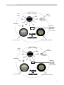
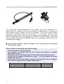
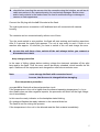
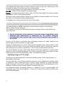
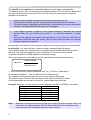
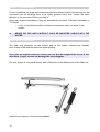
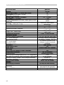
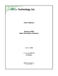
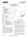
user manual 3/2010 1 Register CONTROL PANEL........................................................................................................................................... 3 POWER SUPPLY – CHARGING EXTERNAL ACCUMULATOR..................................................................... 4 START-UP ....................................................................................................................................................... 5 PILOT LAMP / VIDEO MODE (FUSION)......................................................................................................... 6 AUTOMATIC TTL MODE ON ANALOGUE CAMERAS ......................................................................................................................................................................... 6 MIXED LIGHT PHOTOS .................................................................................................................................. 7 AUTOMATIC TTL MODE ON DIGITAL CAMERAS ........................................................................................ 7 MANUAL POWER STEPS............................................................................................................................... 8 PROTECTION AND CARE .............................................................................................................................. 9 CABLE – CONNECTIONS............................................................................................................................. 10 FLASH ARM CONNECTOR .......................................................................................................................... 10 FORM UP THE FLASH CAPACITOR ........................................................................................................... 11 TTL- CHECK ................................................................................................................................................. 11 LEAKAGE ON THE HOUSING...................................................................................................................... 11 SAFETY INSTRUCTIONS.............................................................................................................................. 12 IMPORTANT NOTES FOR DIVING TRIPS.................................................................................................... 12 MALFUNCTIONS / POSSIBLE CAUSES / POSSIBLE SOLUTIONS............................................................ 13 WHAT TO DO IN THE EVENT OF DAMAGE?.............................................................................................. 13 TECHNICAL DATAS PRO160........................................................................................................................ 14 TECHNISCHE DATEN FUSION..................................................................................................................... 15 WARRANTY................................................................................................................................................... 16 SERVICE-ORDER.......................................................................................................................................... 17 SERVICE-ADDRESS...................................................................................................................................... 18 SERVICE-ORDER.......................................................................................................................................... 19 KONTAKT ..................................................................................................................................................... 21 2 control panel modeswitch pilot push button ready lamp version TTL= analogue Ixx = I-TTL Exx = E-TTL Oxx = Olympus Pro160 by subtronic accu connector synchronous connector modeswitch pilot push button ready lamp version TTL= analog Ixx = I-TTL Exx = E-TTL Oxx = Olympus Fusion by accu connector subtronic synchronous connector 3 power supply – charging external accumulator The revolutionary lithium-manganese-cells are reliably, robust and harmless. On a malfunctioning f.e. collapse of a cell by overloading or by aging there is no danger of a lithium cobalt reaction (metallic fire like an explosion). These most modern lithium accumulator technology allows the construction of a very safe, small and high performance external accu system, which is included in the lightning arm. These cells have a substantially higher power density than NiMh cells and need therefore less place and safv weight. They have no MEMORY effect. The accumulator haven't need to be unloaded before charging. insert the S4 connector from the charger in the connector from the external accumulator system. Please consider the following points while loading: • • • • • Load if possible at room temperature. don't storage the charger and the accu before and during the charging procedure in the sun. At temperatures over 40°C and under 0°C the achievement of the accu sinks. As soon as the charger-LED switched to „green “, you can separate the battery charger from the accu. In the case of use of other battery chargers the accumulator can be damaged. Use therefore only the battery charger supplied by us. mode indicator orange green 4 function quick charging top off charge Time aprox. 2 h start-up check before inserting the camera into the camerahousing the hotshoe, as well as all cable connections in the camerahousing for mechanical damages. Broken wires and/or bad contacts in the feeder lines can lead to malfunctionings or damage to camera or flash appartuses. Connect the S4 plug with the left S4 socket at the flash. The right synchronous connection is N5 bulkhead and will connected with camera housing. The contacts can be connected easily without use of force. Turn the mode switch in auto position. the flash will start working and load the capacitors. After 2-3 seconds the ready light appears. The unit is now ready to work. If there is no reaction after approx. 10 seconds, you have to switch of the unit and charge the accu. to save the unit from a loss, switch off the unit always before you connect or disconnect accu-tank. deep charge protection In the case of falling voltage below working voltage the electronic switches off the pilot lamp and/or the flash. Thus the accu cannot be deeply unloaded, which benefits the life span. Switches off the equipment and charges the external accumulator soon. Note: never storage the flash with connected accu! be sure, that the accu is charged before storaging. Over temperature protection your pro160 is fitted with a thermal protection circuit. If the temperature in the unit is higher than the allowed operating temperature f.e. by to short flashcycles ore other negative impacts, the processor will switch off the high voltage circuit immediately. In this case the ready indicator on the backplate starts blinking. On analogical flashes the ready indicator in the camera blinks too. The flash do not fire during this process. If the temperature in the unit in the allowed area the flash restarts immediately 5 Pilot lamp / Video mode (Fusion) The installed pilot lamp allows a better orientation during a night dive. Similarly this LED illuminate the object for autofocus and the cameradisplay . To start the pilot lamp push the pilot button on the rear of your flash. Pro160: to switch off the lamp push the button again. Fusion : to change from pilot to video mode, push the button again. the fusion changes from approx. 20% to 100% lightning power . During the video mode the flash function is not available, this feature allows you to use the lamp also for photos with ambient light and lamp. To change back in flash mode push the pilot button again. automatic TTL mode on analogue cameras The flash identifies in AUTO- mode the connected camera system automatically. (Nikon, Canon, Pentax. analogue ) The ttl-sensor is mounted in the camera and gives a switch-off pulse to the flash if the exposure is OK. • For the correctness of the exposure is now the camera responsible, as the delivered light achievement is determined by the camera. Therefore manipulations of the exposure can in this mode of operation only be made at the camera. As soon as the flash is connected with a analogical camera, the ready symbol in the camera lights up after touching the trigger lightly. Strongly reflecting objects as well as back light photographs nearly always lead to under exposure in the TTL mode. Use for this cases the manual mode or correct the exposure index adjuster of the camera in positives (+). Do not forget resetting after shooting. The same problem you have when using extreme wide angle objectives, if relative small object is in front of a dark background. The sensor recognizes in this case mainly the dark background and turns-off the flashlight to late. Overexposures results. operating range on TTL-mode According to the selected aperture arises the operating range, which depends also on the turbidity under water. The best aperture in the different situations depends on the needed reach and the depth of sharpness. With smaller becoming f number (larger opening) the depth sharpness range is reduced. Use a small f-number, where the background is to be illustrated in a dif fuse way. for Macro shoots normally higher f-numbers were used. For standard situations a midrange aperture, f.e. aperture 5,6 to 8 is recommended. The operating range in this case is approx. 2 meters (6,5 feet) which might be sufficient for most UW photographs. 6 mixed light photos In small depths, the daylight is enough, in order to expose the film correctly. But the colors disappears, beginning with red, to yellow, etc. Flashes are only necessary to receive colours with increasing depth. The substantial on mixture light photographs is an easy underexposure, related to the ambient brightness. Example: Exposure indicator on the camera, measured horizontal in the water : F 8 Aperture adjustment on the camera in A- or M - mode : 11 or 11/16 Thus the flash must brighten up a flashed object around approximately 1 to 2 apertures, the colour of the water is in this case deep blue. You can use the manual powersteps also for mixed light photos. automatic TTL mode on digital cameras The flash works only with integrated or external digital converter (f. e. HeinrichsWeikamp) in TTL- mode with digital cameras. In the opposite to analogical cameras digital cameras are not identified automatically by the flash electronic, because of the different interfaces from the camera brands. for correct function a digital converter is absolutely necessary. Depends on the underwater housing manufacturer or model, the converter is already integrated to the camera housing. Please ask therefore your the manufacturer or your local dealer. operation with external converter Connect the digital converter (as written in the manual) between the camera-housing and the flash. Turn the function mode switch in “Auto” position. In this mode the flash is fully controlled by the connected camera system. (see also analogical TTL- mode ) Note: there is a permanent data transfer between the camera and the flash. operation with integrated converter Connect the synchronous cable to the camera housing. Be sure, that all needed pins are connected between the hotshoe and the plug outside the housing. ( Nikon needs 5 wires, Canon need 6 wires for TTL) Basics to digital TTL: Your camera needs for the ttl–mode one or more short preflashes. The reflected light on the sensor is the basement for the calculation of the main flash. The precision of this calculation depends on the speed of the camera, the quality of the system, the function-mode you use. Please read the manual of the camera for more informations. Note : never use the red eye flash mode 7 manual power steps The Pro160 and the fusion with integrated digital converter have a automatically TTL/Manual switch. The unit changes automatically between TTL and manual, depends of the main functionswitch on the rear of the unit. By using the manual power steps the preflash is switched-off. together with an digital camera without using an converter only the “synchronous” and the “ground” contact must be connected with the camera. For malfunctions or damages by another kind of connections or wrong connections subtronic excludes liability and/or payment of damages. if the digital converter is build-in in the camera housing or between the camera and the flash unit, you should only use the ¼ - or, with slow cameras, ½ power step. As your flash triggers to all signals ( also preflashes ) in the case of an full flash the capacitors inside the flash are empty after the first shoot and have not enough energy to expose your picture. please read in the manual of your camera whether your camera supports manual flashes. functionality : the flash delivers in manual mode a constant lightning energy. These power steps are controlled by the integrated computer and therefore every time identical. The energy depends only one the position of the main function switch. 1 equates full power and 1/32 equates the smallest energy The correct aperture for the camera can be calculated with the following formula. Guide number Aperture = Distance in m This formula is only valid for distances over 1m ( 3,28 feet ) under water. In the manual position “1” the unit delivers its full achievement. The gradation of the power steps amounts to one aperture each step. The power output of the unit can be reduced thus around maximally 6 steps. So the appropriate screen can be found for mixture lights and close-ups. Example: distance 1 m (2m way of the light) (depends on DIN21/100ASA, clear water) mode switch 1 1/2 1/4 1/8 1/16 1/32 Note: 8 camera f-number 16 11 8 5.6 4 2.8 Because of the larger illuminating angle over water you receive values, which are more then one aperture higher than the above table data for underwater when measurements with a lightning exposure meter ashore. protection and care All parts of the unit are build in anodized seawater resistant aluminium or plastic. It is recommended anyway, to wash the unit after a saltwaterdive with fresh water. This is particularly valid for the operating board. The synchronous cable should be removed only after rinsing from the camera. NEVER DIP THE EQUIPMENT WITHOUT CAP ON THE SYNCHRONOUS PLUGS INTO THE WATER change of the seal-rings We recommend to send the unit back to us for service after approx. 5 years, for changing the seal-rings. The seal-rings on the NIKONOS connector can be checked and if necessary changed by yourself. Windings and seal-rings of the connectors should always be greased slightly . control of the cables The coiled cables are sea water resistant and requires no special care. However these cables should be checked regularly, particularly after air passage, for cuts and tears, in order to avoid penetration of water in the cable and thus in the camera or lightning housing. Always pack the flash with unmounted cable. With improper inserted connectors in lightning and/or camerahousing water can arrive at the socketcontacts. The sockets are inward sealed, so that no water can arrive in the flash appartus, even if the cables are not correctly fastened. Make sure that the locknut of the plug is always turned back when putting-in. pre-turn the locknut only after tightening the connector. It is important, that the plug rests upon plane the camera lower surface. The connector may not be impaired by the mounting plate in its seat. Because thus on the one hand the camera can be damaged. On the other hand the water can penetrate with larger depths in the cable. So that in the course of the time the connections in the plug corrodes and the equipment does not work any longer. In addition small quantities of seawaters between the contacts can lead to false trigger signals. If the equipment should ignite when switching on on, then the reason for it is to be nearly always found at the plug connector. • Check the connector and the seal rings before each dive. • Place your housing and flash in such a way that they do not press on the cable connections! • Broken wires results mainly from to strong course at the cable. Look that the cable under water never catch in something. • Use only the connectors at the cable to connect. If you skew the cable, broken wires can be a result. 9 cable – connections in open conditions the plugs and connectors should be always closed. All seal-rings on the connectors and all windings have to be lightly greased every time. Control the exact direction of the connector before you plug in. Clean the contacts immediately if they are penetrate by sea water. Extremely necessary in TTL-Mode. • If you use a defective cable or defective connectors water can break in the system NEVER DIP THE UNITS WITHOUT CAPS OR MOUNTED CABLES INTO THE WATER flash arm connector The flash arm connector on the bottom side of the system contains two threads. One of them is M8 and the other one tripod winding. If you use no original subtronic screws, be sure that the length of the screw is less than 8mm. Longer screws can damage the mountingplate Our arm system is connected directly with a M8 screw on the bottom side of the flash unit. subtronic arm system, Point-shooting adapter 10 form up the flash capacitor During longer storage the installed capacitor change its physically condition. Please form up the capacitor every 6-8 weeks. Therefore connect the camera with your flash, switch on the system for approx. 15 min and trigger two or three times on full power. ttl- check We recommend with every change on the system ( changing cables or camera )a check of the ttl-mode: Flash in ´Auto´- mode directly in the objective of the camera. The result is a very slow flash. After that cover the objective from the camera, the flash fires full power after pushing the trigger. Please note: Test shoots with analogical cameras delivers only correct results if film is installed. Digital cameras mostly needs a installed memory card. leakage on the housing If water penetrates into the flash gun body please follow the instructions below: • Switch-off the device. • Remove the rear cap ring (this ring doesn´t have a sealing function, but is only used to secure the rear plate), open the lid by pulling the plug connector or the scale head and remove the water. • In no way pull the electronic system out of the body, as the voltage level on the electronic board is extremely dangerous (up to 400 V). • Close lid and return the device to subtronic as quickly as possible. • All warranty claims will become void if the lid is opened without due cause, unless the case described above occurs during the warranty period and was caused by a factory fault. • Please note that warranty claims will become void if water penetration is caused by damage to the cables or attaching the plug connector incorrectly. All devices and cables are subjected to an 8-hour pressure test prior to delivery. 11 SAFETY INSTRUCTIONS • • The flash gun is designed and only approved for photographic use. The device may in no case be used in the vicinity of inflammable gases or liquids. RISK OF EXPLOSION! • Never trigger a flash in the immediate vicinity of the eyes! Triggering of flashes directly in front of the eyes of people or animals may cause damages to the retina and serious sight impairment or blindness. • Use only the supplied charger, which is specially designed for compatibility with the accumulators used in the flash gun. • Do not expose the accumulators to excessive heat such as sunlight, fire or similar heat sources. • No opaque material may be positioned immediately before, or directly on the dome port when triggering the flash. The high energy level of the flash could lead to burn or to deformation of the dome port. • Do not dismantle the flash gun. HIGH VOLTAGE! DANGER TO LIFE! The body does not contain any parts that can be repaired by untrained technicians. • Do not open the flash gun. There is a risk of leakage if the device is reassembled incorrectly. The electronics will be destroyed immediately if salt water penetrates into the housing. • There is a risk of overloading the electronics and the accumulator when taking consequential pictures with the flash. Take a break after using the flash approx. 20 times. • As a consumer you are legally obliged to return used accumulators. We will dispose of your flash gun free of charge. important notes for diving trips • • • • • • • • • 12 Test the device in good time (6 weeks) before going on holiday. Check the cable. A spare cable has saved many a photography holiday. Pack the device in your hand luggage. Wrap the cable in a towel. Check the flash arm. Lightly lubricate the grip levers. Regularly rinse the device in fresh water. When you return from holiday, take the device into an indoor pool to dissolve any residual salt crystals under pressure. When you have been using the device for a few years, treat it to a check-up at subtronic as the O-rings will not live forever and at some point the accumulator will give up the ghost, as well. malfunctions / possible causes / possible solutions malfunktion no ready signal on the flash no ready signal in the camera display possible causes possible solution Equipment not switched on switch on the flash Accumulator not correctly attached check the connection accumulator empty charge the accu Sync cord not correct attached or damaged not all pins connected in camera housing check the connection ext. digital converter defective change converter flash does't fire or ignites uncontrolled Sync cord defective Hot shoe defective wiring in camera housing defect ready lamp is blinking twice per second Over temperature change the cable ask your underwater housing manufacturer wait until ready is permanently on What to do in the event of damage? • • • • • • • Pack the device in a robust cardboard box with plenty of room on all sides for padding material. Do not use a shoe box. Detach the flash gun arm, covers and other removable parts from your device. Please include the battery charger if you are having problems with charging the accumulator. Wiring in cables that have been penetrated by salt water corrodes and snaps. Repairs are not practical in such cases. In addition to your name and telephone number, please state also which repairs or inspections are to be performed, or what faults have occurred with which camera model. If you are about to go on holiday, please inform us when we can return your device. Remember that testing a device takes longer than just one day (pressure test, discharging the accumulator, charging the device, packaging and dispatch). We usually dispatch packages by UPS. Please inform us if you want us to use a different carrier. Send the device to us as an insured parcel. 13 Technical Datas Pro160 Technical Data pro160 Energy UW-Guide number, 2m optical path lenghs Illumination under water. circular, DIN 19011, Dome port recycle time: (minimal / full power) full flashes / 1,3 Ah accu colour temperature over water, warm light by toned flash tube 160 Ws 14 housing, sealing by O-rings maximal depth illuminated scale dimensions length / diameter weight over / under water mechanical connection: operation modes manual operation powersteps TTL mode analogue (only analogue version) TTL mode digital (only digital version) preflashes ready lamp by LED slave mode pilot lamp LED Chip in all operation modes switchable undervoltage protection current source external Lithium-Manganese accus 7,2V, integrated in arm with S4 connector, short circuit proof, high current electronic battery charger, quick charge technology, processor controlled, charge mode indicator Setting Synchronous connector Power supply connector Synccord Stand: 3/2010 14 116° 0.1 – 2.5 sec. ~ 120 4600K Aluminium, hard coated, technogrey 80m (87,5 Yd) green LED ~ 180mm / 75mm ~ 7 inch / 3 inch 0,7kg / 0,5kg 1,5 lb / 1,1 lb 1x M8, 1x tripod winding 1/1, 1/ 2, 1/4, 1/8, 1/16, 1/32 automatic camera identification for NIKON, CANON, PENTAX by internal converter or as analogue model by external converter max. 20 kHz yes external trigger unit (optional) 3W yes, by electronic external accusystem 1,3Ah 2,4 Ah optional 100-240 V, charge time: less 2h bicolor LED on charger N5 plug (S6 plug optional) 1 S4 connector depends on camera model standard N5 (S6 optional) subject to change without notice Technische Daten Fusion Technical Data pro160 energy UW-Guide number, 2m optical path lenghs illumination under water. circular, DIN 19011, Dome port recycle time: (minimal / full power) full flashes / 1,3 Ah accu color temperature over water, warm light by toned flash tube 160 Ws 14 housing, sealing by O-rings maximal depth illuminated Scale dimensions Length / diameter weight over / under water mechanical connection: operation modes manual operation powersteps TTL mode analogue (only analogue version) TTL mode digital (only digital version) preflashes ready lamp by LED slave mode pilot lamp: 3 area LED modules in all operation modes switchable video Lamp: 3 area LED Modules in all operation modes switchable Illumination time 1,3Ah LED Chip in al operation modes switchable undervoltage protection current source external Lithium-Manganese accus 7,2V integrated in arm with S4 connector, short circuit proof, high current electronic battery charger, quick charge technology, processor controlled, charge mode indicator setting synchronous connector power supply connector sync.cord Stand: 3/2010 116° 0.1 – 2.5 sec. ca. 120 4600K aluminium, hard coated, technogrey 80m (87,5 Yd) green LED ~ 180mm / 75mm ~ 7 inch / 3 inch 0,7kg / 0,5kg 1,5 lb / 1,1 lb 1x M8, 1x tripod winding 1/1, 1/ 2, 1/4, 1/8, 1/16, 1/32 automatic camera identification for NIKON, CANON, PENTAX by internal converter or as analogue model by external converter max. 20 kHz yes external trigger unit (optional) ~3 W 21W LED (~ 60W Halogene) ~ 20 Min. 3W yes ,by electronic external accusystem 1,3Ah 2,4 Ah optional 100-240 V, charge time: under 2h bicolor LED on charger N5 plug (S6 plug optional) 1 S4 connector depends on camera model standard N5 (S6 optional) subject to change without notice 15 WARRANTY 1. The warranty conditions apply exclusively to purchases made in the Federal Republic of Germany. 2. The warranty stipulations of the respective country or the warranty conditions of the vendor apply to purchases made abroad. 3. The warranty period begins with the conclusion of the purchase agreement or on the date of delivery of the device to the purchaser (consumer). 4. We grant a function and impermeability warranty for a period of 24 months on devices supplied by subtronic. Excluded Accumulators ( Warranty 6 Month ) 5. The function and impermeability warranty shall become void, however, in the event of damage caused by an accident or by the device being dropped, if the device is opened, in the event of negligence or improper usage, in particular with regard to damage to the cabling and water penetration at improperly fastened screw connections, in the event of nonobservance of the operating conditions, or in the event of failure to comply with the operating manual. Improper handling and intervention by the purchaser or a third party shall exempt subtronic from all warranty obligations and all other claims. 6. Under the terms of the warranty, devices that become defective as the result of an acknowledged manufacturing or material defect shall either be repaired free of charge or replaced should the repair costs be disproportionately high. A more extensive liability is excluded. subtronic shall not be liable for indirect damages and reserves the right of decision with regard to repairs or replacement. The provision of warranty services shall not represent a reason for either extending the warranty period or granting a new warranty period for the replaced or repaired parts. 7. Furthermore, wear and tear, usage, as well as excessive use, are likewise excluded from this warranty. The following parts are covered by the aforementioned stipulation: Flashtubes, accumulators, socket contacts, connecting cables. The accumulators used by our company are subjected to a multi-stage selection process, and the capacity of the accumulators is verified several times prior to delivery. We shall not provide any services under the terms of this warranty for accumulators that have been improperly used, e.g. storage in a discharged condition, or long storage periods without charging resulting in exhaustive discharging. 8. Please return faulty devices either to your specialist retailer or directly to subtronic GmbH together with the proof of purchase, in transport-proof packaging, and accompanied by a full and accurate description of the complaint. Devices are sent by, and returned to, the purchaser at own risk. subtronic GmbH Weilheim a. d. Teck Device number Sales date Retailer stamp 16 Service-Order Name: address : city phone number: E-Mail desired deadline if needed* changed delivery address Model contents of parcel: Serial number Charger others Accu Synccord caps. quantity______ ______________________ Error description: * normally we need ~ 14 days for standard repairs. For repairs, which must be implemented within 5 working days. we reserve us the right to calculate additional costs. 17 service-Address Michael-Becker-Strasse 9A D-73235 Weilheim Deutschland / Germany Office : Mo. - Fr. 9.00 - 12.00 and 13.00 - 16.00 Tel.: 0049 (0) 7023 74669-0 Fax:-16 E mail: [email protected] visit us in Internet: http://www.subtronic.de 18 Service-Order Name: address : city phone number: E-Mail desired deadline if needed* changed delivery address Model contents of parcel: Serial number Charger others Accu Synccord caps. quantity______ ______________________ Error description: * normally we need ~ 14 days for standard repairs. For repairs, which must be implemented within 5 working days. we reserve us the right to calculate additional costs. 19 CONTACT Michael-Becker-Strasse 9A D- 73235 Weilheim Deutschland / Germany Office: Mo. - Fr. 9.00 - 12.00 and 13.00 - 16.00 Tel: 0049 ( 0 ) 7023 74669-0 Fax:-16 Email: [email protected] visit us in Internet: http://www.subtronic.de Your Subtronic Dealer: serial number date of delivery 20