1
HP AlphaServer ES80
Upgrades
Order Number: EK-ES800-UP. C01
This manual is for field service engineers and self-maintenance customers
installing upgrades to HP AlphaServer ES80 systems.
Hewlett-Packard Company
June 2004
© 2004 Hewlett-Packard Development Company, L.P.
Linux is a registered trademark of Linus Torvalds in several countries. UNIX is a trademark of The
Open Group in the United States and other countries. All other product names mentioned herein may
be trademarks of their respective companies.
HP shall not be liable for technical or editorial errors or omissions contained herein. The information
in this document is provided “as is” without warranty of any kind and is subject to change without
notice. The warranties for HP products are set forth in the express limited warranty statements
accompanying such products. Nothing herein should be construed as constituting an additional
warranty.
FCC Notice
This equipment generates, uses, and may emit radio frequency energy. The equipment has been type
tested and found to comply with the limits for a Class A digital device pursuant to Part 15 of FCC
rules, which are designed to provide reasonable protection against such radio frequency interference.
Operation of this equipment in a residential area may cause interference in which case the user at his
own expense will be required to take whatever measures may be required to correct the interference.
Any modifications to this device—unless expressly approved by the manufacturer—can void the
user’s authority to operate this equipment under part 15 of the FCC rules.
Modifications
The FCC requires the user to be notified that any changes or modifications made to this device that are
not expressly approved by Hewlett-Packard Company may void the user's authority to operate the
equipment.
Cables
Connections to this device must be made with shielded cables with metallic RFI/EMI connector hoods
in order to maintain compliance with FCC Rules and Regulations.
Taiwanese Notice
Japanese Notice
Canadian Notice
This Class A digital apparatus meets all requirements of the Canadian Interference-Causing Equipment
Regulations.
Avis Canadien
Cet appareil numérique de la classe A respecte toutes les exigences du Règlement sur le matériel
brouilleur du Canada.
European Union Notice
Products with the CE Marking comply with both the EMC Directive (89/336/EEC) and the Low
Voltage Directive (73/23/EEC) issued by the Commission of the European Community.
Compliance with these directives implies conformity to the following European Norms (in brackets are
the equivalent international standards):
EN55022 (CISPR 22) - Electromagnetic Interference
EN50082-1 (IEC801-2, IEC801-3, IEC801-4) - Electromagnetic Immunity
EN60950 (IEC950) - Product Safety
Warning!
This is a Class A product. In a domestic environment this product may cause radio interference in
which case the user may be required to take adequate measures.
Achtung!
Dieses ist ein Gerät der Funkstörgrenzwertklasse A. In Wohnbereichen können bei Betrieb dieses
Gerätes Rundfunkstörungen auftreten, in welchen Fällen der Benutzer für entsprechende
Gegenmaßnahmen verantwortlich ist.
Attention!
Ceci est un produit de Classe A. Dans un environnement domestique, ce produit risque de créer des
interférences radioélectriques, il appartiendra alors à l'utilisateur de prendre les mesures spécifiques
appropriées.
Contents
Preface
Information on the Internet ..................................................................................................... x
Chapter 1 Overview
1.1
1.2
1.3
1.4
1.5
System Components .............................................................................................. 1-2
Upgrade Steps........................................................................................................ 1-3
Upgrade Kits.......................................................................................................... 1-4
Update Firmware ................................................................................................... 1-6
Remove System Power .......................................................................................... 1-6
Chapter 2 Install and Cable the Drawers
2.1
2.2
2.3
2.4
2.5
2.6
2.7
2.8
2.9
2.10
Remove the Side Panel ............................................................................. 2-2
Install the Brackets ................................................................................................ 2-4
Install the 2P Drawer(s) ......................................................................................... 2-6
Install the IP Cables ............................................................................................... 2-8
Connect Ethernet, Ground, and Power Cables..................................................... 2-10
Install I/O Cable Support ..................................................................................... 2-12
Install the Bezel ................................................................................................... 2-13
Replace the Side Panel......................................................................................... 2-14
Set each Drawer ID.............................................................................................. 2-16
Restore Power...................................................................................................... 2-18
Chapter 3 Configure and Troubleshoot
3.1
3.2
3.3
3.4
3.5
3.6
3.7
Notify Server Management of New Members....................................................... 3-2
Set Membership Takes Effect................................................................................ 3-4
Reset Micros .......................................................................................................... 3-6
Run Show Cable .................................................................................................... 3-8
Connect to Partition ............................................................................................. 3-10
Troubleshooting During Console Power-up ........................................................ 3-11
Troubleshooting Power during Power-up............................................................ 3-12
v
Chapter 4 Verify with Q-Vet
4.1
4.2
4.2.1
4.3
4.3.1
4.3.2
4.4
4.4.1
4.4.2
4.5
4.6
4.6.1
4.6.2
4.6.3
Q-Vet Considerations ............................................................................................ 4-2
Run Q-Vet.............................................................................................................. 4-3
Swap or Pagefile Space .................................................................................. 4-3
Installing Q-Vet ..................................................................................................... 4-4
Tru64 UNIX ................................................................................................... 4-4
OpenVMS....................................................................................................... 4-5
Running Q-Vet ...................................................................................................... 4-6
Tru64 UNIX ................................................................................................... 4-6
OpenVMS....................................................................................................... 4-6
Reviewing Q-Vet Results ...................................................................................... 4-7
De-Installing Q-Vet ............................................................................................... 4-8
Tru64 UNIX ................................................................................................... 4-8
OpenVMS....................................................................................................... 4-8
Q-Vet Resources............................................................................................. 4-8
Table of Examples
Example 3–1
Example 3–2
Example 3–3
Example 3–4
Example 3–5
Power-Up Display......................................................................................... 3-2
Run Set Membership..................................................................................... 3-4
Run Reset Micros.......................................................................................... 3-6
Run Show Cable ........................................................................................... 3-8
Run Connect ............................................................................................... 3-10
Table of Figures
Figure 1–1 Typical ES80 M8 System ............................................................................. ... 1-2
Figure 1–2 Turn Off Power................................................................................................. 1-7
Figure 2–1 Remove the Side Panel ..................................................................................... 2-2
Figure 2–2 Installing the Brackets ...................................................................................... 2-4
Figure 2–3 Attaching the Ground Wire............................................................................... 2-5
Figure 2–4 Installing the 2P Drawer ................................................................................... 2-6
Figure 2–5 Installing the IP Cables..................................................................................... 2-8
Figure 2–6 Cabling the Drawer......................................................................................... 2-10
Figure 2–7 Installing Drawer-stop Brackets ..................................................................... 2-11
Figure 2–8 Install I/O Cable Support ................................................................................ 2-12
Figure 2–9 Install the Bezel .............................................................................................. 2-13
Figure 2–10 Replacing the Side Panel .............................................................................. 2-14
Figure 2–11 Setting Drawer ID......................................................................................... 2-16
Figure 2–12 ID Numbers .................................................................................................. 2-17
Figure 2–13 Restore Power............................................................................................... 2-18
vi
Table of Tables
Table 1
Table 1–1
Table 1–2
Table 1–3
Table 1–4
Table 1–5
Table 2–1
Table 2–2
Table 3–1
Table 3–2
Table 3–3
Table 3–4
Table 3–5
HP AlphaServer ES80 Documentation ................................................................. x
Upgrade Steps .................................................................................................... 1-3
ES80 Upgrade Kits by Model ............................................................................ 1-4
ES80 Upgrade Kit Contents ............................................................................... 1-4
ES80 Rack Kit Contents .................................................................................... 1-5
OCP LEDs ......................................................................................................... 1-5
Recommended Bracket Alignment for 2P Drawers ........................................... 2-3
Drawer ID ........................................................................................................ 2-17
Set Membership Commands .............................................................................. 3-3
Troubleshoot Vaux........................................................................................... 3-12
Troubleshoot Internal LAN.............................................................................. 3-12
Troubleshoot with the OCP.............................................................................. 3-13
Troubleshoot 48V Issues.................................................................................. 3-13
vii
viii
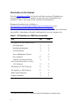
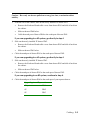
Preface
Intended Audience
This manual is for service providers of HP AlphaServer ES80s who are upgrading an ES80
system.
Document Structure
This manual uses a structured documentation design. Topics are organized into small
sections, usually consisting of two facing pages. Most topics begin with an abstract that
provides an overview of the section, followed by an illustration or example. The facing
page contains descriptions, procedures, and syntax definitions.
This manual has 4 chapters.
•
Chapter 1, Overview, introduces you to the ES80 system, its upgrade kits and
contents, and the basic steps of the upgrade procedure.
•
Chapter 2, Install and cable the drawers, guides you through removing the side
panel, installing cagenuts, brackets, and the 2P drawers for all models.. It details
placement and order of IP (interprocessor), Ethernet, power cables and ground wires for
connecting the new installed CP drawer(s) to the initial system.
•
Chapter 3, Configure and Troubleshoot, completes our installation. We assign IP
addresses to the newly installed components, and complete with a software check that
all newly installed components are seen and operating appropriately.
•
Chapter 4, Verifying with Q-Vet, gives you the Q-Vet installing, running, removing
procedures to verify the system upgrade.
ix
Information on the Internet
Visit the AlphaServer Web site for pdf and html versions of AlphaServer
documentation. This site is updated as new revisions and manuals are
produced. Table 1 lists some of the available documentation.
Firmware downloads are available at
ftp://ftp.digital.com/pub/Digital/Alpha/firmware/index.html or at
http://ftp.digital.com/pub/Digital/Alpha/firmware/index.html.
You can reach this from the external hp homepage. One URL may work more
successfully, depending on firewall configurations at your customer site.
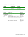
Table 1 HP AlphaServer ES80 Documentation
Title
Pdf
html
Site Preparation
Y
Y
Installation Information
Y
Y
User Information
Y
Y
Server Management Tutorial
--
Y
Service Manual
Y1
Y1
Y
Y
Y
Y
HP AlphaServer ES47 Trade-up
1
Y
Y1
HP AlphaServer ES80 Upgrade
Y1
Y1
SRM Console Reference
Y
Y
Technical Summary
Y
Y
HP AlphaServer ES47/ES80/GS1280
AlphaServer Management Station
Software Installation and User’s Guide
CLI Reference
1
x
Available for HP field service engineers and self-maintenance customers only.
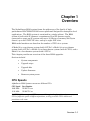
Chapter 1
Overview
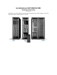
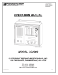
The AlphaServer ES80 system forms the mid-range of the family of highperformance ES47/ES80/GS1280 server platforms designed for enterprise-level
applications. The ES80 system is contained in a single cabinet. The ES80
system is built with 2P drawers; a maximum of four 2P drawers can be
connected to create an 8P system with up to 32 Gbytes of memory (64 Gbytes
future), up to 64 PCI/PCI-X slots, and up to eight AGP slots.
ES80 model numbers are based on the number of CPUs in a system.
A Model 2 is a one-drawer system (with 2 CPUs); a Model 4 is a two-drawer
system (with 4 CPUs), a Model 6 is a three-drawer system (with 6 CPUs), and a
Model 8 is a four-drawer system (with 8 CPUs).
This chapter provides an overview of the three ES80 upgrades.
Sections include:
•
System components
•
Upgrade steps
•
Upgrade kits
•
Update firmware
•
Remove system power
CPU Speeds
AlphaServer ES80 Systems can use two different CPUs:
CPU Speed Part Number
1000 MHz 3X-KN73A-xx
1150 MHz 3X-KN73C-xx
CAUTION: Only one type of CPU may run within a given hard partition. A system may run
CPUs of different speeds in different partitions, as long as all the CPUs within each
partition are the same.
Overview 1-1
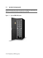
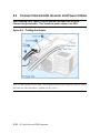
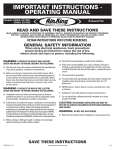
1.1
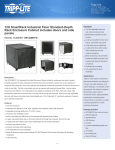
System Components
A typical ES80 system may contain from one to four 2P drawers, AC input box(es, and
a NAT box, and optional I/O drawers, storage shelves, and KVM.
Figure 1-1 Typical ES80 M8 System
1-2 HP AlphaServer ES80 Upgrades
1.2
Upgrade Steps
Here are the basic steps for installing these upgrades.
Table 1-1 Upgrade Steps
Step
To do
Resource
1
Check firmware levels; update to latest versions.
Backup important data.
Section 1.4
2
Open your upgrade kit(s) and check contents
Tables 1-2. 1-3. & 1-4
3
Shut down applications and operating system
partition(s) in an orderly fashion.
Application and
operating system guides
4
Remove power from the cabinet (unplug the
system from its outlet). Wait 5 minutes so that any
residual power is grounded.
Section 1.5
5
Remove the side panel.
Chapter 2
6
Install brackets and 2P drawer(s).
Chapter 2
7
Cable the drawers, install bezels
Chapter 3
8
Power-up systems, create new hardware addresses,
verify the installation, troubleshoot if necessary.
Chapter 3
9
Run Q-Vet.
Chapter 4
Overview 1-3
1.3
Upgrade Kits
You may install one to three of the upgrade kits,
bringing an ES80 system up to a maximum of 8 processors.
Table 1-2 ES80 Upgrade Kits by Model
Model upgrade
Processor upgrade
Upgrade Kit P/N
Model 2 to Model 4
From 2 to 4 processors
3X-BA60B-AB
Model 4 to Model 6
From 4 to 6 processors
3X-BA60B-AC
Model 6 to Model 8
From 6 to 8 processors
3X-BA60B-AD
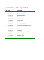
Table 1-3 ES80 Upgrade Kit Contents
(3X-BA60B -AB, -AC, or -AD)
No.
Part number
Description
1
3X-BA60B-AA
2P system building block drawer with 2 power
cords
2
17-05036-01
IP Cable assembly, COAX, 55 Ohm, (2)VHDM
1
74-61991-03
Bezel, CD, with opening, with logo
1
CK-BA60A-AA
ES80 rack kit (content details in Table 1-4)
(brackets, cagenuts, screws, Ethernet cable)
NOTE that when ordering your ES80 Upgrade, you will be prompted to order CPU and
Memory separately. The CPU and memory are installed into your 2P drawer at the factory.
Your 2P drawer for your installation arrives with your CPU and memory factory-installed
and tested. For more information, see the Quick Specs or the ES47/ES80/GS1280 Memory
Upgrade card.
1-4 HP AlphaServer ES80 Upgrades
Table 1-4 ES80 Rack Kit Contents (3X-BA60B-AA)
Amt
P/N
Description
2
17-00442-03
Power cord, 2.5M long
1
17-04991-03
Ground wire, 8AWG, #10
1
17-05097-04
Ethernet cable assembly
2
74-62102-01
Plate stop bracket
1
74-62195-01
Right slide bracket
1
74-62196-01
Left slide bracket
2
74-62199-01
Clip, front, mtg
6
90-09984-18
Screws, M5 X 0.8 X 12mm long
16
90-09984-41
Screws, Phillips pan head, SEMS, 18mm
20
90-11476-01
Nut Cage
2
70-41070-01
Cable retainer
1
90-07651-00
Locking washer
1
128557-001
Screw, self-tapping, 5.5mmx12mm
10
90-07031-00
Ties for bundling cables
1
70-41166-01
Wire handle for PCI
1
90-09984-19
Screw M4 X 0.7 X 8mm long
.
Overview 1-5
1.4
Update Firmware
You must update your system to the latest firmware levels before you power down.
Firmware downloads are available online through an ftp site and also a web address. Two
sites are available, to address any firewall challenges.
Download the latest firmware from one of these two sites:
ftp://ftp.digital.com/pub/Digital/Alpha/firmware/index.html
http://ftp.digital.com/pub/Digital/Alpha/firmware/index.html
If you are adding at least one additional 2P drawer (upgrading from a Model 2
to Model 4, for example), then you MUST upgrade your firmware before you
power down your system and begin the hardware upgrades. You cannot
successfully upgrade the hardware without updating the firmware on your
original system.
Please save all console environmental variables before power down
(use show* or show mbm commands).
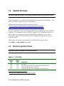
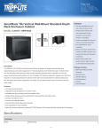
1.5
Remove System Power
Perform an orderly shutdown of the operating sytem.
Table 1-5 OCP LEDs
•
•
Amber
LED•
Green
LED•
Off
On
Off
On
Off
Off
On
On
Indication
No Vaux
Vaux on, bulk power off, attention error inside the box
Vaux on, bulk power on, no errors
Vaux on, bulk power on, attention error inside the box
The top LED is amber and the bottom LED is green.
1-6 HP AlphaServer ES80 Upgrades
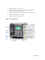
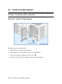
1.
Upgrade your firmware (see Section 1.4)
2.
Perform your regular system maintenance. Back up all important data,
systematically shut down your applications.
3.
Turn off power to the cabinet at the OCP, turning the 3-position switch to 0.
4.
Wait for the orderly shutdown to complete.
5.
Unplug the cabinet from its power source.
Figure 1-2 Turn Off Power
Overview 1-7
1-8 HP AlphaServer ES80 Upgrades
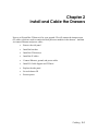
Chapter 2
Install and Cable the Drawers
Next we will install the 2P drawer(s) for your upgrade. We will connect the interprocessor
(IP) cables, which are used to connect the dual processor modules in the drawers. And then
we connect Ethernet and power cables.
•
Remove the side panel
•
Install the brackets
•
Install the 2P drawer(s)
•
Install the IP cables
•
Connect Ethernet, ground, and power cables
•
Install I/O Cable Support and 2P Bezel
•
Replace the side panel
•
Set each drawer ID
•
Restore power
Cabling
2-1
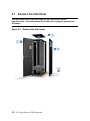
2.1
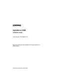
Remove the Side Panel
You must remove the right side panel (as you look at the cabinet
from the front). You need access to the side rails to properly ground each
2P drawer.
Figure 2–1 Remove the Side Panel
2-2
HP AlphaServer ES80 Upgrade
1.
Open the front door. n
2.
Pry the top panel off and lift it up.o Set it aside.
3. For the 34U and 41U cabinets, remove the screw at the bottom of the panel (front and
rear). p
For the 42U cabinets, use the door lock to unlock the side panel at the bottom.
4.
Starting at the bottom, pry the side panel away from the cabinet
5.
Lift the side panel out and up, and remove it. q
Cabling
2-3
2.2
Install the Brackets
Install the brackets that will hold the new 2P drawer.
Figure 2–2 Installing the Brackets
2-4
HP AlphaServer ES80 Upgrade
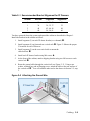
Table 2–1 Recommended Bracket Alignment for 2P Drawers
Drawer
Bracket
Cagenuts
Alignment
0
1
2
3
24
36
48
60
18, 20, 25
30, 32, 37
42, 44, 49
54, 56, 61
20
32
48
60
You have powered-down the system and opened the cabinet as described in Chapter 1.
Install the brackets in the cabinet as follows.
1.
Install cagenuts (5) on each 2P drawer bracket (or c-channel) X.
2.
Install cagenuts (8) on front and rear vertical rails Y. Figure 2–2shows the proper
U locations for each 2P drawer.
3.
Install cagenuts (2) on the rear vertical rails to mount the
cable brackets Z.
4.
Install each 2P drawer bracket using M6 screws [.
5.
At the front of the cabinet, attach a shipping bracket using two M6 screws to each
vertical rail \.
6.
Route the ground cable through the vertical rail (see Figure 2–3). Using a star
washer, terminal lug, and self-tapping screw, attach the cable to the rear surface of
the vertical rail ]. You will attach the other end to the drawer in Section 2.5, step
2.
Figure 2–3 Attaching the Ground Wire
Cabling
2-5
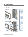
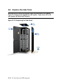
2.3
Install the 2P Drawer(s)
Slide each 2P drawer into the cabinet, using at least two people or lift
equipment.
Figure 2–4 Installing the 2P Drawer
2-6
HP AlphaServer ES80 Upgrade
CAUTION:
At least two people are required to lift and install the 2P drawer in the
cabinet. When installing drawers towards the top of the cabinet, use lift
equipment.
The approximate weight of a 2P drawer is 100 pounds.
1.
At the rear of the cabinet, lift and rest the front of the 2P drawer onto the brackets
and carefully slide it to the front of the cabinet.
2.
At the front of the cabinet, install the safety stop bracket directly into the installed
drawer front X. Using two M4 screws, tighten the safety stop bracket into the two
holes on each side of the drawer.
Cabling
2-7
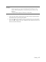
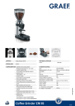
2.4
Install the IP Cables
Always cable the north port of an upper 2P drawer to the south port of the 2P
drawer immediately below. And cable the north port of the bottom 2P drawer
to the south port of the uppermost drawer.
Figure 2–5 Installing the IP Cables
2-8
HP AlphaServer ES80 Upgrade
Caution: Have only one drawer pulled out at any given time, to maintain cabinet
stability.
1.
From the rear of the cabinet, slide out the newly installed 2P drawer ID#1.
•
Remove the North and South cable covers from drawer ID#1 and slide it back into
the cabinet.
•
Slide out drawer ID#0 below.
•
Cable the north port of drawer ID#0 to the south port of drawer ID#1.
If you are upgrading to a 4P system, go directly to step 4.
2.
•
Slide out the newly installed 2P drawer ID#2.
•
Remove the North and South cable covers from drawer ID#2 and slide it back into
the cabinet.
•
Slide out drawer ID#1 below.
Cable the north port of drawer ID#1 to the south port of drawer ID#2.
If you are upgrading to a 6P system, go directly to step 4.
3.
•
Slide out the newly installed 2P drawer ID#3.
•
Remove the North and South cable covers from drawer ID#3 and slide it back into
the cabinet.
•
Slide out drawer ID#2 below.
Cable the north port of drawer ID#2 to the south port of drawer ID#3.
If you are upgrading to an 8P system, continue to step 4.
4.
Cable the north port of drawer ID#0 to the south port of your topmost drawer.
Upgrading to
Topmost drawer
4P system
ID#1
6P
ID#2
8P
ID#3
Cabling
2-9
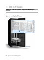
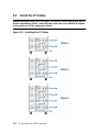
2.5
Connect Internal LAN, Ground, and Power Cables
After installing the IP cables, plug the Internal LAN cable into the HUB.
Connect the ground cable. Then install the power cables to the PDU.
Figure 2–6 Cabling the Drawer
Note: Create a proper service loop. Allow enough Internal LAN and power cable to enable
full extension when the drawer is pulled out, for service.
2-10
HP AlphaServer ES80 Upgrade
1.
Plug the internal LAN cable into drawer ID#1 X and route the cable up the right
vertical rail to the HUB. Connect the cable to the HUB.
2.
Secure the ground cable Y.
For earlier models, secure the ground cable at Z.
In Section 2.2, you threaded the other end of the ground cable up through the hole of the
left rear rail post, around the rail and secured on the other side of the rail. See Figure 2–
3 for details.
3.
Install the two power cords into the drawerZ and plug them into the cabinet’s power
distribution unit (PDU).
If the cabinet has a second PDU installed for power redundancy, then plug each cord
into separate PDUs, to configure power redundancy to this newly installed drawer.
4.
Use a tie wrap to secure the power and internal LAN cables to the drawer.
5.
Slide the drawer in.
6.
Install the third screw to secure shipping brackets to drawer [.
7.
Install the drawer-stop brackets (X in Figure 2–7 below).
Figure 2–7 Installing Drawer-stop Brackets
Cabling
2-11
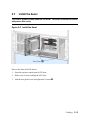
2.6
Install I/O Cable Support
Over the handle on the 2P drawer, install an extension bracket to support the
I/O cables. Tie wrap the cables to the bracket.
Figure 2–8 Install I/O Cable Support
Working from the rear of the cabinet:
1.
Find the black I/O cable extension bracket.
2.
Slip the bracket over the handle on the rear of each 2P drawer.
3.
Secure the bracket by tightening it with 2 screws. X
4.
Gather the I/O cables and tie wrap them onto the extension bracket.
2-12
HP AlphaServer ES80 Upgrade
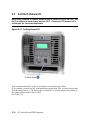
2.7
Install the Bezel
The new 2P drawer comes without a CD-ROM. The bezel is installed to shield
and protect this cavity.
Figure 2–9 Install the Bezel
Move to the front of the 2P drawer.
1.
Open the operator control panel (OCP) door.
2.
Remove the 2 screws holding the OCP door.
3.
Add the new plastic bezel and tighten the 2 screwsX.
Cabling
2-13
2.8
Replace the Side Panel
Working from the side of the system, return the side panel to the cabinet.
Figure 2–10 shows a full upgrade to an 8P system. If you have a 4P or 6P,
your system will have fewer drawers.
Figure 2–10 Replacing the Side Panel
2-14
HP AlphaServer ES80 Upgrade
1.
Hook the top of the side panel onto the cabinet. Working top down, press the side panel
onto the cabinet frame. Push the bottom in tightly.
2.
Insert and tighten the screws at the bottom of the panel (front and rear). For 42U
cabinets, lock the side panels to the frame.
3.
Press the top panel back onto the cabinet frame.
4.
Close the cabinet doors.
Cabling
2-15
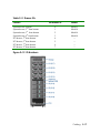
2.9
Set Each Drawer ID
Each newly installed 2P drawer needs to have a unique ID set on its OCP. Set
the ID numbers for each drawer on their OCP. Check your PCI drawer’s IDs,
so that you do not create duplicates.
Figure 2–11 Setting Drawer ID
Each component must have its ID set according to its position in the cabinet.
If, for example, you have no PCI in the position associated with ID-6, you do not assign that
ID to the drawer above it. The drawer above retains ID-7 to indicate its physical position in
the cabinet, and the drawer below is ID-5
(See Table 2–2).
2-16
HP AlphaServer ES80 Upgrade
Table 2–2 Drawer IDs
Position
System drawer, bottom
System drawer, 2nd from bottom
System drawer, 3rd from bottom
System drawer, 4th from bottom
PCI drawer, 5th from bottom
PCI drawer, 6th from bottom
PCI drawer, 7th from bottom
PCI drawer, 8th from bottom
Set drawer ID
Model
0
1
2
3
4
5
6
7
Model 2
Model 4
Model 6
Model 8
-----
Figure 2–12 ID Numbers
Cabling
2-17
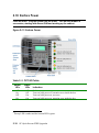
2.10 Restore Power
Close all doors. Plug the system into the outlet. Turn on each drawer in
succession, starting with drawer ID#0 and working up the cabinet.
Figure 2–13 Restore Power
Table 2–3 OCP LED Table
•
Amber
LED•
Green
LED•
Off
On
Off
On
Off
Off
On
On
Indication
No Vaux
Vaux on, bulk power off, attention error inside the box
Vaux on, bulk power on, no errors
Vaux on, bulk power on, attention error inside the box
The top LED is amber and the bottom LED is green.
2-18
HP AlphaServer ES80 Upgrade
Chapter 3
Configure and Troubleshoot
This chapter covers power-up following the hardware upgrade, and configuration of the newly
installed elements into the system using the firmware. Some troubleshooting is also included.
Examples show sample console displays for a 4P system. Changes for the 6P and 8P systems
are noted in the explanations. Two conventions are used:
1.
Sections of console output that are not relevant to verifying this upgrade have been
deleted. They are represented in the example text as:
<< ------------ lines deleted ------------- >>
Relevant sections are highlighted. Your User Information CD has complete powerup information.
2.
Commands that you input are shown in boldface type, and underlined. For example:
show cable
Sections include:
•
Notify server management of new member(s)
•
Set membership takes effect
•
Reset micros
•
Run show cable
•
Connect to partition
•
Troubleshooting during console power-up
•
Troubleshooting power during power-up
Configure and Troubleshoot
3-1
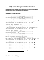
3.1
Notify Server Management of New Members
Restore power to the system. Server Management will find the new hardware,
but you need to specify their inclusion into the system.
Example 3–1 Power-Up Display
MBM> 00 01 02 03 04 05 06 07 08 09 Attaching interface lo0...done
<< ------------ lines deleted ------------- >>
ES80 Server Management Failsafe Loader V2.0-2 Starting up
<< ------------ lines deleted ------------- >>
ES80 Server Management V2.0-16 Starting up
<< ------------ lines deleted ------------- >>
.~GRP-W-(grp_Probe) MBM/PBM cab:00 drw:1 is not in the member list.
~GRP-W-(grp_Probe) Use Set Membership -add -ca 0 -dr 1 MBM Y
X
interrupt: GROUP IS FORMING
Z
...~GRP-W-(grp_Probe) MBM/PBM cab:00 drw:1 is not in the member list.
~GRP-W-(grp_Probe) Use Set Membership -add -ca 0 -dr 1 MBM
..~GRP-W-(grp_Probe) MBM/PBM cab:00 drw:1 is not in the member list.
~GRP-W-(grp_Probe) Use Set Membership -add -ca 0 -dr 1 MBM
interrupt: GROUP IS STABLE
[
<< ------------ lines deleted ------------- >>
Configuring for 2 CPUs
\
<< ------------ lines deleted ------------- >>
Running test 43, Software Alerts ... on 1 EV7s
Running test 46, Other Local Interrupt Bits ... on 2 EV7s
<< ------------ lines deleted ------------- >>
MBM Init finished at: WED APR 16 09:41:27 2003
<< ------------ lines deleted ------------- >>
MBM> ~GRP-W-(grp_Probe) MBM/PBM cab:00 drw:1 is not in the member list.
~GRP-W-(grp_Probe) Use Set Membership -add -ca 0 -dr 1 MBM ]
~GRP-W-(grp_Probe) MBM/PBM cab:00 drw:1 is not in the member list.
~GRP-W-(grp_Probe) Use Set Membership -add -ca 0 -dr 1 MBM ]
~GRP-W-(grp_Probe) MBM/PBM cab:00 drw:1 is not in the member list.
~GRP-W-(grp_Probe) Use Set Membership -add -ca 0 -dr 1 MBM ]
~GRP-W-(grp_Probe) MBM/PBM cab:00 drw:1 is not in the member list.
~GRP-W-(grp_Probe) Use Set Membership -add -ca 0 -dr 1 MBM ]
MBM> Set Membership -add -ca 0 -dr 1 MBM
3-2
HP AlphaServer ES80 Upgrades
^
Restore power to the system. You will receive a series of error messages. This is to be
expected, since the console is identifying components not yet configured into the system
network.
1.
After you return power, the system will begin its software power-up. The Server
Management will discover any newly added drawers and report them to you. X
2.
Server management tells you what command to run to include this newly discovered
drawer. Y
3.
The system will continue to power up. All during its power-up sequence it will continue
to broadcast the information shown at X and Y until you provide manual intervention to
include it in the group.
4.
In this 4P example, server management has succeeded in forming a stable group with the
included components. [ But you can see at \ that the system is only including one 2P
drawer, not your second 2P drawer, ID#1.
5.
At ], you can see that the system is still broadcasting the hardware issue and your
intervention instructions.
6.
Enter the command set membership –add –ca 0 –dr 1 MBM. ^
If you have added 2 or three 2P drawers, server management will be broadcasting the
commands you need to enter to include these additional drawers as well.
Table 3–1 Set Membership Commands
Upgrading to
Dwr ID
4P
6P
8P
1
2
3
Command
set membership –add –ca 0 –dr 1
set membership –add –ca 0 –dr 2
set membership –add –ca 0 –dr 3
Configure and Troubleshoot
3-3
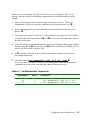
3.2
Set Membership Takes Effect
After you issue the set membership command, server management console
will process your request.
Example 3–2 Run Set Membership
MBM> Set Membership -add -ca 0 -dr 1 MBM
~GRP-W-(grp_Probe) MBM/PBM cab:00 drw:1. X
~GRP-W-(grp_Probe) Use Set Membership -add -ca 0 -dr 1 MBM
MBM> The Create task has been posted
Y
Z
After semTake
SendNewGroup - newid GROUPID: origadr:100000a incarnation:2 [
m->cnt = 2
[100000a]SendNewGroup - to node:ffffff0a creatorid:100000a
grp_Monitor_task - Message Received 101
[0100000a] NEWGROUP - from 100010a
newid GROUPID: origadr:100010a incarnation:2
NewP SETOFMICROS: cnt:2 {100000a 100010a }
[0100000a] SendAccept - to 0100010a
SendAccept newid GROUPID: origadr:100010a incarnation:2 \
SendAccept prevGID GROUPID: origadr:100000a incarnation:1
SendAccept - newid GROUPID: origadr:100010a incarnation:2
SendAccept - MicroSet SETOFMICROS: cnt:2 {100000a 100010a }
m->cnt = 2
grp_Monitor_task - Message Received 101
[0100000a] NEWGROUP - from 100010a
newid GROUPID: origadr:100010a incarnation:2
NewP SETOFMICROS: cnt:2 {100000a 100010a }
grp_Monitor_task - Message Received 104
[0100000a] JOIN - from 100010a
newid GROUPID: origadr:100010a incarnation:2
Predecessor GROUPID: origadr:[100000a2003/04/16 incarnation:
09:42:158
]
memb
SETOFMIC~REC-W-(trecTask) SeROS: cnt:rver manage2ment group is trans
{itioninga
100010a }
m->cnt = 2
Join - Micro:0100000a
g GROUPID: origadr:100010a incarnation:2
m SETOFMICROS: cnt:2 {100000a 100010a }
Predecessor GROUPID: origadr:100000a incarnation:1
interrupt: GROUP IS FORMING
]
grp_Create_task - Message Received 1f5
Missing Accept timer expired
3-4
HP AlphaServer ES80 Upgrades
Waiting for newGroupCreation to be posted
interrupt: GROUP IS STABLE
^
[2003/04/16 09:43:13]
~REC-W-(trecTask) Server management group is stable.
_
1.
Server management’s group probe is finding drawer 1 X.
2.
Since creation of the new membership incarnation is in process but not yet complete,
until the new group ID is formed, you may receive part of the broadcast message. You do
not need to re-issue the command. Y
3.
When the create task has been posted, the broadcast messages cease. Z
4.
Here the system is showing you it is creating a second incarnation of the group ID. [
5. And the system goes through its protocol of accepting this new information\.
6. The group is being formed ].
7.
The group becomes stable ^ and finally is declared stable _.
Configure and Troubleshoot
3-5
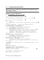
3.3
Reset Micros
Next you need to reset the Server Management micros.
Example 3–3 Run Reset Micros
MBM> reset -m(icros) -a(ll)
X
Resetting all micros....
MBM> 06 07 08 09 Attaching interface lo0...done
<< ------------ lines deleted ------------- >>
ES80 Server Management V2.0-16 Starting up
<< ------------ lines deleted ------------- >>
Running POST ...
<< ------------ lines deleted ------------- >>
Join - Micro:0100000a
g GROUPID: origadr:100000a incarnation:1 Y
m SETOFMICROS: cnt:1 {100000a }
Predecessor GROUPID: origadr:0 incarnation:0 Z
Waiting for newGroupCreation to be posted [
Forming groupppp0: ppp 2.1.2 started by 10.0.0.1
<< ------------ lines deleted ------------- >>
[0100000a] NEWGROUP - from 100010a
newid GROUPID: origadr:100010a incarnation:2
NewP SETOFMICROS: cnt:2 {100000a 100010a } \
[0100000a] SendAccept - to 0100010a
SendAccept newid GROUPID: origadr:100010a incarnation:2 ]
SendAccept prevGID GROUPID: origadr:100000a incarnation:1
SendAccept - newid GROUPID: origadr:100010a incarnation:2
SendAccept - MicroSet SETOFMICROS: cnt:2 {100000a 100010a }
m->cnt = 2
grp_Monitor_task - Message Received 104
[0100000a] JOIN - from 100010a
newid GROUPID: origadr:100010a incarnation:2
Predecessor GROUPID: origadr:0 incarnation:0
memb SETOFMICROS: cnt:2 {100000a 100010a }
m->cnt = 2
Join - Micro:0100000a
g GROUPID: origadr:100010a incarnation:2
m SETOFMICROS: cnt:2 {100000a 100010a }
Predecessor GROUPID: origadr:0 incarnation:0
...interrupt: GROUP IS FORMING ^
.....interrupt: GROUP IS STABLE _
3-6
HP AlphaServer ES80 Upgrades
1. At the MBM prompt, enter reset -m -a or reset -micros -all
X
2. The system posts its current version of the Group IDY and compares its previous Group
ID Z, and waits to accept the new information. [
3. New group information is found and incorporated. \
4. System goes through its protocol to confirm the new group incarnation. ]
5. Group is forming ^ and becomes stable. _
Configure and Troubleshoot
3-7
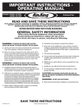
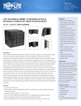
3.4
Run Show Cable
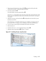
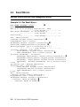
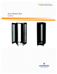
To check your IP cable connection, run show cable.
Example 3–4 Run Show Cable
MBM> show cable X
IP Cabling: Each System Building Block is represented by SBB(Cabinet,
Drawer)
Each pair of matching symbols indicates wrap-around
('X' - wrong connection, 'x' - missing connection, '?' - unknown
connection)
A0
Y
| x
-x-SBB(0,0)-x| x
|
|
|
| x
-x-SBB(0,1)-x| x
A0
Y
Z
[
IO cabling between IORs of the PCI drawer and CPU IOPs
PCI drawer
Cab Drw IOR
0
0
0
0
1\ 0
Cab
------0
------0
SBB
Drw IOP
0
0
1\ 0
MBM> p on
]
FPGA version: V3.0-0402
Read 130012 bytes
Selecting FPGA 0
Configuring for 4 CPUs
0
1
2
3
4
5
]
6
7
8
.w.....
.P........
.|.......
.|.........
]1 .P.........
]0
3-8
HP AlphaServer ES80 Upgrades
9
A
B
C
D
E
F
.|........
.|........
]2 .P........
.|........
.|........
]3 .P........
.w........
<< ------------ lines deleted ------------- >>
Running test 10, Initialize RAMBUS ... on 4 EV7s
Running test 11, Initialize Memory ... on 4 EV7s
<< ------------ lines deleted ------------- >>
Running test 43, Software Alerts ... on 1 EV7s
Running test 46, Other Local Interrupt Bits ... on 4 EV7s
<< ------------ lines deleted ------------- >>
MBM>
To check your cable connection:
1.
Enter the command show cableX
2.
The system prints out a cabling diagram. Y indicates where your south port from drawer
ID0 connects to your north port of the top drawer, in this case, drawer ID1. Detailed
diagram of the cables shown in Figure 3-4.
3.
Drawer ID0 in cabinet 0 (0,0) Z is cabled to drawer ID1 in cabinet 0 (0,1) [.
4.
The table at \ shows how the PCI I/O is connected to the CPUs:
The first line reports that the IO port of CPU0 in drawer 0 is connected to the IO7
chip in drawer 0. The second line reports that the IO port of CPU0 in drawer 1 is
connected to the IO7 chip in drawer 1.
5.
Enter the command p on ] to power on.
6.
Confirm that all of your CPUs are configured—in this example, 4. ] Each CPU is
checked and reported.
Configure and Troubleshoot
3-9
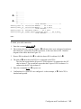
3.5
Connect to Partition
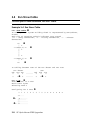
Next, connect all components to your partition(s).
Example 3–5 Run Connect
MBM>
MBM> conn(ect)
X
Connecting to partition. Use the sequence ^[^[MBM to return.
starting console on CPU 0 Y
<< ------------ lines deleted ------------- >>
Get Partition DB
hpcount = 1, spcount = 2, ev7_count = 4, Z io7_count = 2
hard_partition = 0
<< ------------ lines deleted ------------- >>
probe I/O subsystem
< ------------ lines deleted ------------- >>
starting drivers
initializing keyboard
Starting secondary CPU 1 at address 400030000 [
Starting secondary CPU 2 at address 800030000
Starting secondary CPU 3 at address c00030000
initializing GCT/FRU..... at 54c000
Initializing dqa dqb pka pkb pkc pkd pke pkf ega egb egc
AlphaServer Console V6.4-12, built on Mar 6 2003 at 14:32:06
P00>>> \
1. Enter the command conn or connect X
2. Connects to partition using your primary CPU. Y
3. Check your CPU count here. Z
4. Secondary CPUs are started up. Check that all report in. [
5. Prompt appears. Connection complete. \
3-10
HP AlphaServer ES80 Upgrades
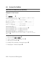
3.6
Troubleshooting During Console Power-up
If your server management keeps looping on trying to form the group, then you
need to check your NAT box carrier lights for port connections. Next check all
drawers within the cabinet (I/O and 2P drawers) to be certain they have unique
identifiers.
Issuing the Set Membership command should stop the broadcast message and enable server
management to create a new group ID. If your system keeps looping, your drawers may have
faulty connections to the system NAT box. Each Ethernet connection should show two active
LEDs.
If looping persists, check the ID numbers on the OCP of each drawer. Every drawer within
any cabinet must have a unique ID. Your 2P drawers should have Ids 0, 1, 2, and 3,
respectively, working from bottom to top.
Configure and Troubleshoot
3-11
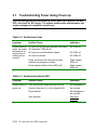
3.7
Troubleshooting Power during Power-up
If you are having difficulty with power-up, check your Vaux, internal LAN and
OCP, and check for 48V issues. The system needs certain minimal power and
system management capabilities to power-up.
Table 3–2 Troubleshoot Vaux
Symptom
Possible Cause
Indicators
System does not
power up, and/or
the fans are off,
and/or there is
nothing on the
console.
AC input box not plugged in/power cord faulty
(AC input box LEDs not lit)
AC LEDs off
AC input box circuit breakers tripped
AC LEDs off
AC input box broken
AC LEDs off
Power cords from AC input box to power
supplies not plugged in or faulty
Power supply
LEDs off
Power supplies broken (Vaux LEDs off)
Power supply
LEDs off
Table 3–3 Troubleshoot Internal LAN
Symptom
Possible Cause
System does not Poor connections along the path from the
console, wherever it is, to the internal LAN.
power up.
3-12
Indicators
No messages on
the console
Router broken
No messages on
the console
Vaux problem
See Vaux
problems
HP AlphaServer ES80 Upgrades
Table 3–4 Troubleshoot with the OCP
Symptom
Possible Cause
Indicators
System does not power up. 2P drawer OCP
48V problem
OCP LEDs off
Table 3–5 Troubleshoot 48V Issues
Symptom
Possible Cause
Indicators
System or part of Any Vaux problem will cause 48V problems
the system does
Any LAN problem
not power up
and/or the fans
Any OCP problem
are off
Signal from the MBM to the power distribution
panel on the subrack not good (cables or cable
connections)
See the Vaux,
LAN and OCP
sections of your
Service CD
Power supply
LEDs off
MBM failure
Power supply
LEDs off
More than one power supply broken
Power supply
LEDs off
Configure and Troubleshoot
3-13
3-14
HP AlphaServer ES80 Upgrades
Chapter 4
Verifying with Q-Vet
Use Q-Vet to verify your newly traded-up system.
The following topics are covered here:
•
Q-Vet Considerations
•
Run Q-Vet
•
Installing Q-Vet
•
Running Q-Vet
•
Reviewing Q-Vet Results
•
De-Installing Q-Vet
Verify with Q-Vet 4-1
4.1
Q-Vet Considerations
Select the script to run:
the short IVP to verify device setup, or the long IVP for a cycle of testing.
A short IVP script is provided for a simple verification of device setup. To run the short
script, select the appropriate file,
.Ivp_short.scp or ivp_short.vms
from the GUI IVP menu. This script will run for 15 minutes and then terminate with a
summary log. The short script may be run as a preliminary to but not in place of the long
IVP script, which is the full IVP test.
The long IVP will run a "cycle of testing", i.e. until the slowest device has completed one
pass of all tests (typically 4 or 5 hours).
Optionally, you can increase the IVP long run time by increasing the cyclecount (3 passes
are recommended). Two of the ways to do this are described. If you wish to know more
about Q-Vet features like this, see the training course at
http://learning1.americas.cpqcorp.net/wbt/cs127a-ewb/welcome.htm.
4-2
•
After executing (loading) the IVP long script, issue the Q-Vet command set
cyclecount x, where x is the number of cycles desired.
•
If you have the GUI, simply go to the menu item Options >Cyclecount and change
the setting.
HP AlphaServer ES80 Upgrades
4.2
Run Q-Vet
CAUTION: Misuse of Q-Vet may result in loss of customer data. Customers
are not authorized to access, download, or use Q-Vet. Compaq engineers use
Q-Vet during system development; they designed Q-Vet to verify system
installation during development.
Q-Vet is a Qualification Verifier Exerciser Tool used to exercise systems under
development. Run the latest released version of Q-Vet to verify that hardware is installed
correctly and is operational. Q-Vet does not verify operating system or layered product
configurations.
The latest Q-Vet release, information, Release Notes, and documentation are located at
http://cisweb.mro.cpqcorp.net/projects/qvet/ or from the quarterly AlphaServer firmware
CD-ROM. If the system is partitioned, Q-Vet must be installed and run separately on each
partition. Since Compaq Analyze is used to view Q-Vet errors, it is useful to install it prior
to running Q-Vet.
CAUTION: Do not install the Digital System Verification Software (DECVET) on the
system; use Q-Vet instead.
Run only IVP scripts on systems that contain customer data or any other devices that must
not be overwritten. See the Q-Vet Disk Testing Policy Notice on the Q-Vet Web site for
details. All Q-Vet IVP scripts use Read Only and/or File I/O to test hard drives. Floppy and
tape drives are always write-tested and should have scratch media installed.
Non-IVP Q-Vet scripts verify disk operation for some drives with write-enabled techniques.
These are intended for engineering and manufacturing test only. Q-Vet must be de-installed
upon completion of system verification.
4.2.1
Swap or Pagefile Space
The system must have adequate swap space (on Tru64 UNIX) or pagefile space (on
OpenVMS) for proper Q-Vet operation. You can set this up either before or after Q-Vet
installation.
If during initialization Q-Vet determines that the system does not have enough
swap/pagefile space, it will display a message indicating the minimum amount needed. If
you wish to address the swap/pagefile size before running Q-Vet, see the swap/pagefile
estimates on the Q-Vet web site.
Verify with Q-Vet 4-3
4.3
Installing Q-Vet
Install and run Q-Vet from the SYSTEM account on VMS or the root account on
UNIX. Remember to install Q-Vet in each partition.
4.3.1
1.
Tru64 UNIX
Make sure that there are no old Q-Vet or DECVET kits on the system by using the
following command:
setld -i | grep VET
Note the names of any listed kits, such as OTKBASExxx etc., and remove the kits
using qvet_uninstall if possible. Otherwise use the command
setld -d
kit1_name kit2_name
kit3_name
2.
3.
Copy the kit tar file (QVET_Vxxx.tar) to your system.
Be sure that there is no directory named output. If there is, move to another
directory or remove the output directory.
rm -r output
4. Untar the kit with the command
tar xvf
QVET_Vxxx.tar
Note: The case of the file name may be different depending upon how it was stored
on the system. Also, you may need to enclose the file name in quotation marks if a
semi-colon is used.
5. Install the kit with the command
setld -l output
6. During the install, if you intend to use the GUI you must select the optional GUI
subset (QVETXOSFxxx).
7. The Q-Vet installation will size your system for devices and memory. It also runs
qvet_tune. You should answer 'y' to the questions that are asked about setting
parameters. If you do not, Q-Vet will not install and the Q-Vet kit will be deleted.
8. After the installation completes, you should delete the output directory with rm r output. You can also delete the kit tar file, QVET_Vxxx.tar.
9. You must reboot the system before starting Q-Vet.
10. On reboot you can start Q-Vet GUI via vet& or you can run non GUI (command
line) via vet -nw.
4-4
HP AlphaServer ES80 Upgrades
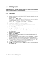
4.3.2
1.
2.
3.
4.
5.
6.
7.
OpenVMS
Delete any QVETAXPxxx.A or QVETAXPxxx.EXE file from the current directory.
Copy the self-extracting kit image file (QVETAXPxxx.EXE) to the current directory.
We recommend but do not required, that you purge the system disk before
installing Q-Vet. This will free up space that may be needed for pagefile expansion
during the AUTOGEN phase.
$purge sys$sysdevice:[*…]*.*
Extract the kit saveset with the command: $run QVETAXPxxx.EXE and
verify that the kit saveset was extracted by checking for the "Successful
decompression" message.
Use @sys$update:vmsinstal for the Q-Vet installation. The installation will
size the system for CPUs, I/O devices and memory. If you do not intend to use
the GUI, you can answer no to the question "Do you want to install Q-Vet with
the DECwindows Motif interface?" Otherwise choose all the default answers
during the Q-Vet installation. Q-Vet installation will verify, tune the system, and
reboot.
After the installation completes you should delete the QVETAXP0xx.A file and the
QVETAXPxxx.EXE file.
On reboot you can start Q-Vet GUI via $vet or the command interface via
$vet/int=char.
Verify with Q-Vet 4-5
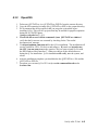
4.4
Running Q-Vet
Run Q-Vet on each partition in the system.
Review the Special Notices and the Testing Notes section of the Release Notes located at
http://chump2.mro.cpqcorp.net/qvet/ before running Q-Vet. Follow the instructions listed
for your operating system to run Q-Vet in each partition.
4.4.1
Tru64 UNIX
Graphical Interface From the Main Menu, select IVP, Load Script and select Long
IVP (the IVP tests will then load into the Q-Vet process window).
Click the Start All button to begin IVP testing.
Command-Line
Interface
> vet -nw
Q-Vet_setup> execute .Ivp.scp
Q-Vet_setup> start
Note that there is a "." in front of the script name, and that
commands are case sensitive.
4.4.2
OpenVMS
Graphical Interface
Command-Line
Interface
1.
From the Main Menu, select IVP, Load Script and select
Long IVP (the IVP tests will then load into the Q-Vet
process window).
Click the Start All button to begin IVP testing.
$ vet /int=char
Q-Vet_setup> execute ivp.vms
Q-Vet_setup> start
Note that commands are case sensitive.
4-6
HP AlphaServer ES80 Upgrades
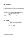
4.5
Reviewing Q-Vet Results
After running Q-Vet, check the results by reviewing the summary log.
Q-Vet will run all exercisers until the slowest device has completed one full pass.
Depending on the size of the system, this will typically take 2 to 12 hours. Q-Vet will then
terminate testing and produce a summary log. The termination message will tell you the
name and location of this file.
All exerciser processes can also be manually terminated with the Suspend and Terminate
buttons (stop and terminate commands).
After all exercisers report “Idle,” the summary log is produced containing Q-Vet specific
results and statuses.
A. If there are no Q-Vet errors, no system error events, and testing ran to specified
completion, the following message will be displayed:
Q-Vet Tests Complete: Passed
B. Otherwise, a message will indicate:
Q-Vet Tests Complete: Fail
Run Compaq Analyze to review test results. The IVP scripts do not translate events unless
they are Q-Vet detected errors. The testing times (for use with Compaq Analyze) are printed
to the Q-Vet run window and are available in the summary log.
Verify with Q-Vet 4-7
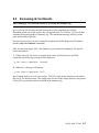
4.6
De-Installing Q-Vet
De-installation of Q-Vet differs between operating systems. You must de-install Q-Vet
from each partition in the system. Failure to do so may result in the loss of customer
data at a later date if Q-Vet is misused.
Follow the instructions listed under your operating system to de-install Q-Vet from a
partition. The qvet_uninstall programs will remove the Q-Vet supplied tools and restore
the original system tuning/configuration settings.
4.6.1
Tru64 UNIX
1. Command Q-Vet to Stop, Terminate, and Exit.
2. Execute the command qvet_uninstall, which will remove Q-Vet and restore
the system configuration/tuning file sysconfigtab.
3. Note: log files are retained in /usr/field/tool_logs
4. Reboot the system. (You must reboot, even if you decide to reinstall Q-Vet. If you
do not reboot tuning configurations may not be set properly.)
4.6.2
1.
2.
Command Q-Vet to Stop, Terminate, and Exit.
Execute the command @sys$manager:qvet_uninstall. This will remove Q-Vet
and restore system tuning (modparams.dat) and the original UAF settings.
Note: log files are retained in sys$specific:[sysmgr.tool_logs]
Reboot the system. (You must reboot even if you decide to reinstall Q-Vet. If you
do not reboot tuning configurations may not be set properly.)
3.
4.
4.6.3
•
•
•
4-8
OpenVMS
Q-Vet Resources
Release notes and kits are available from the Q-Vet web page:
http://chump2.mro.cpqcorp.net/qvet/
Training may be found at:
http://learning1.americas.cpqcorp.net/wbt/cs127a-ewb/welcome.htm
A description of the IVP may be found at:
http://chump2.mro.cpqcorp.net/qvet/IVP_description.html
HP AlphaServer ES80 Upgrades