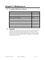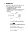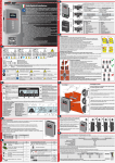
1
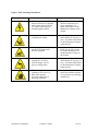
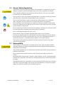
1400 Series Granulators 14 x 56 and 14 x 62 Models Models Covered: WG, 1400, MT, TG Part Number: MAN-484249 Bulletin Number: GRN2-610 Effective: August 1, 2012 Write Down Your Serial Numbers Here For Future Reference: _________________________ _________________________ _________________________ _________________________ _________________________ _________________________ We are committed to a continuing program of product improvement. Specifications, appearance, and dimensions described in this manual are subject to change without notice. DCN No. ____________ © Copyright 2013 All rights reserved. 1400 Series Granulators ii Shipping Info Unpacking and Inspection You should inspect your granulator for possible shipping damage. Thoroughly check the equipment for any damage that might have occurred in transit, such as broken or loose wiring and components, loose hardware and mounting screws, etc. In the Event of Shipping Damage According to the contract terms and conditions of the Carrier, the responsibility of the Shipper ends at the time and place of shipment. Notify the transportation company’s local agent if you discover damage. Hold the damaged goods and packing material for the examining agent’s inspection. Do not return any goods before the transportation company’s inspection and authorization. File a claim with the transportation company. Substantiate the claim by referring to the agent’s report. A certified copy of our invoice is available upon request. The original Bill of Lading is attached to our original invoice. If the shipment was prepaid, write us for a receipted transportation bill. Advise customer service regarding your wish for assistance and to obtain an RMA (return material authorization) number. If the Shipment is Not Complete Check the packing list as back-ordered items are noted on the packing list. You should have: þ Granulator þ Bill of lading þ Packing list þ Operating and Installation packet þ Electrical schematic and panel layout drawings þ Component instruction manuals Re-inspect the container and packing material to see if you missed any smaller items during unpacking. If the Shipment is Not Correct If the shipment is not what you ordered, contact the shipping department immediately. For immediate assistance, please contact the correct facility located in the technical assistance section of this manual. Have the order number and item number available. Hold the items until you receive shipping instructions. 1400 Series Granulators iii Returns Do not return any damaged or incorrect items until you receive shipping instructions from the shipping department. Credit Returns Prior to the return of any material, authorization must be given by the manufacturer. A RMA number will be assigned for the equipment to be returned. Reason for requesting the return must be given. ALL returned material purchased from the manufacturer returned is subject to 15% ($75.00 minimum) restocking charge. ALL returns are to be shipped prepaid. The invoice number and date or purchase order number and date must be supplied. No credit will be issued for material that is not within the manufacturer’s warranty period and/or in new and unused condition, suitable for resale. Warranty Returns Prior to the return of any material, authorization must be given by the manufacturer. A RMA number will be assigned for the equipment to be returned. Reason for requesting the return must be given. All returns are to be shipped prepaid. The invoice number and date or purchase order number and date must be supplied. After inspecting the material, a replacement or credit will be given at the manufacturer’s discretion. If the item is found to be defective in materials or workmanship, and it was manufactured by our company, purchased components are covered under their specific warranty terms. 1400 Series Granulators iv Table of Contents CHAPTER 1: SAFETY ................................................................ 7 1-1 1-2 1-3 1-4 How to Use This Manual ............................................................................................. 7 Safety Symbols Used in this Manual ..................................................................... 7 General Safety Regulations ...................................................................................... 10 Responsibility ............................................................................................................ 10 Warnings and Precautions ........................................................................................ 11 CHAPTER 2: FUNCTIONAL DESCRIPTION ........................... 13 2-1 2-2 2-3 2-4 Models Covered in This Manual................................................................................ 13 General Description .................................................................................................. 13 Typical Features and Components ........................................................................... 14 Hopper................................................................................................................. 14 Cutting Chamber ................................................................................................. 14 Drive System ....................................................................................................... 14 Discharge System ............................................................................................... 14 Base .................................................................................................................... 14 Safety Features ......................................................................................................... 15 Motor Starter ....................................................................................................... 15 Safety Switches ................................................................................................... 15 Safety Tags ......................................................................................................... 15 Brake Motors (Optional) ...................................................................................... 15 Sound Reduction Equipment .............................................................................. 15 CHAPTER 3: INSTALLATION.................................................. 16 3-1 3-2 3-3 3-4 3-5 3-6 Uncrating the Equipment........................................................................................... 16 Belt Tensioning ......................................................................................................... 16 Electrical Connections ............................................................................................... 17 Accessing the Cutting Chamber................................................................................ 18 Closing the Cutting Chamber .................................................................................... 18 Initial Start-up ............................................................................................................ 19 CHAPTER 4: OPERATION....................................................... 20 4-1 4-2 4-3 4-4 Start-up ..................................................................................................................... 20 Feeding the Granulator ............................................................................................. 20 Clearing a Jammed Cutting Chamber ....................................................................... 20 Shut-down ................................................................................................................. 21 CHAPTER 5: MAINTENANCE ................................................. 22 5-1 5-2 5-3 5-4 5-5 Preventative Maintenance Schedule ......................................................................... 22 Lubrication ................................................................................................................. 22 Replacing and Adjusting the Knives .......................................................................... 23 Rotor Knives ........................................................................................................ 23 Bed Knives .......................................................................................................... 24 Sharpening the Knives .............................................................................................. 24 Adjusting Belt Tension .............................................................................................. 25 1400 Series Granulators v 5-6 Rotor Bearing Replacement ...................................................................................... 27 CHAPTER 6: TROUBLESHOOTING ....................................... 28 6-1 6-2 6-3 6-4 Introduction ............................................................................................................... 28 Electrical Faults ......................................................................................................... 29 Processing Faults ...................................................................................................... 30 Mechanical Faults ..................................................................................................... 31 CHAPTER 7: APPENDIX.......................................................... 32 7-1 7-2 7-3 7-4 7-5 7-6 7-7 Recommended Torque for Screws ........................................................................... 32 Technical Specifications ............................................................................................ 33 Features .............................................................................................................. 33 Specifications ...................................................................................................... 33 Drawings ................................................................................................................... 34 Dimensions (14 x 56 model) ............................................................................... 34 Pneumatic Hopper Actuator Assembly ..................................................................... 35 Prior to Operation ................................................................................................ 35 Operation............................................................................................................. 35 Closing the Tilt Plate and Hopper ....................................................................... 36 Maintenance ........................................................................................................ 36 Pneumatic Actuator Assembly Spare Parts List .................................................. 36 Pneumatic Actuator Assembly Typical Wiring Diagram ...................................... 37 Feed Roll Assembly .................................................................................................. 38 Feed Roll Contact Pressure ................................................................................ 38 Lubrication ........................................................................................................... 38 Cleaning the Feed Roll Assembly ....................................................................... 39 Removal of Rolls ................................................................................................. 39 Adjusting the Clearance Between the Feed Roll and Stripper Bar ..................... 39 Feed Roll Assembly Spare Parts List (14 x 56 Model) ........................................ 40 Load Sensing System ............................................................................................... 41 Setting the Load Sensing System ....................................................................... 41 Technical Assistance ................................................................................................ 42 Parts and Service Department ............................................................................ 42 Sales and Contracting Department ..................................................................... 42 1400 Series Granulators vi Chapter 1: Safety 1-1 How to Use This Manual Use this manual as a guide and reference for installing, operating, and maintaining your granulator. The purpose is to assist you in applying efficient, proven techniques that enhance equipment productivity. This manual covers only light corrective maintenance. No other maintenance should be undertaken without first contacting a service engineer. The Functional Description section outlines models covered, standard features, and safety features. Additional sections within the manual provide instructions for installation, preoperational procedures, operation, preventive maintenance, and corrective maintenance. The Installation chapter includes required data for receiving, unpacking, inspecting, and setup of the granulator. We can also provide the assistance of a factory-trained technician to help train your operator(s) for a nominal charge. This section includes instructions, checks, and adjustments that should be followed before commencing with operation of the granulator. These instructions are intended to supplement standard shop procedures performed at shift, daily, and weekly intervals. The Operation chapter includes a description of electrical and mechanical controls, in addition to information for operating the granulator safely and efficiently. The Maintenance chapter is intended to serve as a source of detailed assembly and disassembly instructions for those areas of the equipment requiring service. Preventive maintenance sections are included to ensure that your granulator provides excellent, long service. The Troubleshooting chapter serves as a guide for identification of most common problems. Potential problems are listed, along with possible causes and related solutions. The Appendix contains technical specifications, drawings, schematics, parts lists, and available options. A spare parts list with part numbers specific to your machine is provided with your shipping paperwork package. Refer to this section for a listing of spare parts for purchase. Have your serial number and model number ready when ordering. Safety Symbols Used in this Manual The following safety alert symbols are used to alert you to potential personal injury hazards. Obey all safety messages that follow these symbols to avoid possible injury or death. DANGER indicates an imminently hazardous situation that, if not avoided, will result in death or serious injury. WARNING indicates a potentially hazardous situation or practice that, if not avoided, could result in death or serious injury. CAUTION indicates a potentially hazardous situation or practice that, if not avoided, may result in minor or moderate injury or in property damage. 1400 Series Granulators Chapter 1: Safety 7 of 43 Figure 1: Belt Tensioning Information Hazard Alert Symbol 1400 Series Granulators Description/Explanation Preventative Maintenance High Voltage Hazard. The electrical enclosure is supplied with 3-phase electrical power. Use caution when using or maintaining this product. Every six months inspect all electrical connections for secure attachment. For further information see the Maintenance Chapter in this manual Hands could be exposed to a crushing movement. Every month inspect the shears/blades for any type of wear. For further information see the Maintenance Chapter in this manual. When equipped with belts and sheaves, hands could become entangled. Every month inspect the belt(s) for any type of wear. For further information see the Maintenance Chapter in this manual. Hands can become entangled or cut if they enter the danger zone of gears or cutting shears. Every month inspect the shears/blades for any type of wear. For further information see the Maintenance Chapter in this manual. The unit can produce continuous noise above 85 dBA and/or produce projectiles under normal operating conditions. Always wear eye and ear protection when the machine is in operation or performing maintenance. Chapter 1: Safety 8 of 43 Mandatory Symbol Description/Explanation Read Operators Manual. This equipment must be operated and maintained by properly trained personnel. The information contained within this manual must be read and understood prior to operating this equipment. Lock Out. This equipment is operated with 3-phase electrical power. Therefore, when performing any maintenance operations we recommend following the local standards for performing a lock-out/tag-out procedure. Wear Safety Gloves. This equipment operates with sharp blades and rotors. We recommend that technicians use safety gloves while performing maintenance to protect hands from being exposed to these sharp surfaces. Wear ear and eye protection. This unit may produce loud and continuous noise and may produce projectiles. Pneumatic or hydraulic equipment. Pneumatic or hydraulic equipment must be kept at a safe pressure. Do not reach into unit. Reaching into a unit is prohibited while the unit is in operation and may cause serious injury. 1400 Series Granulators Chapter 1: Safety 9 of 43 1-2 General Safety Regulations This machine uses knives for the performance of its intended use. Consequently, it can be a dangerous machine to operate and maintain unless these safety regulations are followed. These regulations should be read, understood, and periodically reviewed by all personnel involved in any way with this machine. Never operate or remove any machine components that are secured by wrench-type fasteners unless the motor is electrically locked out and the rotor is motionless. Never operate the machine or jog the rotor unless the cutting chamber covers, discharge chute, and guards are in place and secure. Do not circumvent the safety interlocks. Prior to clearing a jam or performing any maintenance, the motor should be turned off and electrically locked out. Be sure that the rotor has come to a stop. Hands must not be inserted into the machine to clear the jam. Do not extend any part of the body into feed roll openings or discharge area unless the motors are electrically locked out and the rotor and feed rolls are motionless. Never extend fingers through holes in the screen. Be sure that the v-belts are properly aligned and that tension is at its maximum. Extreme care should be taken to see that all bolts are properly tightened at all times. During the operation of the machine, rotor knife bolts may come loose. Although fine threads are used on the rotor knife, you should inspect the tightness of the bolts frequently. This machine is designed for the granulation of plastic materials. Do not feed any other materials into the machine. 1-3 Responsibility These machines are constructed for maximum operator safety when used under standard operating conditions and when recommended instructions are followed in the maintenance and operation of the machine. All personnel engaged in the use of the machine should become familiar with its operation as described in this manual. Proper operation of the machine promotes safety for the operator and all workers in its vicinity. Becoming familiar with materials, inspection, speed limitations, screens, guard maintenance, and total user responsibility will assist you in learning potential areas in need of observation for danger. Each individual must take responsibility for observing the prescribed safety rules as outlined. All caution, warning and danger signs must be observed and obeyed. All actual or potential danger areas must be reported to your immediate supervisor. 1400 Series Granulators Chapter 1: Safety 10 of 43 1-4 Warnings and Precautions Our granulators are designed to provide safe and reliable operation when installed and operated within design specifications, following national and local safety codes. To avoid possible personal injury or equipment damage when installing, operating, or maintaining this granulator, use good judgment and follow these safe practices: þ LEARN AND OBEY your company’s safety policy regarding granulating equipment. þ MOVING OR LIFTING THE GRANULATOR: Although our equipment is built and engineered for great ruggedness in operation, care must be taken when moving the machine along the floor or lifting it. Damage may occur to sheet metal covers, electrical cabinets, or small brackets if pressure is applied to them when moving the granulator. When lifting the granulator, be certain of total machine weight and the capability of the lifting equipment. (See the Granulator Specification Sheets for machine weights and dimensions.) þ GRANULATOR LOCATION: Adequate area for routine maintenance should be provided in order to open the machine for knife, screen, or cleanout service. Proper service area clearances also should allow people who are working on the machine to be clearly visible to others, thereby reducing potential safety hazards. þ SAFE HOUSEKEEPING: The work area must be kept clean and uncluttered during periods of operation or maintenance. No hand tools or other metal objects should be left on or around the machine. Any tools or other metal objects that mistakenly fall into the hopper feed opening can cause severe damage to the internal cutting chamber, rotor and screen components. þ SAFETY GLASSES OR A FACE SHIELD MUST ALWAYS BE WORN when servicing or operating the machine. Although our machines are designed for the maximum in fly back control, caution must be used when operating near the hopper feed opening in order to guard against unexpected material fly back. þ EAR PROTECTION may be required when operating the machine during granulation of very hard or noisy materials. The Occupational Safety and Health Act of 1970 has established guidelines for Permissible Noise Exposures (OSHA 1910.95) that should be followed. þ NEVER attempt to operate the granulator unless it is fully assembled with all guards and interlocks in place and functional. þ OBSERVE all danger, warning, caution and safety labels on the equipment. þ Upon completion of any machine maintenance, be certain ALL SAFETY GUARDS AND COVERS are securely and properly fastened prior to resuming machine operation. All fasteners must be in place and properly tightened. ANY SHORTCUTS MAY RESULT IN INJURY TO PERSONNEL OR DAMAGE TO EQUIPMENT. þ NEVER wear any loose fitting clothes, neckties, or dangling items such as earrings, belts, or shoestrings. Jewelry, such as wristwatches, bracelets, or rings should NEVER be worn. Long hair must be tied back or placed in a tight fitting hairnet. NEVER lean against or rest hands or feet on the granulator when it is in operation or open for maintenance. NEVER stand on the granulator when it is in operation. 1400 Series Granulators Chapter 1: Safety 11 of 43 þ ROTATION OF MOTORS: The correct rotating direction for the granulator motor is clearly marked on the machine. Always check for proper rotation of motors. Incorrect rotation direction can cause severe damage. þ ELECTRICAL GROUNDING: All electrical equipment on the granulator must be grounded in accordance to all local codes and Article 250 of the National Electric Code. þ ALWAYS DISCONNECT AND LOCKOUT the main electrical power to the granulator before performing any service. þ SAFETY INTERLOCKS MUST NOT BE BYPASSED. The mechanical and electrical safety interlocks ensure the safety of personnel. They should never be tampered with or removed for ANY reason. They should be checked frequently by a qualified mechanic for proper operation. þ NEVER modify the machine configuration or any individual component without written notice from the factory. For further information on granulator safety, installation and operation, see the American National Standard for Plastics Machinery⎯Granulators, Pelletizers, and Dicers Used for Size Reduction of Plastics⎯Construction, Care, and Use. ANSI B151.11-1982. We have long recognized the importance of safety and have designed and manufactured our equipment with operator safety as a prime consideration. We expect you, as a user, to abide by the foregoing recommendations in order to make operator safety a reality. 1400 Series Granulators Chapter 1: Safety 12 of 43 Chapter 2: Functional Description 2-1 Models Covered in This Manual This manual provides the necessary instructions for the installation, set-up, and maintenance of our 14 x 56 and 14 x 62 granulators. 2-2 General Description This granulator is a rugged, rotary-cutting machine specifically designed to cut, chip, and granulate the toughest plastic materials with a minimum expenditure of horsepower. A massively built, low RPM, high inertia rotor with chevron knives accepts large parts with ease and assures long, trouble-free service. The bed knife block is made of heavy steel, and the cutting chamber is made of a thick steel plate with integral oversize bearing housings. The hopper is designed to tilt back, and the screen cradle to swing down for quick access into the cutting chamber. Reclamation of sprues, runners, and small parts for inclusion and application in any type of molding or extrusion equipment is designed-in capability and depending on screen size used, this machine will provide pellets or chips to meet most requirements. 1400 Series Granulators Chapter 2: Functional Description 13 of 43 2-3 Typical Features and Components Hopper The hopper is an upright enclosure bolted to the top of the cutting chamber. The hopper is designed to facilitate the feeding of material to the rotary knives and to protect the operator from material that may be thrown out. Cutting Chamber The cutting chamber is a rectangular enclosure comprise of the main frame, the bed knives, the bed knife shields, a balanced rotor, and a screen. The main frame of the cutting chamber carries the bed knives and the bed knife shields. The downstroke bed knife shield is adjustable. The screen is supported in position below the rotor and acts as a separating barrier to the granulated material, retaining the material in the cutting chamber until the particle size is such that it will pass through the screen holes. The rotor carries the rotor knives. The rotation of the rotor produces a cutting action between the rotor knives and the stationary bed knives, thus reducing the material size. Drive System The rotor is indirectly driven by the motor through v-belts. The motor shaft pulley, v-belts, and the rotor shaft pulley are shielded by safety guards or a sound enclosure. The motor is mounted on an adjustable sliding base, which is mounted at the left end of the granulator. Discharge System On models fitted with an airveying system (optional), the granulated material that has fallen through the screen is collected in a transition piece located beneath the cutting chamber. The transition piece is connected to a blower, which conveys the granulated material through ducting to the cyclone separator. The cyclone separator allows the granulated material to drop out of the air system into a container. Base The base is a floor mounted airveyor type supporting the cutting chamber on its top surface and the airveyor chute from below the top surface. This base should be fastened securely to the surface beneath it. 1400 Series Granulators Chapter 2: Functional Description 14 of 43 2-4 Safety Features Motor Starter A magnetic motor starter with control transformer must be used when safety switches are installed. Manual starters should not be used under any conditions. Safety Switches Safety switches at all access covers are wired into the starter control circuit. The machine cannot be started when these parts are open. However, for safety purposes, the machine should be disconnected from the power lines by a disconnect switch or by removing the plug from its receptacle. Check all safety switches periodically for proper operation. Safety Tags A set of metal plates are attached to the machine to warn of potential danger. Brake Motors (Optional) An integral brake stops the motor within a few seconds of actuation of the stop button, greatly reducing the time required for the rotor to stop. Sound Reduction Equipment Sound reduction equipment will bring the sound level of your machine to within the limitations of the Occupational Safety and Health Act. Material, part configuration, feed rate, and ambient noise level must be specified at the time of inquiry. 1400 Series Granulators Chapter 2: Functional Description 15 of 43 Chapter 3: Installation 3-1 Uncrating the Equipment The complete granulator, including accessory and auxiliary equipment, is skidded for shipment. Refer to the Appendix for detailed dimensional data and pertinent weights. Prepare in advance the site you have selected for installation of the granulator. Be certain that the area to be occupied by the machine is clean, level, and free of obstructions. The machine should be set on a concrete floor, and care must be taken when moving the machine across a hollow timber floor, so that the point loading of the casters does not cause damage. The site you have selected must have a floor rating to adequately support the weight of the machine. If necessary, use steel shims to level the machine. Locate the machine so that access is given to electrical components, screen, and hopper. Maintenance personnel should have unobstructed access to the units on which they will be working. To avoid squeezing people working near a machine, there should be adequate clearance maintained between machines, walls, or partitions. Hinged doors and covers should have full swing. Restrictions may force work in cramped quarters. An off-balance operator with an awkward reach into a partially obscured area is unsafe. If inspection after shipment has revealed no shipping damage, unpack the unit by removing all hold-downs, tie-downs, bolts, nuts, etc. Remove the envelope with the electrical schematics and instruction manual from the base evacuation area. You can now have the machine lifted from the skid. To lift and move the granulator safely and correctly, cover any sharp corners or edges, and use the type of equipment that has the most appropriate features and capacity. Use the designated lifting points, and do NOT lift the machine by the hopper handles or guards. Because of the size and weight of the granulator, we recommend that only qualified riggers be employed to unpack and locate the granulator. 3-2 Belt Tensioning Tension the belts at the maximum recommended force. Check the tension at least twice during the first day of operation. See Section 5-5 on page 25 for the belt tensioning procedure. 1400 Series Granulators Chapter 3: Installation 16 of 43 3-3 Electrical Connections Granulator controls (if ordered) are shipped separately for mounting at a suitable location. The safety switches are connected to a common terminal box for ease of wiring. The customer is required to provide a suitable fused supply with a disconnect switch and a cable for the incoming line to the starter. Refer to the technical specifications in the Appendix for horsepower, voltage, phase, and frequency requirements to determine the size and rating of the supply cable required. If optional controls are required, an electrical wiring diagram will be provided with the machine in addition to the basic electrical diagram. When the customer is providing either the motor or the starter, the machine must be wired in accordance with the basic electrical diagram and the starter manufacturer’s instructions. Use the following procedure to complete the electrical connections: 1. Check to be certain that the starter heater elements correspond with the motor requirements. If controls are not supplied, the limit switches supplied on the machine must be wired into the circuit at the common terminal box. 2. Check that the limit switches are closed. 3. Turn switch ON at main power supply. 4. Jog the motor by pressing the START and then the OFF button. This starts and stops the motor. 5. With the electrical power ON, check that the motor rotates in a clockwise direction at the viewing port in the belt guard. If motor rotation is correct, continue to the next step. If rotation is incorrect, complete the following procedure: a. Shut power OFF and disconnect incoming power supply. b. Reverse any two of the three power line connections to the machine. c. Re-connect the incoming power supply line and turn ON the main power switch to recheck motor drive rotation. 6. If an airveying system (optional) is fitted, press the Airveyor START button, and check the blower motor rotation. The blower motor should rotate in a counterclockwise direction. If blower motor rotation is correct, continue to step 7. If blower motor rotation is incorrect, complete the following procedure: a. Shut power OFF and disconnect incoming power supply line. b. Reverse any two of the three power line connections to the blower motor. c. Re-connect the incoming power supply line, and recheck the blower motor rotation. 7. Allow all motors to run up to speed for at least 30 seconds. 1400 Series Granulators Chapter 3: Installation 17 of 43 3-4 Accessing the Cutting Chamber You will need to access the cutting chamber before initial startup and for various maintenance procedures. Use the following procedure to access the cutting chamber: 1. Turn the main power off, remove the line fuses, and tag the machine as out of service. 2. Remove the hex head bolts along the top of the cutting chamber downstroke covers and inside covers. 3. Swing covers downward using the handle that is provided on each cover. Do not allow covers to drop freely of their own weight. 4. Remove the upstroke cover by removing the hex head bolts. 5. Lift the cover from cutting chamber. 6. Drop the screen cradle by removing the hex head bolts. 7. Pivot the hopper to the raised or open position. 3-5 Closing the Cutting Chamber After completing any maintenance or adjustments inside the cutting chamber, use the following procedure to close the cutting chamber and resume use of the granulator: 1. Replace the screen; raise the screen and cradle into its proper position and replace the bolts. 2. Swing the downstroke doors of the cutting chamber back into their closed position and replace bolts. 3. Replace the upstroke cover and bolts. 4. Lower the hopper assembly into operating position. 5. Rotate the rotor by hand from outside the machine to check that no tools, gauges, or loose parts have been left on or in the machine. 6. Replace line fuses, turn power on, and remove the out of service tag from the machine. 1400 Series Granulators Chapter 3: Installation 18 of 43 3-6 Initial Start-up This machine has been run under power and tested at the factory prior to shipment. The necessary settings and adjustments have been made so that a minimum amount of setting up or re-adjustment is required when starting up the machine in its new location. With all electrical, mechanical connections and lubrication requirements having been attended to, the following start-up steps should be carefully carried out before attempting to place any material into the infeed hopper. Use the following procedure to prepare the machine for initial start-up: Before operating the granulator, ensure that the granulator has been correctly assembled and wired. 1. Access the cutting chamber as described in Section 3-4 on page 18. 2. Thoroughly clean the rust preventative materials or grease from the inside of the cutting chamber and screen. 3. Check all rotor knives to make sure they are properly seated on the rotor and securely fastened. Although they are ground as a set, one knife will probably be .001” to .002” higher than the others. This should be marked and used when adjusting the bed knives for proper clearance. 4. Use a feeler gauge to check the clearance between the rotor and the bed knives by turning the rotor backwards. Rotating the rotor backwards gives a better feel and does not cut the gauge, should the knives be too close. Check the knives on each end only. Proper clearance is 0.005” to 0.008” for most materials; 0.014” to 0.016” for solid wall pipe with 0.187” wall thickness or greater. This clearance is slightly greater at the center of the knives. Recheck knife clearance after the first 24 to 36 hours of operation. 5. To make the adjustment on the bed knives, the bed knife bolts should be hand tightened to hold the knife firmly against the knife seat while adjusting the knife forward using push and pull screws. After the clearance is set, torque the screws according to Section 7-1 on page 32. 6. With the exposed parts of the machine thoroughly clean, and all knife clamping bolts securely fastened, close the cutting chamber as described in Section 3-5 on page 18. After initial start-up, the rotor knife retaining screws should be checked after 8 hours running to be assured that 220 Ft. Lb. of torque is maintained. Thereafter, rotor knife retaining screws should be checked weekly. The rotor must be rotated at least two rotations every 30 days to prevent brinnelling and corrosion of raceways. 1400 Series Granulators Chapter 3: Installation 19 of 43 Chapter 4: Operation 4-1 Start-up Before starting the machine, check that the rotor rotates freely by rotating it by hand from outside the machine using either the coupling or the sheave depending on the type of drive. Inspect the cutting chamber carefully to insure that nothing has fallen into it. Make sure all screws and bolts are properly secured. Check all electrical connections and motor rotations. See Chapter 3 on pages 16-19 for detailed set-up instructions. Allow all motors to run up to speed for at least 30 seconds. 4-2 Feeding the Granulator Feed the granulator through the opening in the hopper. The method of feeding the granulator depends on the physical form and nature of the material being processed. For maximum efficiency, the granulator should be fed at a rate that is consistent with its capacity; i.e., if the granulator is rated at 60 kg/hr (132 lbs./hr.), then the general feed rate is 1 kb/min. (2.2 lbs./min.). Under these operating conditions, the correct proportions of cut and uncut particles will be present in the cutting chamber. Under no circumstances should the operator attempt to reach into the hopper to dislodge any bridged or jammed material while the granulator is in operation. To clear the hopper of bridged or jammed material, the machine main power must be turned off and the machine isolated. 4-3 Clearing a Jammed Cutting Chamber Never attempt to free a jammed machine by placing hands on the rotor, rotor knives, or inside the cutting chamber. Hands must be kept clear of the rotational path of the rotor knives. Good footing on a clean floor is essential and the body should be well braced to guard against loss of balance should the jam suddenly come free. Use the following procedure to clear a jammed cutting chamber: 1. Disconnect and lock out power. 2. Be certain that the rotor is motionless. 3. Open the machine as instructed in Section 3-4 on page 18. 4. Use a pry bar to exert force on the rotor, usually in the direction opposite normal rotation. A leather mallet and a block of wood of sufficient length can be used to keep hands away from the path of the knives. 5. Use pliers to remove material from the cutting chamber, keeping in mind that the removal of material may cause rotation of the rotor and rotor knives. 6. After clearing the jam, be certain that the screen and all guards and covers are secured in place before connecting power and starting the machine. 1400 Series Granulators Chapter 4: Operation 20 of 43 4-4 Shut-down Use the following procedure to properly and safely shut down the machine: 1. Stop all feeding of material. 2. Allow the granulator to run until the cutting chamber is completely empty. 3. Press the drive motor “stop” button. This shuts off the rotor drive motor. 4. After the granulator has stopped, press the airveyor stop button (if applicable) located at the blower motor. 5. Turn the main power switch to off. 1400 Series Granulators Chapter 4: Operation 21 of 43 Chapter 5: Maintenance 5-1 5-2 Preventative Maintenance Schedule Check Frequency Knife clearance Weekly Knife retaining screws for tightness Weekly Knife exposure Weekly Shield retaining screws for tightness Weekly Screen retaining studs for tightness Weekly Lubrication of drive motor bearings Monthly Lubrication of rotor bearings Monthly Screen Wear Monthly Belt tension Monthly Hopper and cutting chamber screws are tight Monthly Lubrication When the machine is shipped, the bearings are filled with grease. The bearings should require no lubrication for a month under usual operating conditions. If the machine is operated continuously, it may be desirable to lubricate the machine every two or three weeks. This machine should be lubricated with a high temperature bearing grease. We suggest Alemite #38, Sun Oil #844, Sunoco Prestige 741EP, Sovarex #2, Shell EP Grease #1, Mobilux EP-2, or Esso Multi-purpose Grease H. 1400 Series Granulators Chapter 5: Maintenance 22 of 43 5-3 Replacing and Adjusting the Knives During use, the clearance between the rotor knives and the bed knives will increase due to wear. This is a normal condition that requires re-setting this clearance once or twice before it is necessary to remove the knives for regrinding. Check the knives weekly for wear, clearance, exposure, and screw tightness. When new knives are fitted to the machine, adjustment after eight hours of running time may be required. Before assembling a new or reground set of knives, make sure the knife seats and mounting holes are clean. Do not use grease or oil on screws or tapped holes when assembling the knives. Knives must be replaced in complete sets; otherwise it will not be possible to obtain even clearance between the rotor knives and bed knives. Before applying a wrench to any knife bolt, be certain that the rotor is blocked to prevent rotation. One such method is to use a block of wood at least 1 1/2” thick between a knife and a fixed portion of the frame. Rotor Knives We recommend that the rotor knife screws be replaced with new screws every sixth knife change to reduce the risk of screw failure due to overstretching. Screws must be replaced with the type specified in the spare parts list. Use the following procedure to replace or adjust the rotor knives: Rotor knives should be changed one seat at a time to prevent rotor from being rotated in an out-of-balance condition. 1. Access the cutting chamber as directed in Section 3-4 on page 18. 2. Loosen check nuts on bed knife adjusting screws and back off screws. 3. Remove bed knife shields. 4. Disengage bed knife pull screws. 5. Remove the bed knife bolts and bed knives. 6. Remove rotor knife bolts and knives on one seat. This should be done from the downstroke side of the cutting chamber. 7. Thoroughly clean knife seat. 8. Install new knife on seat and tighten knife bolts. See Section 7-1 on page 32 for torque recommendations. Bolt threads should not be oiled. Wipe thread with an oil-dampened cloth. 9. Repeat steps 6 through 8 for each rotor knife. 1400 Series Granulators Chapter 5: Maintenance 23 of 43 Bed Knives We recommend that the same screws and washers be re-used only when the bed knives have been repositioned or re-ground. When blunt knives are discarded and replaced with new knives, use new screws and washers. This will reduce the risk of screw failure due to their overstretching. Screws and washers must be replaced with the type specified in the Spare Parts List. Use the following procedure to replace or adjust the bed knives: 1. Access the cutting chamber as directed in Section 3-4 on page 18. 2. Loosen the check nuts on the bed knife adjusting screws and back off screws. 3. Remove the bed knife shields. 4. Disengage the bed knife pull screws. 5. Remove the bed knife bolts and bed knives. 6. Before installing and adjusting the bed knives, check all rotor knives to make sure they are properly seated on the rotor and securely fastened. 7. Place the downstroke bed knife and its shield in place and hand-tighten the knife bolts to hold them firmly to the knife seats. 8. Using the push and pull screws to set the knife clearance to 0.005” to 0.008” for most materials; 0.014” to 0.016” for solid wall pipe with 0.187” wall thickness or greater. The clearance should be measured with a feeler gauge at the ends of the knife, by rotating the rotor sheave backwards by hand. The clearance is slightly greater at the center of the knives. 9. Adjust the shield using its push and pull screws so that its front edge is within 1/16” of the bed knife edges. 10. Tighten all bolts using the recommended torque values in Section 7-1 on page 32. 11. Repeat steps 7 through 10 for the upstroke bed knives. 5-4 Sharpening the Knives Under normal operating use, the cutting edge of the knives will eventually become dulled, resulting in reduced cutting efficiency. The blunt knives may either be re-ground to restore the cutting edge, or replaced with new knives when regrinding is not possible. When sharpening, it is not harmful to allow a few small nicks to remain in the cutting edge. Grinding the cutting edge until perfectly clean can sometimes be wasteful. 1400 Series Granulators Chapter 5: Maintenance 24 of 43 5-5 Adjusting Belt Tension For continuous reliable operation of the granulator, it is important that the belt tension is correct. Correct tension reduces wear on rotor and motor bearings and keeps belt slip to a minimum. Figure 2 gives the recommended force to deflect each belt by an amount equal to the belt span divided by 64. A gauge is available through the sales department to measure the deflection and force. Use the following procedure to adjust the belt tension: 1. Turn off the granulator at the main isolator switch and remove fuses. 2. Remove the cover to gain access to the belts. 3. Turn the adjusting screw on the motor slide base to tension the belts as required (See Figure 2). 4. Re-tighten the screws, making sure the pulleys are in correct alignment. 5. Replace the covers. 1. Verify that the alignment of the pulley is correct. Utilizing a straightedge of sufficient length to span from one pulley to the other, place it along the sides of both pulleys. The entire face of each pulley should fully contact the straightedge. 2. Measure the belt SPAN with a measuring tape. Record this dimension in your note book. 3. Using the deflection tester, apply a perpendicular force at the midpoint of any one of the belts to deflect the belt 1/64th of an inch. 4. Calculate the deflection force: FORCE[Lb]= SPAN[IN] X (1/64)[Lb/IN] 5. Identify the belt type and measure the small sheave diameter. Look up the proper model belt deflection force table and find out what the force is supposed to be. 6. The motor position should be adjusted until the actual deflection force matches the force listed in the table. 1400 Series Granulators Chapter 5: Maintenance 25 of 43 7. In no case should the belts be over tensioned, as this can significantly reduce belt and/or bearing life Figure 2: Belt Tensioning Information BELT SMALL CROSS SHEAVE SECTION DIA. A B C D E DEFLECTION FORCE: LBS. STANDARD SUPER GRIPBELTS GRIPBELTS 4.25 GRIPNOTCH BELTS STEEL CABLE GRIPBELTS 3.0-‐3.6 3.5 3.8-‐4.8 4.25 5.0-‐7.0 4.75 3.4-‐4.2 4.375 5.5 8 5.5 4.4-‐5.6 6 7.125 9.125 7.25 5.8-‐8.6 7.75 8.75 10.125 8.75 7.0-‐9.4 12.25 14.375 17.875 14 9.6-‐16 15.75 18.5 20.25 17.75 12.0-‐16.0 25.5 30.25 30.5 18-‐27 33.25 39.5 39.25 20-‐32 45.25 BELT CROSS SECTION SMALL O.D. RANGE 5.5 4 5 6.25 4.75 5.5 6.875 5.25 DEFLECTION FORCE: LbS 3V 2.65-‐3.65 4.12-‐6.9 5 6.9 5V 7.1-‐10.9 11.8-‐16.0 16 20 8V 12.5-‐17.0 18.0-‐22.4 41 45 1400 Series Granulators Chapter 5: Maintenance 26 of 43 5-6 Rotor Bearing Replacement Use the following procedure to remove and replace the rotor bearings: 1. Shut off the machine and the main power disconnects. 2. Remove the flywheel guard and drive belts. 3. Disconnect the thermal sensors. 4. Loosen the flywheel sheave bushings and bolts, and remove the shaft end cap. Remove the flywheel and bushing. Loosen bolts on the bearing end cap and sheave spacer. 5. Clean grease and dirt from the bearing’s exposed surfaces and shaft surfaces. 6. Remove the bearing housing containing the bearing from the shaft using the symmetrical pattern for push screws in the bearing housings. 7. Note the condition of the shaft journal and clean and dress the surface to remove all irregularities before installing the new bearing. 8. Note the condition of the elastomer seal and replace if necessary. 9. Replace the bearing housing in its correct position and tighten the M16 bolts to 220 ft. lbs. 10. Clean the bearing bore surface and the shaft journal. 11. Install the bearing on the shaft journal by lightly tapping the inner race in a uniform fashion until it bottoms out on the bearing housing seat. 12. Pack grease between the bearing rollers and re-install the sheave spacer and bearing end cap. Tighten the M12-20 bolts to 58 ft. lbs. 13. Replace the flywheel/sheave bushing without tightening the bushing bolts. Replace the shaft end plate and tighten the M16 bolts to 144 ft. lbs. so that the flywheel bushing and sheave spacer are locking the bearing inner race to the shaft shoulder. 14. Tighten the sheave bushing to the flywheel/sheave. Replace and Adjust belts. Replace the covers. 1400 Series Granulators Chapter 5: Maintenance 27 of 43 Chapter 6: Troubleshooting 6-1 Introduction The utmost in safety precautions should be observed at all times when working on or around the machine and the electrical components. All normal trouble-shooting must be accomplished with the power off, line fuses removed, and with the machine tagged as out of service. The use of good quality test equipment cannot be over-emphasized when troubleshooting is indicated. Use a good ammeter that can measure at least twice the AC and DC current that can be encountered for the machine. Be sure that the voltmeter has at least minimum impedance of 5,000 OHMS-per-volt on AC and 20,000 OHMS-per-volt on DC scales. Popular combination meters, VOM and VTVM can be selected to provide the necessary functions. Before making haphazard substitutions and repairs when defective electrical components are malfunctioning, we recommend that you check the associated circuitry and assemblies for other defective devices. It is common to replace the obviously damaged component without actually locating the real cause of the trouble. Such hasty substitutions will only destroy the new component. Refer to wiring diagrams and schematics. Locating mechanical problems, should they occur, is relatively straightforward. When necessary, refer to the parts catalog section. 1400 Series Granulators Chapter 6: Troubleshooting 28 of 43 6-2 Electrical Faults Problem Possible Cause Possible Remedy Motor Fails to Start Supply failure Check fuses Starter inoperative Check main supply Starter overloads or cuts out Check motor requirements and adjust accordingly Safety switches inoperative Check and adjust as needed Too much belt tension Check belt tension and adjust as necessary Incorrectly connected motor Check terminal connection with manufacturer’s connection diagram and adjust as necessary Defective starter winding Check current in each phase with ammeter, if there is a marked difference in current in one phase, contact motor manufacturer Worn bearings Check and replace if necessary according to manufacturer’s literature Motor starts but will not take load Motor will start when disconnected from load but not when connected 1400 Series Granulators Chapter 6: Troubleshooting 29 of 43 6-3 Processing Faults Problem Possible Cause Possible Remedy Stalling Overfeeding Reduce feed rate Partial or complete screen blockage Remove screen, clear and inspect for damage Insufficient tension on v-belt drive causing belt slip and burning Check tension of the belt and adjust as necessary Badly blunted or damaged knives Fit re-sharpened or new knives as required Knife setting too wide Check clearances given and adjust as required Installation fault; motor running in reverse direction Check with direction arrow and re-fit electrical connections to give the correct direction Safety switch cut out where fitted Tighten safety switch setting screw Check all possible causes under “stalling” Remedy as shown above Screen size too small Increase screen size When granulating rubber, insufficient talc causes freshly cut surfaces to readhere Increase talc percentage rate of infeed Blockage in airveyor Check direction of fan rotation, check venturi and line or chute for blockage Material overheating 1400 Series Granulators Chapter 6: Troubleshooting Check that the motor slide base screws are secure 30 of 43 6-4 Mechanical Faults Problem Possible Cause Possible Remedy Bearing overheating Excessive tension on the belt drive Check tension of belt and adjust as necessary Lubrication fault Check lubrication frequency and recommended lubricant Visible cracks in knife Incorrect grinding or grinding procedure Check method of grinding and contact our technical sales department Knives moving on knife seats Uneven knife seat surfaces Clean up to provide maximum bearing surface Loose knife screws Knife screws should not be used more than six times. Replace if there is evidence of stretch Knives breaking Cracks caused by incorrect grinding Contact our technical sales department Excessive knife wear Open knife setting Re-set knives Screen breakage Incorrectly seated screen Check that the screen is seated correctly and fully in its cradle 1400 Series Granulators Chapter 6: Troubleshooting 31 of 43 Chapter 7: Appendix 7-1 Recommended Torque for Screws (Grade 8 alloy steel heat-treated screws) MM Screw Size 6 8 10 Inch Screw Size 1/4 5/16 3/8 Torque Ft. Lbs. 13 26 46 12 16 19 20 24 7/16 1/2 5/8 3/4 7/8 1 76 110 220 400 635 870 Threads must be dry. Screw threads should be wiped with an oil-dampened cloth before installation to prevent galling. 1400 Series Granulators Chapter 7: Appendix 32 of 43 7-2 Technical Specifications Features Model Throat Size 14x56 14” x 56” (356 x 1422 mm) 14x62 14” x 62” (356 x 1568 mm) Cutting Circle Throughput Diameter 14” (360 mm) 2200 lbs./hr. (1000 kg.) 14” (360 mm) 3000 lbs./hr. (1363 kg.) Approximate Weight 11,500 lbs. (5227 kg.) 17,000 lbs. (7727 kg.) Specifications Infeed Cutting Chamber Rotor Rotor Knives Bed Knives Screen Base Discharge Motor Drive Parts Electrical Components Controls Labels Accessories 1400 Series Granulators Standard Tray/Sheet feed 2-Bed knife, Twinshear 3-knife Twinshear HCHC, 55°, Chevron HCHC, 2-edge 3/8” dia., swing down Low profile Airveyor 8” Airveyor chute (14x56) 10” Airveyor chute (14x62 50 HP, 1200 rpm, TEFC, 3/60/230/460 V-belt NEMA 12 with safety interlocks Customer supplied Safety labels—English Chapter 7: Appendix Standard Options Dual feed hopper, Pneumatic lift assembly, Feed rolls, Paddle rolls HCHC w/TCSC HCHC w/TCSC 3/16” to 3” diameter, Heat treated, perforated, stainless steel Drum/Gaylord, angular, leg type 10” Airveyor chute (14x56) 8” Airveyor chute (14x62) 40 HP – 100 HP, REFC, Special voltage (e.g. 208, 380, 415, 575), Magnetic disc brake To suit motor, Customer supplied 230 or 460 volt, NEMA 12, Special voltage, energy saver, reduced voltage starter French/Spanish Blower, Separator, Common Stand, Soundproofed (80 dBA), integral blower 33 of 43 7-3 Drawings Dimensions (14 x 56 model) 1400 Series Granulators Chapter 7: Appendix 34 of 43 7-4 Pneumatic Hopper Actuator Assembly The pneumatic cylinder actuators are used to open the hopper on the granulator for accessibility to the cutting chamber for knife change and adjustment. It is important that the safety instructions in this manual be read before proceeding to operate the hopper pneumatic actuator assembly. The pneumatic actuator assembly has been designed with pneumatic pilot pressure actuated check valves to prevent inadvertent failure during lifting of full open from power loss, pressure loss, etc. Additionally, a safety strut is located on one cylinder to mechanically support the hopper in the full open position. This safety strut (painted yellow) should be checked for engagement before servicing the machine. There is a solenoid operated pneumatic valve in this pneumatic circuit that is “closed” when electrical power is on to the motor, which prevents raising the hopper with power on to the main drive motor. Always be sure that the rotor has stopped rotating before operating this pneumatic circuit to raise the tile plate and hopper. The hopper is usually shipped detached from the main frame of the machine, which contains the pneumatic actuator assembly. The hopper should be installed with a suitable overhead lift. Prior to Operation Lubricate the two hinge point pins. Check that all fasteners are properly tightened. Check the fasteners holding the hopper, hopper tilt plate hinge, top and bottom of pneumatic cylinders. Check for any pneumatic damage that might have occurred during shipment, which may require tightening or replacement. Check that all pneumatic hoses and tubing are not pinched, twisted, or damaged from handling or shipment. Operation Shut off the machine and main power disconnect switch per the safety regulations in this manual. Wait for the rotor to stop rotating before operating the pneumatic cylinder actuators. Use the following procedure to operate the pneumatic hopper actuator assembly: 1. Loosen and disengage the hopper hold-down bolts, which additionally disconnect power to the machine via actuation of safety switches. 2. Check that there are no external restrictions from opening the hopper. 3. Rotate the manual pneumatic valve handle to the proper position to cause the pneumatic cylinders to raise the tilt plate and hopper. Allow the tilt plate and hopper to rise to the full up position. 4. Be sure that the safety strut is engaged. 1400 Series Granulators Chapter 7: Appendix 35 of 43 Closing the Tilt Plate and Hopper Use the following procedure to close the hopper: 1. Be sure that all inside fasteners are properly tightened. 2. Be sure that all tools are removed from the cutting chamber. 3. Be sure that all personnel, including you, are clear of the tilt plate and granulator. 4. Disengage the safety strut. 5. Rotate the manual pneumatic valve handle to the proper position to lower/close the tilt plate and hopper. 6. Be sure that the tilt plate is in its full down (closed) position. 7. Raise, latch, and tighten the two tilt plate hold down bolts. Maintenance Check the following components periodically: • The filter for dirt or water contamination • The regulator for proper pressure setting • The lubricator for available oil supply • The flow control valves for equal adjustment • Hose and pipe fittings are tight and not leaking • Condition of hoses Pneumatic Actuator Assembly Spare Parts List Qty Name Part Number 1 Solenoid valve – ASCO #8210A15 12545-25 1 Hand valve – Nopak #H4A3 – 3/8 12550-16 2 Piloted check valve – pneutrol #AP1DC-30S-1/2 12547-25 2 Flow control valve – pneutrol #F-25B-3/8 12544-22 2 Air cylinder A81B 5” bore x 16” stroke 414530 1 Filter-regulator-lubricator-watts #628-4-1/2 12622-12 50’ Hose-Imperial #C-406-3/8 I.D. x 5/8 O.D. 12652/29 1 Exhaust control muffler – Miller #903 12883-17 1400 Series Granulators Chapter 7: Appendix 36 of 43 Pneumatic Actuator Assembly Typical Wiring Diagram 1400 Series Granulators Chapter 7: Appendix 37 of 43 7-5 Feed Roll Assembly The two counter-rotating pinch rolls in the feed roll assembly control the rate at which material is to be fed into the granulator. The lower roll is a stationary roll mounted by two flange bearings and the upper roll, which has its position pneumatically controlled, is mounted on two slide bearings. The feed roll assembly can accommodate material up to 56” wide at a thickness range from 0” to 1”. The feed rolls are driven by a roller chain. The drive system consists of a 2 horsepower 1750 RPM DC drive with a DC motor control. This drive system, combined with a 10:1 gear reducer, results in a feed rate of 60 ft/minute maximum. Feed rolls should not be operated any slower than 24ft./min. (18 RPM) for any period of time. At speeds slower than 24 ft./min., possible overheating of the 2 HP DC drive unit could occur, thus resulting in damage to the drive. If using a manual tachometer to determine a minimum feed roll speed of 24 ft./min., be sure to determine feed roll speed and not gear reducer or motor RPM. Minimum recommended motor speed is 720 RPM (40% of 1800) A pneumatic circuit is provided to open and close the feed rolls. This circuit also provides the pinch pressure between the rolls. The pinch pressure may be varied by adjusting the air pressure regulator provided in the pneumatic circuit. The space between the rolls is also variable and should be set to best suit the particular use. The space between the two rolls should be constant across the entire length of the feed rolls. Do not run the feed rolls for a long period of time without material being fed through the rolls. This will result in shorter feed roll life. Feed Roll Contact Pressure The contact pressure on material being fed between the rolls is adjustable through the use of an air pressure regulator in the pneumatic circuit feeding air to the two air cylinders that open and close the feed rolls. This adjustable regulator may be used to shut off air to the cylinders, or gradually increase the pressure to the cylinders up to the maximum shop air available, not to exceed 125 PSI. Lubrication When the machine is shipped, the bearings are filled with grease. The bearings should require no lubrication for a month under usual operating conditions. If the machine is operated continuously, it may be desirable to lubricate the machine every two or three weeks. The machine should be lubricated with high temperature ball bearing grease, such as Sun Oil Prestige #741EP or Mobile Oil Mobilux EP-2. There are four lubrication points on this feed roll assembly, two upper feed roll bearings, and two lower feed roll bearings. Also, grease is required on each of the four upper feed roll slide bearing rails. No lubrication is required on the feed roll drive chain because it is oil impregnated and requires no further lubrication. The oil level in the gearbox should be checked occasionally. 1400 Series Granulators Chapter 7: Appendix 38 of 43 Cleaning the Feed Roll Assembly Disconnect the main air line and electrical power. For normal vacuum cleaning, removing the front plate from the feed roll assembly will provide adequate access to the feed roll area. However, it may be necessary to remove any attachments assembled to the front plate. If feed rolls must be removed, follow the procedure for disassembling the feed rolls in the next section. Removal of Rolls Use the following procedure to remove the feed rolls, either for cleaning or for replacing the bearings: When re-assembling the feed rolls, be sure that there is no interference between the stripper and the feed roll. 1. Disconnect the main airline to the feed roll assembly cylinders and all electrical power to the machine. 2. Remove the guards from the feed roll drive assembly and remove the drive belt. 3. Remove the infeed hand guard. 4. Remove the entire feed roll assembly and place it rear face down on a flat work area. Remove the front/top plate. 5. Remove the timing belt sheave from the driven roll. 6. Disconnect and remove the two air cylinders. 7. Loosen the bearings from the feed roll shafts. 8. Remove end plate from the non-drive end. 9. Remove the two feed rolls. Adjusting the Clearance Between the Feed Roll and Stripper Bar The clearance between rolls should be constant across the entire length of both rolls. The stripper should be set .005” minimum from the feed roll. Use the following procedure to adjust the clearance between the feed roll and stripper bar: 1. Disconnect the main airline to the feed roll assembly cylinders and all electrical power to the machine. 2. Remove the access covers from the front of the feed roll assembly. 3. Open the feed rolls and secure with wood blocks in the full open position. 4. Adjust the stripper mounting bolts to adjust feed roll/stripper clearance. 1400 Series Granulators Chapter 7: Appendix 39 of 43 Feed Roll Assembly Spare Parts List (14 x 56 Model) Quantity Name 2 Brg Stationary F/R 1-3/4 B. Brng. FB-210 2 Brg. Sliding F/R 1-3/4B Brng WSTU-220 2 Coupler Linear Alignment LC-1-07 1 Gear Reducer 40:1 BSTN GR F732B 40JL 2 Sheave – Timing Belt P40-14M-40SF 1 Bushing Taper Lock 2” Bore SFQD 1 Bushing 1-3/8 Bore SFQD 1 Belt-Timing-Woods HTD 1190-14M 1 Unit Airline FRL/Gage (628.3) 2 Air Cyl 2-1/2 B x 1” STK #61B 50 ft Hose Rubber Cover 3/8 ID x 5/8 OD 1 Valve Air (403-503-635) 2 Muffler speed control 3/8 NPT 1400 Series Granulators Chapter 7: Appendix Part Number 12413-37 12429-27 12999-5 314812 214274 12324-9 214275 214276 12622-10 12504-20 12652-29 12549-8 12883-17 40 of 43 7-6 Load Sensing System The granulator load sensing system stops the feed roll motor and turns on a red light when the motor current load exceeds the 100% setting on the relay. The load sensing system consists of three main components. The current transformer, which is wired to the granulator, senses the motor current. The load relay receives a signal from the current transformer. Depending on the setting of the potentiometer (trip current), the load relay actuates an internal SPDT relay with contacts wired to a terminal block. The relay has an output signal for a load meter. The load meter receives a signal from the load relay and measures the percentage of load dependent on the setting of the trip current potentiometer. When the monitored current exceeds the trip point setting, the output SPDT relay contacts will operate. When the monitored current drops below the differential value, the output relay will discontinue. The differential is adjustable from 5 to 25% below the trip point setting. The factory default setting for the differential is approximately 15%. Setting the Load Sensing System Use the following procedure to set the load sensing system: 1. Determine what the full load amperage of the granulator motor is by reading the motor nameplate. 2. Determine how much load the granulator should be working at. (For example, if 90%, multiply the full load current of the motor by .09.) 3. With an ammeter, measure the amperage of the granulator motor while loading the motor. When the motor current reaches the figure determined above, adjust the trip current potentiometer to read 100% on the meter. 1400 Series Granulators Chapter 7: Appendix 41 of 43 7-7 Technical Assistance Parts and Service Department The ACS Customer Service Group will provide your company with genuine OEM quality parts manufactured to engineering design specifications, which will maximize your equipment’s performance and efficiency. To assist in expediting your phone or fax order, please have the model and serial number of your unit when you contact us. A customer replacement parts list is included in this manual for your convenience. ACS welcomes inquiries on all your parts needs and is dedicated to providing excellent customer service. For immediate assistance, please contact: • North, Central and South America, 8am – 5pm CST +1 (800) 483-3919 for drying, conveying, heating and cooling and automation. For size reduction: +1 (800) 229-2919. North America, emergencies after 5pm CST (847) 439-5855 North America email: [email protected] • Mexico, Central & South America Email: [email protected] • Europe, Middle East & Africa +48 22 390 9720 Email: [email protected] • India +91 21 35329112 Email: [email protected] • Asia/Australia +86 512 8717 1919 Email: [email protected] Sales and Contracting Department Our products are sold by a worldwide network of independent sales representatives. Contact our Sales Department for the name of the sales representative nearest you. Let us install your system. The Contract Department offers any or all of these services: project planning; system packages including drawings; equipment, labor, and construction materials; and union or non-union installations. For assistance with your sales or system contracting needs please Call: North, Central and South America +1 (262) 641-8600 or +1 (847) 273-7700 Monday–Friday, 8am–5pm CST • Europe/Middle East/Africa +48 22 390 9720 • India +91 21 35329112 • Asia/Australia +86 512 8717 1919 Facilities: ACS offers facilities around the world to service you no matter where you are located. For more information, please visit us at www.acscorporate.com United States: ACS Schaumburg- Corporate Facility 1100 E. Woodfield Road Suite 588 Schaumburg, IL 60173 Phone: + 1 847 273 7700 Fax: + 1 847 273 7804 Asia/Australia: India ACS Suzhou 109 Xingpu Road SIP Suzhou, China 215126 Phone: + 86 8717 1919 Fax: +86 512 8717 1916 ACS India Gat No. 191/1, Sandbhor Complex Mhalunge, Chakan, Tal Khed, Dist. Pune 410501, India Phone: +91 21 35329112 Fax: + 91 20 40147576 Europe/Middle East/Africa: ACS New Berlin- Manufacturing Facility th 2900 S. 160 Street New Berlin, WI 53151 Phone : +1 262 641 8600 Fax:Granulators + 1 262 641 8653 1400 Series ACS Warsaw Ul. Działkowa 115 02-234 Warszawa + 48 22 390 9720 ChapterPhone: 7: Appendix Fax: +48 22 390 9724 42 of 43 1400 Series Granulators Chapter 7: Appendix 43 of 43