1
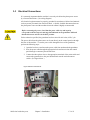
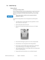
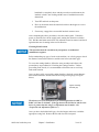
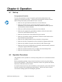
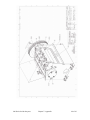
Beside-the-Press Granulators 810, 814, 818 Models Covered: GP, BP, X, MTG Part Number: MAN-CA039205 Bulletin Number: GRN1-625 Effective: August 1, 2012 Write Down Your Serial Numbers Here For Future Reference: _________________________ _________________________ _________________________ _________________________ _________________________ _________________________ We are committed to a continuing program of product improvement. Specifications, appearance, and dimensions described in this manual are subject to change without notice. DCN No. ____________ © Copyright 2013 All rights reserved. 800 Series beside-the-press Shipping Info Unpacking and Inspection You should inspect your granulator for possible shipping damage. Thoroughly check the equipment for any damage that might have occurred in transit, such as broken or loose wiring and components, loose hardware and mounting screws, etc. In the Event of Shipping Damage According to the contract terms and conditions of the Carrier, the responsibility of the Shipper ends at the time and place of shipment. Notify the transportation company’s local agent if you discover damage. Hold the damaged goods and packing material for the examining agent’s inspection. Do not return any goods before the transportation company’s inspection and authorization. File a claim with the transportation company. Substantiate the claim by referring to the agent’s report. A certified copy of our invoice is available upon request. The original Bill of Lading is attached to our original invoice. If the shipment was prepaid, write us for a receipted transportation bill. Advise customer service regarding your wish for assistance and to obtain an RMA (return material authorization) number. If the Shipment is Not Complete Check the packing list as back-ordered items are noted on the packing list. You should have: þ Bill of lading þ Packing list þ Operating and Installation packet þ Electrical schematic and panel layout drawings þ Component instruction manuals Re-inspect the container and packing material to see if you missed any smaller items during unpacking. If the Shipment is Not Correct If the shipment is not what you ordered, contact the shipping department immediately. For immediate assistance, please contact the correct facility located in the technical assistance section of this manual. Have the order number and item number available. Hold the items until you receive shipping instructions. 800 Series beside-the-press Returns Do not return any damaged or incorrect items until you receive shipping instructions from the shipping department. Credit Returns Prior to the return of any material, authorization must be given by the manufacturer. A RMA number will be assigned for the equipment to be returned. Reason for requesting the return must be given. ALL returned material purchased from the manufacturer returned is subject to 15% ($75.00 minimum) restocking charge. ALL returns are to be shipped prepaid. The invoice number and date or purchase order number and date must be supplied. No credit will be issued for material that is not within the manufacturer’s warranty period and/or in new and unused condition, suitable for resale. Warranty Returns Prior to the return of any material, authorization must be given by the manufacturer. A RMA number will be assigned for the equipment to be returned. Reason for requesting the return must be given. All returns are to be shipped prepaid. The invoice number and date or purchase order number and date must be supplied. After inspecting the material, a replacement or credit will be given at the manufacturer’s discretion. If the item is found to be defective in materials or workmanship, and it was manufactured by our company, purchased components are covered under their specific warranty terms. 800 Series beside-the-press Table of Contents CHAPTER 1: SAFETY ................................................................ 6 1-1 1-2 1-3 1-4 How to Use This Manual ............................................................................................. 6 Safety Symbols Used in this Manual ..................................................................... 6 General Safety Regulations ........................................................................................ 9 Responsibility .............................................................................................................. 9 Warnings and Precautions ........................................................................................ 10 CHAPTER 2: FUNCTIONAL DESCRIPTION ........................... 12 2-1 2-2 2-3 Models Covered and General Description ................................................................ 12 Typical Features and Components ........................................................................... 12 Safety Features ......................................................................................................... 13 CHAPTER 3: INSTALLATION.................................................. 15 3-1 3-2 3-3 3-4 Uncrating the Equipment........................................................................................... 15 Installing the Granulator ............................................................................................ 16 Electrical Connections ............................................................................................... 17 Initial Start-up ............................................................................................................ 18 CHAPTER 4: OPERATION....................................................... 21 4-1 4-2 4-3 Start-up ..................................................................................................................... 21 Operation Procedures ............................................................................................... 21 Shut-down ................................................................................................................. 22 CHAPTER 5: MAINTENANCE ................................................. 23 5-1 5-2 Preventative Maintenance Schedule ......................................................................... 23 Preventative and Corrective Maintenance ................................................................ 24 CHAPTER 6: TROUBLESHOOTING ....................................... 33 6-1 Introduction ............................................................................................................... 33 CHAPTER 7: APPENDIX.......................................................... 36 7-1 7-2 7-3 7-4 Technical Specifications ............................................................................................ 36 Drawings and Diagrams ............................................................................................ 37 Spare Parts List ......................................................................................................... 42 Technical Assistance ................................................................................................ 43 Parts and Service Department ............................................................................ 43 Sales and Contracting Department ..................................................................... 43 800 Series beside-the-press Chapter 1: Safety 1-1 How to Use This Manual Use this manual as a guide and reference for installing, operating, and maintaining your granulator. The purpose is to assist you in applying efficient, proven techniques that enhance equipment productivity. This manual covers only light corrective maintenance. No other maintenance should be undertaken without first contacting a service engineer. The Functional Description section outlines models covered, standard features, and safety features. Additional sections within the manual provide instructions for installation, preoperational procedures, operation, preventive maintenance, and corrective maintenance. The Installation chapter includes required data for receiving, unpacking, inspecting, and setup of the granulator. We can also provide the assistance of a factory-trained technician to help train your operator(s) for a nominal charge. This section includes instructions, checks, and adjustments that should be followed before commencing with operation of the granulator. These instructions are intended to supplement standard shop procedures performed at shift, daily, and weekly intervals. The Operation chapter includes a description of electrical and mechanical controls, in addition to information for operating the granulator safely and efficiently. The Maintenance chapter is intended to serve as a source of detailed assembly and disassembly instructions for those areas of the equipment requiring service. Preventive maintenance sections are included to ensure that your granulator provides excellent, long service. The Troubleshooting chapter serves as a guide for identification of most common problems. Potential problems are listed, along with possible causes and related solutions. The Appendix contains technical specifications, drawings, schematics, parts lists, and available options. A spare parts list with part numbers specific to your machine is provided with your shipping paperwork package. Refer to this section for a listing of spare parts for purchase. Have your serial number and model number ready when ordering. Safety Symbols Used in this Manual The following safety alert symbols are used to alert you to potential personal injury hazards. Obey all safety messages that follow these symbols to avoid possible injury or death. DANGER indicates an imminently hazardous situation that, if not avoided, will result in death or serious injury. WARNING indicates a potentially hazardous situation or practice that, if not avoided, could result in death or serious injury. CAUTION indicates a potentially hazardous situation or practice that, if not avoided, may result in minor or moderate injury or in property damage. 800 Series beside-the-press Chapter 1: Safety 6 of 43 Figure 1: Safety Tags and warning features Hazard Alert Symbol 800 Series beside-the-press Description/Explanation Preventative Maintenance High Voltage Hazard. The electrical enclosure is supplied with 3-phase electrical power. Use caution when using or maintaining this product. Every six months inspect all electrical connections for secure attachment. For further information see the Maintenance Chapter in this manual Hands could be exposed to a crushing movement. Every month inspect the shears/blades for any type of wear. For further information see the Maintenance Chapter in this manual. When equipped with belts and sheaves, hands could become entangled. Every month inspect the belt(s) for any type of wear. For further information see the Maintenance Chapter in this manual. Hands can become entangled or cut if they enter the danger zone of gears or cutting shears. Every month inspect the shears/blades for any type of wear. For further information see the Maintenance Chapter in this manual. The unit can produce continuous noise above 85 dBA and/or produce projectiles under normal operating conditions. Always wear eye and ear protection when the machine is in operation or performing maintenance. Chapter 1: Safety 7 of 43 Mandatory Symbol Description/Explanation Read Operators Manual. This equipment must be operated and maintained by properly trained personnel. The information contained within this manual must be read and understood prior to operating this equipment. Lock Out. This equipment is operated with 3-phase electrical power. Therefore, when performing any maintenance operations we recommend following the local standards for performing a lock-out/tag-out procedure. Wear Safety Gloves. This equipment operates with sharp blades and rotors. We recommend that technicians use safety gloves while performing maintenance to protect hands from being exposed to these sharp surfaces. Wear ear and eye protection. This unit may produce loud and continuous noise and may produce projectiles. Do not reach into unit. Reaching into a unit is prohibited while the unit is in operation and may cause serious injury or death. 800 Series beside-the-press Chapter 1: Safety 8 of 43 1-2 General Safety Regulations This machine uses knives for the performance of its intended use. Consequently, it can be a dangerous machine to operate and maintain unless these safety regulations are followed. These regulations should be read, understood and periodically reviewed by all personnel involved in any way with this machine. Never operate or jog the rotor unless the cutting chamber’s covers, discharge chute, and guards are in place and secure. Do not circumvent the safety interlocks. Never operate the machine or jog the rotor unless the cutting chamber covers, discharge chute, or any guards or covers are in place and secure. Do not circumvent the safety interlocks. Prior to clearing a jam or performing any maintenance, the motor should be turned off and electrically locked out. Be sure that the rotor has come to a stop. Hands must not be inserted into the machine to clear the jam. Do not extend any part of the body into feed roll openings or discharge area unless the motors are electrically locked out and the rotor and feed rolls are motionless. Never extend fingers through holes in the screen. Be sure that the v-belts are properly aligned and that tension is at its maximum. Extreme care should be taken to see that all bolts are properly tightened at all times. During the operation of the machine, rotor knife bolts may come loose. Although fine threads are used on the rotor knife bolts, you should inspect the tightness of the bolts frequently. This machine is designed for the granulation of plastic materials. Do not feed any other materials into the machine. 1-3 Responsibility These machines are constructed for maximum operator safety when used under standard operating conditions and when recommended instructions are followed in the maintenance and operation of the machine. All personnel engaged in the use of the machine should become familiar with its operation as described in this manual. Proper operation of the machine promotes safety for the operator and all workers in its vicinity. Becoming familiar with materials, inspection, speed limitations, screens, guard maintenance, and total user responsibility will assist you in learning potential areas in need of observation for danger. Each individual must take responsibility for observing the prescribed safety rules as outlined. All caution, warning and danger signs must be observed and obeyed. All actual or potential danger areas must be reported to your immediate supervisor. 800 Series beside-the-press Chapter 1: Safety 9 of 43 1-4 Warnings and Precautions Our granulators are designed to provide safe and reliable operation when installed and operated within design specifications, following national and local safety codes. To avoid possible personal injury or equipment damage when installing, operating, or maintaining this granulator, use good judgment and follow these safe practices: þ LEARN AND OBEY your company’s safety policy regarding granulating equipment. þ MOVING OR LIFTING THE GRANULATOR: Although our equipment is built and engineered for great ruggedness in operation, care must be taken when moving the machine along the floor or lifting it. Damage may occur to sheet metal covers, electrical cabinets, or small brackets if pressure is applied to them when moving the granulator. When lifting the granulator, be certain of total machine weight and the capability of the lifting equipment. (See the Granulator Specification Sheets for machine weights and dimensions.) þ GRANULATOR LOCATION: Adequate area for routine maintenance should be provided in order to open the machine for knife, screen, or cleanout service. Proper service area clearances also should allow people who are working on the machine to be clearly visible to others, thereby reducing potential safety hazards. þ SAFE HOUSEKEEPING: The work area must be kept clean and uncluttered during periods of operation or maintenance. No hand tools or other metal objects should be left on or around the machine. Any tools or other metal objects that mistakenly fall into the hopper feed opening can cause severe damage to internal cutting chamber, rotor and screen components. þ SAFETY GLASSES OR A FACE SHIELD MUST ALWAYS BE WORN when servicing or operating the machine. Although our machines are designed for the maximum in fly back control, caution must be used when operating near the hopper feed opening in order to guard against unexpected material fly back. þ EAR PROTECTION may be required when operating the machine during granulation of very hard or noisy materials. The Occupational Safety and Health Act of 1970 has established guidelines for Permissible Noise Exposures (OSHA 1910.95) that should be followed. þ NEVER attempt to operate the granulator unless it is fully assembled with all guards and interlocks in place and functional. þ OBSERVE all danger, warning, caution and safety labels on the equipment. þ Upon completion of any machine maintenance, be certain ALL SAFETY GUARDS AND COVERS are securely and properly fastened prior to resuming machine operation. All fasteners must be in place and properly tightened. ANY SHORTCUTS MAY RESULT IN INJURY TO PERSONNEL OR DAMAGE TO EQUIPMENT. þ NEVER wear any loose fitting clothes, neckties, or dangling items such as earrings, belts, or shoestrings. Jewelry, such as wristwatches, bracelets, or rings should NEVER be worn. Long hair must be tied back or placed in a tight fitting hairnet. NEVER lean against or rest hands or feet on the granulator when it is in operation or open for maintenance. NEVER stand on the granulator when it is in operation. 800 Series beside-the-press Chapter 1: Safety 10 of 43 þ ROTATION OF MOTORS: The correct rotating direction for the granulator motor is clearly marked on the machine. Always check for proper rotation of motors. Incorrect rotation direction can cause severe damage. þ ELECTRICAL GROUNDING: All electrical equipment on the granulator must be grounded in accordance to all local codes and Article 250 of the National Electric Code. þ ALWAYS DISCONNECT AND LOCKOUT the main electrical power to the granulator before performing any service. þ SAFETY INTERLOCKS MUST NOT BE BYPASSED. The mechanical and electrical safety interlocks ensure the safety of personnel. They should never be tampered with or removed for ANY reason. They should be checked frequently by a qualified mechanic for proper operation. þ NEVER modify the machine configuration or any individual component without written notice from the factory. For further information on granulator safety, installation and operation, see the American National Standard for Plastics Machinery⎯Granulators, Pelletizers, and Dicers Used for Size Reduction of Plastics⎯Construction, Care, and Use. ANSI B151.11-1982. We have long recognized the importance of safety and have designed and manufactured our equipment with operator safety as a prime consideration. We expect you, as a user, to abide by the foregoing recommendations in order to make operator safety a reality. 800 Series beside-the-press Chapter 1: Safety 11 of 43 2 1 Chapter 2: Functional Description 2-1 Models Covered and General Description The models covered in this operational manual include, from the 800 Series Beside-thePress Granulators, GP810, GP814, and GP818. This family of granulators has been designed to granulate plastic material such as sprues, runners, and small reject parts. The granulator is comprised of an in-feed hopper into which the material to be granulated is fed, mounted on a cutting chamber in which a series of rotary and bed knives reduce the material to granules, the size of which is determined by the screen holes. The granules fall and collect in the bin below. The operation of the granulator is controlled by a control panel and powered by an electric motor. 2-2 Typical Features and Components Main Components of Standard Granulators Please refer to the following list and figure. 1. In-feed hopper 2. Cutting chamber 3. Bin for granulated material 4. Belt drive 5. Control panel 6. Electric motor 5 1 4 2 6 3 800 Series beside-the-press Chapter 2: Functional Description 12 of 43 Optional Equipment The 800 Series Beside-the-Press granulators offer the following options: • Conveyor • Other screen hole sizes • Blower/airveying system • Vacuum bin • Special operating voltages Technical Data In-feed Front or top entry In-feed hopper For manual feeding Cutting chamber Upright bolted type Rotor 3-knife rotor w/ lateral disks Cutting system Scissor action with double angle cutting Knives Tool steel Refer to Drawings and Diagrams chapter for more information. 2-3 Safety Features The granulators are equipped with safety features intended to protect personnel and the granulator. DO NOT remove or tamper with such equipment. Safety Features Fitted on Granulator All moving drive parts, including the two pulleys and the belt, are contained in a guard, which may only be removed using specific tools and cannot be fixed in the correct position without special fastenings. Always make sure that the guard is in position before starting the granulator! The upper part of the cutting chamber is protected by the feed hopper, used to insert material to be granulated, while the lower part is protected by the screen and screen support. These components are fixed by a screw knob; unscrewing releases a safety switch key (see figure below), which cuts off the electric supply to the motor and causes the rotor to stop. The method of opening the granulator has been designed to restrict the operator access, which allows the rotor and all moving knives to stop completely. Allowing operating access more quickly could be dangerous because it is possible to make contact with the granulator knives while they are still rotating. 800 Series beside-the-press Chapter 2: Functional Description 13 of 43 Figure: Safety Switch Opening the Granulator The Start/Stop lighted push-button provided on the control panel (see figure below) is used to operate the granulator. The button must be pressed to stop the granulator and pulled out to start. Before performing any maintenance or opening the granulator, follow the procedure below: 1. Turn off the granulator using the provided push-button. 2. Turn the disconnect switch to OFF and lock out power. (If you cannot lock out power, then remove the power fuses in the control panel.) 3. Tag the machine as “Out of Service”. 4. Make sure the rotor has come to a complete stop. Wear protective gloves when exposed to knives! Figure: Control Panel Start/Stop PushButton Disconnect switch 800 Series beside-the-press Chapter 2: Functional Description 14 of 43 Chapter 3: Installation 3-1 Uncrating the Equipment Prepare in advance the site you have selected for installation of the granulator. Be sure the area the machine will occupy is clean, level, and free of obstruction. The selected site must have a floor rating to adequately support the weight of the machine. The granulator is mounted on a wooden skid and blocked and banded to secure it for shipment. All non-painted items subject to corrosion are coated with a quality rust preventative, and the machine is covered with heavy-duty polyethylene to protect it from moisture and dirt. Granulators are normally shipped completely assembled unless the size of the machine or an agreement for special shipping arrangements prompts partial assembly. If an inspection after shipment has revealed no shipping damage, unpack the unit by removing the polyethylene protective covering and banding. Remove the envelope with the parts list, assembly drawings, electrical schematics, and manual from the base evacuation area. You can now have the machine lifted from the skid. A forklift is ideal for this process, but make sure to properly position the forks between the casters and the centrally mounted evacuation pipe from the side of the machine (see figure below). Do not attempt to lift the granulator with a shaft or protruding member— ESPECIALLY THE HOPPER! 800 Series beside-the-press Chapter 3: Installation 15 of 43 3-2 Installing the Granulator Before lifting or moving the granulator, check the relative weight shown on the shipping papers. To facilitate the lifting operation using forklift trucks, the drop box has been removed from the granulator and is packed with any spare parts. When using a forklift to move the granulator, make sure it is suitable for the weight and dimensions of the granulator. When moving the machine, make sure NOT to damage delicate parts. To lift the machine with a forklift, place the carriage forks under its base (see below figures). When a forklift truck is not available, it is possible to use cables or belts provided that they are strong enough to support the weight of the granulator to carry out the lifting procedure. When moving the granulator, the load must remain in the horizontal position, regardless of the type of equipment used. Positioning the Granulator Make sure that the base supporting the granulator is solid and completely level. The granulator needs be supported without being subject to vibration, and it is recommended that the floor be reinforced concrete with a very smooth surface. Place the granulator in an area large enough to allow sufficient space on all sides for the operator to carry out maintenance. Although the granulator controls and electrical components comply with CE and NEMA codes and regulations, the machine must be placed in an area free of humidity, dampness, and water. The proper environment for a granulator is a weatherproof, covered, in-door area where water cannot collect on the floor. Once the granulator is in position, the front panel must be opened in order to insert the bin as shown in the figure below. 800 Series beside-the-press Chapter 3: Installation 16 of 43 3-3 Electrical Connections It is extremely important that the machine is correctly wired into the plant power source by a licensed electrician. (See wiring diagram.) All electrical equipment must be properly grounded in accordance with local and national codes to protect personnel from electrical shock. A fusible, lockable disconnect between the plant power source and the machine electrical cabinet is highly recommended. Before connecting the power, check that the power cable size and capacity corresponds to the horsepower and amp load indicated on the granulator label and that the disconnect switch is in the OFF position. Unless otherwise specified, the granulator has been wired for 480 volts, 60 Hz, 3 ph. The power cable from the plant source can be run directly to the control panel or through the base of the machine. To run the power cable through the base of the granulator, perform the following steps: 1. Open the back cover and insert the power cable from underneath the granulator. 2. Pass the power cable through the appropriate hole and insert it into the control panel through a connector placed at the base. 3. Connect the three-phase wires to the appropriate terminals of the main switch and connect the ground wire to the provided terminal near the main disconnect switch. (See figure below.) Figure: Electrical Connections 800 Series beside-the-press Chapter 3: Installation 17 of 43 3-4 Initial Start-up Start-up Checks Checking the Cutting Chamber Before starting the granulator, open the cutting chamber to ensure that no foreign objects have fallen in during transportation and installation. The use of heavy gloves is recommended to avoid injury when exposed to knives in the cutting chamber. This operation must be carried out by an operator/mechanical maintenance engineer. Check that the cutting chamber is free of foreign objects by following these steps: 1. Turn OFF and lock out the machine power to the granulator or remove fuses from the main control panel. 2. Open the front panel and remove the bin. 3. Unscrew the screw knob and carefully lower the screen. (See figure below.) 4. Pivot back the feed hopper to gain free access to the cutting chamber. 5. Check that there are no foreign objects in the cutting chamber. 6. Check to make sure the bed knife and rotor knife bolts are at the proper torque and the knife gap is set according to the specifications. 7. After completing the checks, close the hopper and screen and fasten them with the corresponding knob. 8. Reinsert the bin and close both the rear cover and the front panel. 800 Series beside-the-press Chapter 3: Installation 18 of 43 9. Remove the drive belt guard by unscrewing the ten (10) fastening screws. 10. Manually give the rotor at least one complete turn using the rotor pulley. 11. If there are no warning noises or signs of friction, then the cutting chamber is completely clear. Replace the belt guard, remove lock out devices, and turn power ON. Checking Rotation Direction Check to make sure the direction of the rotor is correct using the following steps: 1. Turn the main disconnect switch to ON. 2. Pull the Start button until the motor comes up to speed. 3. Push the button to stop the granulator motor. 4. Using the appropriate window, check that the rotor direction corresponds to that shown on the arrow label located above the guard. If the rotation direction is correct, the granulator is ready for use. If the rotation direction is incorrect, reverse the rotor direction using the following steps: A LICENSED ELECTRICIAN must carry out this operation! 1. Disconnect and lock out the power to the machine at the incoming power source. If the disconnect is not lockable, remove the fuses. 2. Reverse any two of the three power line conductors to the machine. If there is more than one motor on the machine and only one is turning in the wrong direction, reverse any two of the three line conductors at the overload relay for that motor. 3. Unlock the power and switch the electrical disconnect switch to ON. (Replace the fuses if necessary.) 4. Re-check the rotation direction of the motors. Test the Interlock Switch With the cutting chamber and screen cradle closed and power ON, perform the following tests: 1. Push the Start button to start the granulator. 2. With the granulator running, loosen the hand knob on the front access door to verify the safety interlock switch shuts the machine off. If the 800 Series beside-the-press Chapter 3: Installation 19 of 43 hand knob is completely loose and the power does not disconnect, the interlock switch is not working and the cause of malfunction must be determined. 3. Turn OFF and lock out the power. 4. Have an electrician check the interlock switch on the hopper to correct the malfunction. 5. If necessary, engage the screen cradle interlock actuator screw. After completing the above procedures, close the control panel. Unlock the power or return the fuses in the supply panel, turning the disconnect switch to ON. Pull the start button and release only when the motor has started, and check again that the rotor is turning in the correct direction. Checking Knife Position This operation must be carried out by an operator or mechanical maintenance engineer. Before undertaking any type of work on the machine, use a feeler gauge to check the distance between the bed knives and the rotor knives (the knife gap). To access the cutting chamber, follow the same procedure and observe the precautionary steps outlined in “Checking the Cutting Chamber.” Before proceeding to the checks, it is recommended to block the rotor to avoid any inadvertent rotation. Once you have safely accessed the cutting chamber, check the current distance between the bed knives and the rotor knives using a feeler gauge (see figure below). Figure: Checking the knife gap The distance set by the manufacturer for normal application is 0.006" to 0.008" (0.15 mm to 0.20 mm). If the gap between the bed knives and the rotor knives is greater than this range, an adjustment must be made. (See “Inspection and Adjustment of Knives”.) Once you have checked the knife gap, close the hopper and secure it with the appropriate swing bolt. Reinsert the bin and close the front panel. 800 Series beside-the-press Chapter 3: Installation 20 of 43 Chapter 4: Operation 4-1 Start-up Pre-operational Checklist To ensure the granulator is ready for operation, perform the outlined tasks in the following pre-operational checklist. All electrical and mechanical machine elements MUST be inspected and any defects MUST first be corrected. ü Make sure the operational manual has been read and followed. ü Make sure that all necessary personnel (granulator operators, cleanout, maintenance, service personnel) have been fully trained on machine operation and all machine safety mechanisms. ü Make sure sufficient location clearances have been allowed. ü Make sure the equipment is grounded in accordance with local codes and/or Article 250 of the National Electric Code. ü Make sure all motors have been checked for proper rotation. ü Make sure all machine controls, push-buttons, and limit switch interlocks have been checked for proper function. ü Make sure the cutting chamber has been checked for foreign matter. ü Make sure the drive components have been checked for alignment and tension. ü Make sure the machine is properly closed with all visible fasteners tight. ü Make sure all accessory components are electrically and mechanically connected with proper support and fasteners tightened. ü Make sure electrical enclosure boxes are tightly closed and clamped shut. ü Make sure all personnel are clear of the machine. 4-2 Operation Procedures The granulator can be operated in a vertical top-feed position or in a horizontal front-feed position. Before starting the granulator, always check for and remove tools or any other objects placed on the granulator. Turn the Power disconnect switch to ON, pull the Start button, and release it when the motor has started. It is normal for the motor not to start immediately, as the electronic system must check all the micro switches before enabling start-up procedures. Wait for the electric motor to reach normal rotating speed before feeding the granulator. 800 Series beside-the-press Chapter 4: Operation 21 of 43 Never push material into the hopper with hands! If the hopper becomes blocked, the granulator must be turned OFF, and the power must be locked out or the fuses removed. 4-3 Shut-down Before stopping the granulator for the end of a working shift or for any other reason, stop feeding the material and leave the granulator running for several minutes to allow the cutting chamber to completely granulate and empty the material inside. Press the lighted Start/Stop button to immediately turn off the granulator. If the granulator stalls frequently during use, it may be necessary to adjust the calibration of the “overload.” (Refer to the values shown in the electrical diagram.) 800 Series beside-the-press Chapter 4: Operation 22 of 43 Chapter 5: Maintenance 5-1 Preventative Maintenance Schedule Before carrying out any work on the granulator, carefully read the instructions provided in this manual. Only specialists and competent personnel should carry out these operations. All maintenance work must be carried out with the granulator switched OFF and with the power supply disconnected and locked out. Conduct that is not in accordance with safety instructions outlined in this manual may pose a threat to both personnel and equipment. Once the maintenance work is completed and before re-starting the granulator, make sure to check the following: ü Any parts that may have been replaced and/or tools that have been used are removed from the granulator. ü All safety equipment is in proper working condition. Periodic Maintenance Schedule Mechanical Check Frequency Knife clearance and wear Weekly Rotor knife retaining screws for tightness Weekly Downstroke bed knife and shield retaining screws for tightness Weekly Upstroke bed knife retaining screws for tightness Weekly Screen cradle arm screws for tightness Weekly In-feed chute and cutting chamber screws for tightness Monthly After the granulator has been used for the first day, adjust the drive belt tension. Correct tension for use should be the minimum at which the belt does not slip. Make sure the pulleys are correctly aligned. 800 Series beside-the-press Chapter 5: Maintenance 23 of 43 5-2 Preventative and Corrective Maintenance Monthly Maintenance Operations Drive Belt Tension This operation should be carried out by an operator or mechanical maintenance engineer. For the granulator to function correctly, it is extremely important that the drive belt is always tight. Correct tension reduces the load of the rotor bearings and minimizes wear and stretching of the belt. To check and adjust belt tension, use the following procedure: 1. Turn OFF the machine and lock out power by using the disconnect switch, or remove the fuses from the electrical control panel. 2. Remove the belt guard by unscrewing the ten (10) screws that hold it in place. 3. Open the front panel. 4. Remove the bin. 5. Open the rear panel. 6. Loosen the nuts that lock the motor base slide. 7. Loosen the tie rod. 8. Adjust the belt tension by turning the tie rods forward. 9. Turn the tie rod to bring the motor square to the belt axis. 10. After the adjustment is made, lock the nuts back in place and close the rear panel, refitting the proper locking latch. 11. Reinsert the bin and close the front panel. 12. Refit the belt guard and unlock the power or replace the fuses in the control panel. Proper Belt Tension Measure the belt span and divide by 64 to get the allowable belt deflection. With a belt gauge, measure the force it takes to deflect the belt the amount calculated. Check your belt gauge’s instructions for proper scale settings. Belt tension gauges are available from the customer service department. Compare the gauge reading to chart value for the belt cross-section used (see table below.). 800 Series beside-the-press Chapter 5: Maintenance 24 of 43 1. Verify that the alignment of the pulley is correct. Utilizing a straightedge of sufficient length to span from one pulley to the other, place it along the sides of both pulleys. The entire face of each pulley should fully contact the straightedge. 2. Measure the belt SPAN with a measuring tape. Record this dimension in your note book. 3. Using the deflection tester, apply a perpendicular force at the midpoint of any one of the belts to deflect the belt 1/64th of an inch. 4. Calculate the deflection force: FORCE[Lb]= SPAN[IN] X (1/64)[Lb/IN] 5. Identify the belt type and measure the small sheave diameter. Look up the proper model belt deflection force table and find out what the force is supposed to be. 6. The motor position should be adjusted until the actual deflection force matches the force listed in the table. BELT SPAN 7. In no case should the belts be over tensioned, as this can significantly reduce belt and/or bearing life. 800 Series beside-the-press Chapter 5: Maintenance 25 of 43 BELT CROSS SECTION DEFLECTION FORCE (Lbs) SMALL SHEAVE DIAMETER RANGE 3VX 3.65-‐4.12 3.7 4.50-‐5.60 6.4 7 7.5 Belt Replacement It is very important to replace all belts at the same time! If the drive belts have to be replaced, follow the procedure from “Drive Belt Tension” through Step 6. When the point is reached, release the belt from tension by fully unscrewing the tie rods. Slip off the belts and replace them with new ones. Continue with the procedure for adjusting the belt tension. Removal and Replacement of the Screen A qualified operator/maintenance mechanic should carry out this procedure! 1. Switch the machine OFF and lock out power by turning the disconnect switch or remove the fuses from the main control panel. 2. Open the front panel. 3. Remove the bin. 4. Remove the screw knob that holds the hopper on top of the cutting chamber. Carefully lower the screen cradle assembly, and resting it on the base. 5. Remove the screen, keeping it in a horizontal position (see figure below). 6. Replace the screen with a new one; tighten the screw knob, reposition the bin and close the front panel. Unlock the power and turn the machine ON. 800 Series beside-the-press Chapter 5: Maintenance 26 of 43 Figure: Removing the screen Inspection and Adjustment of Knives This operation must be performed by a qualified operator or mechanical maintenance technician. Before carrying out any maintenance on the cutting chamber, the operator must put on work gloves thick enough to avoid injury to the hands while touching sharp parts and the cutting edges of blades. To inspect the blades, remove the screen following the procedure in “Removal and Replacement of Screen.” Then proceed as follows: 1. Open the rear-closing panel by releasing the locking latch. 2. Pivot the in-feed hopper completely back to gain clear access to the cutting chamber. 3. Clear any process material or foreign objects between the knives. 4. Turn the rotor slowly until the first row of rotor knives are in close proximity to the bed knife cutting edge. Turn the rotor backwards; keep hands and fingers from directly contacting sharp knife edges. 5. Using a feeler gauge, measure the gap between the rotor and knife cutting edges. Check each rotor knife to find the “high knife”, or the knife that measures the smallest gap. If the gap is substantially greater than the specified 0.006 in. to 0.008 in. (0.15 mm to 0.2 mm), the knives need readjustment. 6. Loosen the bed knife shield; hold down the screws and remove the shield. 7. Leave the screws that hold the bed knife just tight enough to allow the bed knife to move. 8. Loosen the adjustment screws and lock nuts. 800 Series beside-the-press Chapter 5: Maintenance 27 of 43 9. Insert a 0.006 in. to 0.008 in. (0.15 mm to 0.2 mm) thickness gauge between the cutting edge of the bed knife and that of the high rotor knife. 10. Adjust the bed knife into the rotor knife using the adjustment screws. Make sure to leave enough space for the thickness gauge to move. Check that the distance between the fixed and rotating knife is the same at both ends of each knife. Move the bed knife using the push adjusting screws a little at a time on each end. 11. When adjustment is complete, tighten the lock nuts on the adjustment screws. 12. Torque the bed knife and bed knife shield bolts to 95 lbs/ft. (13 kg/m, 128 Nm) using a torque wrench. 13. Repeat the steps 4-11 to adjust the rear (or downstroke) bed knife. Turn the rotor slowly for one complete revolution, checking the exact distance between all the rotary knives and bed knives. 14. Close the hopper and replace the screen and screen cradle, securing them in place using the swing bolt provided. 15. Close the front and rear doors and unlock the power or replace the fuses in the control panel. Turn the disconnect switch to ON. Figure: Inspection of Knives Bed knife locking bolts Rotor knife locking bolts Bed knife adjusting screws 800 Series beside-the-press Chapter 5: Maintenance 28 of 43 Removing and Replacing Bed Knives This procedure should be performed only by a qualified operator or maintenance engineer. Protective gloves must be worn to avoid injury when handling the cutting knives! To remove and replace bed knives, use the following procedure. 1. Open the granulator by following the steps “Removal and Replacement of the Screen.” 2. Open the rear-closing panel by releasing the locking latch. 3. Pivot the in-feed hopper completely back to gain clear access to the cutting chamber; clear any process material or foreign objects from between the knives. 4. Rotate the rotor so that the rotor knives will not interfere with the removal of the bed knife. Using a wooden block, block the rotor to prevent it from rotating while removing the knives. 5. Loosen the lock nuts and back off the adjustment screws. 6. Loosen and remove the bed knife shield bolts and remove the shield positioned above the knife. The remaining bed knife bolts and bed knife may now be removed. 7. Perform the above steps to remove the rear (upstroke) bed knife as well. Before replacing the bed knife with new or sharpened knives, whip off the knife seats on the knife block, being sure to clean off all process material. The tapped holes in the knife block (used for holding the knives in place) should be clear of any dirt, oil, or process material. 8. Install new or sharpened bed knives on each knife seat, making sure that the rotor is blocked to prevent it from rotating while installing each knife. Be sure to place the bed knives in the correct positions: a. The rear (upstroke) bed knife must be placed with the extended cutting edge on the bottom. b. The front (downstroke) bed knife should be placed with the cutting edge on the top. 9. Before re-installing the knife bolts, wipe them clean with a light oildamp cloth. Do not leave an oil film on the bolt since lubrication can adversely affect the stress on the bolt when torqued to the specified values. It is recommended that the knife bolts be replaced with each new set of knives. This will reduce the risk of bolt failure due to overstretching. Always use the specified replacement bolts. 800 Series beside-the-press Chapter 5: Maintenance 29 of 43 10. Tighten the bolts that hold just the bed knife enough to keep the knife in place at the same time allowing the adjusting screws to move the knife forward. 11. Adjust the knife gaps with the rotor knives following steps 8-12 in “Inspection and Adjustment of Knives.” 12. Replace the shields in position above the bed knives. The shield on the front (downstroke) bed knife should be positioned so that the inside edge is set back approximately 1/32" from the cutting edge below it. Replace the remaining bolts and torque. 13. Close the machine while following steps 12-14 in “Inspection and Adjustment of Knives.” Removal and Replacement of Rotating Blades Only a qualified operator or maintenance engineer should perform this operation. Protective gloves MUST be worn to avoid injury when handling the cutting knives. To remove and replace rotor knives, complete the following procedure: 1. Open the granulator following the steps in “Removal and Replacement of the Screen.” 2. Open the rear-closing panel by releasing the locking latch. 3. Pivot the in-feed hopper completely back to gain clear access to the cutting chamber; clear any process material or foreign objects from between the knives. 4. Rotate the rotor so that the knife bolts are in a convenient position to remove the bolts with the appropriate wrench. Using a wooden block, block the rotor to prevent it from rotating while removing the knives or after a knife as been removed. 5. Loosen and remove the knife bolts and lift the knife off the knife seat. Remove the knife from the cutting chamber. 6. Perform the above steps until all the rotor knives are removed. Before replacing the rotor with new or sharpened knives, wipe the knife seats on the rotor, making sure to clean off all process material. The tapped holes in the rotor (used for holding the knives in place) should be clear of any dirt, oil, or process material. 7. Loosen the bed knife bolts and adjusting screws, and pull back the bed knife so the rotor knives will not collide as they are installed and rotated. 8. Install knew or sharpened knives on each knife seat, making sure that the rotor is still blocked to prevent it from rotating. 800 Series beside-the-press Chapter 5: Maintenance 30 of 43 9. Before re-installing the knife bolts, wipe them clean with a light, oildamped cloth. Do not leave an oil film on the bolt since lubrication can adversely affect the stress on the bolt when torqued to the specified values. It is recommended that the knife bolts be replaced with each new set of knives. This will reduce the risk of bolt failure due to overstretching. Always use the specified replacement bolts. 10. Tighten each set of the knife bolts, making sure that the knife is seated against the back heel in the rotor seat. Before setting the torque of the bolts, check that a 0.001" feeler gauge cannot fit between the heel and the back of the knife. 11. Torque the rotor knife bolts to 100 lbs/ft. (14 kg/m, 135 Nm). 12. Adjust the knife gap with the bed knives and close the machine, following steps 8-12 in “Inspection and Adjustment of Knives.” Specifications for Re-sharpening Bed Knives Every bed knife has two cutting edges, one on each side. When a blade becomes worn, the knives can be rotated. To regrind these knives, refer to Bed Knife Specifications. Replacement of these knives is necessary when their length fails below the recommended tolerance. Model X Y 810 2.43 in. 61.8 mm 2.75 in. 69.9 mm 814 818 Grind these surfaces only 20° .158", (4 mm) Minimum length, X New knife length, Y 800 Series beside-the-press Chapter 5: Maintenance 31 of 43 Specifications for Re-sharpening Rotor Knives All the rotor knives must be re-sharpened in sets. Each knife within a set must have a tolerance within 0.003" (0.05 mm) for the total height, heel to cutting edge. Greater variations within a set will result in improper knife gap settings and other operational problems. (See “Rotor Knife Specifications.”) Knives below the minimum dimension specified must not be used! Using knives below the specified minimum can cause interference resulting in serious damage to the rotor and cutting chamber. When using a surface grinder to re-sharpen the rotor or bed knives, it is not harmful to allow a few small nicks to remain on the cutting edge. Grinding the knife so that the cutting edge is free from all nicks can be wasteful. Figure: Rotor Knife Specifications 30° 20° .382” ± .003 (9.5 mm ± .05) Minimum Length 2.305” (58.5 mm) New Knife Length 2.480” (63 mm) 800 Series beside-the-press Chapter 5: Maintenance 32 of 43 Chapter 6: Troubleshooting 6-1 Introduction The utmost in safety precautions should be observed at all times when working on or around the machine and the electrical components. All normal trouble-shooting must be accomplished with the power off, line fuses removed, and with the machine tagged as out of service. The use of good quality test equipment cannot be over-emphasized when troubleshooting is indicated. Use a good ammeter that can measure at least twice the AC and DC current that can be encountered for the machine. Be sure that the voltmeter has at least minimum impedance of 5,000 OHMS-per-volt on AC and 20,000 OHMS-per-volt on DC scales. Popular combination meters, VOM and VTVM can be selected to provide the necessary functions. Before making haphazard substitutions and repairs when defective electrical components are malfunctioning, we recommend that you check the associated circuitry and assemblies for other defective devices. It is common to replace the obviously damaged component without actually locating the real cause of the trouble. Such hasty substitutions will only destroy the new component. Refer to wiring diagrams and schematics. Locating mechanical problems, should they occur, is relatively straightforward. When necessary, refer to the parts catalog section. 800 Series beside-the-press Chapter 6: Troubleshooting 33 of 43 General Problems Problem Overheating of bearings Knives moving in their seats Broken Knife Possible Cause Possible Remedy Dirt or contamination in the bearing Correct source of contamination Excessive belt tension Adjust belt tension No lubrication Check bearing seals May be foreign matter on the knives Carefully clean seat Knife screws loose Tighten screws with torque wrench at values specified Knife screws weakened Screws must not be used more than 6 times Improper re-sharpening Check knife grinding method used Extremely hard material Contact supplier Incorrect rotor direction Check rotor direction Foreign body in the cutting chamber Look for cause with operator Faulty fitting of screen Check assembly procedure Incorrect knife position Correct the gap or distance between bed knives and rotor knives Excessive knife wear Improper knife re-sharpening Check dimensions with figures included in this manual. Abrasive material Contact the supplier for special knives Incorrect fitting of screen Check that the screen is correctly seated in its rear position and that it fits perfectly at the front Abrasive material Contact the supplier for special knives Excessive in-feed material Reduce amount of material being fed to the machine Total or partial obstruction of the screen holes Remove the screen and clear the holes Insufficient belt tension Check and/or adjust belt tension Knives worn Replace with new knives Distance between the knives too small or large Check distance between knives Screen holes too small Increase screen hole diameter Failure of air conveying system or discharge system Check fan rotation and make sure pipes are not obstructed Abnormal screen wear Rotor jamming 800 Series beside-the-press Chapter 6: Troubleshooting 34 of 43 Electrical Problems Problem Machine stops for no apparent reason Electric motor does not start Motor starts but does not speed up or take a load Motor starts, but does not gain speed 800 Series beside-the-press Possible Cause Possible Remedy Safety switch has stopped power Check that the knobs that operate the safety switch are tightened No power Check fuses Overload failure Check amperage of electric motor Safety switch not working Check and replace Cutting chamber too full Empty cutting chamber Excessive drive belt tension Check belt tension and adjust Motor connected to power source incorrectly Reconnect correctly Defective starter winding Check current in each phase. If substantial difference between phases, contact motor manufacturer Bearing excessively worn Replace bearings Cutting chamber full Empty cutting chamber Chapter 6: Troubleshooting 35 of 43 Chapter 7: Appendix 7-1 Technical Specifications Overall Dimensions (CA039016) 800 Series beside-the-press Chapter 7: Appendix 36 of 43 7-2 Drawings and Diagrams Cutting Chamber—Vertical Cross Section (CA039060S2) 800 Series beside-the-press Chapter 7: Appendix 37 of 43 Cutting Chamber—Longitudinal Cross Section (CA039060S1) 800 Series beside-the-press Chapter 7: Appendix 38 of 43 Cutting Chamber—Front View (CA039060S3) Cutting Chamber—Rear View (CA039060S4) 800 Series beside-the-press Chapter 7: Appendix 39 of 43 800 Series beside-the-press Chapter 7: Appendix 40 of 43 Typical Wiring Diagram 800 Series beside-the-press Chapter 7: Appendix 41 of 43 7-3 Spare Parts List Recommended Spare Parts Item GP810 Quantity GP814 Quantity GP818 Quantity 3 9 2 8 8 1 2 2 4 1 3 12 2 10 10 1 2 2 4 1 3 15 2 10 10 1 2 2 4 1 Rotor Knife Rotor Knife Screw Bed Knife Bed Knife Screw Bed Knife Washer Screen Rotor Bearing Drive Belt Bed Knife Adj. Screw Interlock Switch Material HCHC GR 10.9 M12 x 40MM HCHC GR 10.9 M12 x 60MM Hardened Specify Hole Size Required 65MM Bore Qty. Depends on HP GR *When ordering a screen, always specify the diameter of the holes required. 800 Series beside-the-press Chapter 7: Appendix 42 of 43 7-4 Technical Assistance Parts and Service Department The ACS Customer Service Group will provide your company with genuine OEM quality parts manufactured to engineering design specifications, which will maximize your equipment’s performance and efficiency. To assist in expediting your phone or fax order, please have the model and serial number of your unit when you contact us. A customer replacement parts list is included in this manual for your convenience. ACS welcomes inquiries on all your parts needs and is dedicated to providing excellent customer service. For immediate assistance, please contact: • North, Central and South America, 8am – 5pm CST +1 (800) 483-3919 for drying, conveying, heating and cooling and automation. For size reduction: +1 (800) 229-2919. North America, emergencies after 5pm CST (847) 439-5855 North America email: [email protected] • Mexico, Central & South America Email: [email protected] • Europe, Middle East & Africa +48 22 390 9720 Email: [email protected] • India +91 21 35329112 Email: [email protected] • Asia/Australia +86 512 8717 1919 Email: [email protected] Sales and Contracting Department Our products are sold by a worldwide network of independent sales representatives. Contact our Sales Department for the name of the sales representative nearest you. Let us install your system. The Contract Department offers any or all of these services: project planning; system packages including drawings; equipment, labor, and construction materials; and union or non-union installations. For assistance with your sales or system contracting needs please Call: North, Central and South America +1 (262) 641-8600 or +1 (847) 273-7700 Monday–Friday, 8am–5pm CST • Europe/Middle East/Africa +48 22 390 9720 • India +91 21 35329112 • Asia/Australia +86 512 8717 1919 Facilities: ACS offers facilities around the world to service you no matter where you are located. For more information, please visit us at www.acscorporate.com United States: ACS Schaumburg- Corporate Facility 1100 E. Woodfield Road Suite 588 Schaumburg, IL 60173 Phone: + 1 847 273 7700 Fax: + 1 847 273 7804 ACS New Berlin- Manufacturing Facility th 2900 S. 160 Street New beside-the-press Berlin, WI 53151 800 Series Phone : +1 262 641 8600 Fax: + 1 262 641 8653 Asia/Australia: India ACS Suzhou 109 Xingpu Road SIP Suzhou, China 215126 Phone: + 86 8717 1919 Fax: +86 512 8717 1916 ACS India Gat No. 191/1, Sandbhor Complex Mhalunge, Chakan, Tal Khed, Dist. Pune 410501, India Phone: +91 21 35329112 Fax: + 91 20 40147576 Europe/Middle East/Africa: ACS Warsaw Ul. Działkowa 115 Chapter 7: Appendix 02-234 Warszawa Phone: + 48 22 390 9720 Fax: +48 22 390 9724 43 of 43