1
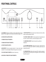
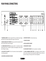
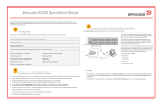
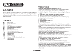
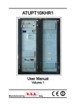
SP 101 AMPLIFIER
INTRODUCTION
CONTENTS
Congratulations on purchasing this Acoustic Solutions’ integrated amplifier.
It has been developed following an extensive research and development
program that has culminated in what we regard as an exceptional mid-range
hi-fi product.
Introduction
Safety Instructions
Front Panel Controls
Rear Panel connections
Installation and Position
Making the Connections
Using the Amplifier
Trouble Shooting
Specifications
Contact Details
Our aim when designing this product was to produce a visually appealing
unit which would look comparable to higher priced products, and give an
exceptional performance to match.
We trust that this amplifier will give you hours of listening pleasure, and
provide years of unparalleled performance. As with any new electrical product
please be patient and allow at least 36 hours use before all components
have acclimatised themselves to your surroundings, and found their optimum
working temperature. Please do not operate this product at high volume levels
immediately after switching on.
1
PAGE No.
1
2
3
4
5
6
7-10
11
12
12
SAFETY INSTRUCTIONS
CAUTION: To reduce the risk of electric shock, do not remove any cover.
NO USER-SERVICEABLE PARTS INSIDE, REFER ANY SERVICING TO
QUALIFIED SERVICE PERSONNEL.
UK MAINS PLUG DETAILS
IMPORTANT SAFETY INSTRUCTIONS
• The SP 101 is designed to operate on AC mains supply between 220
and 240 volts, 50 Hz.
• The wires in the mains lead are coloured in accordance with the
following code:
• Read and keep these instructions available for future reference.
• For indoor use only.
• The unit must only be connected to a suitable mains power supply using the
mains power lead provided.
• To reduce the risk of fire or electrical shock, do not expose this unit to rain
or moisture.
• The apparatus shall not be exposed to dripping or splashing.
• No objects filled with liquids, such as vases, shall be placed on the
apparatus.
• Unplug the unit from the wall socket during lightning storms and when it is
not going to be used for a long period of time.
• Take care that foreign objects do not enter, or liquids are not spilled, into
the enclosure through any openings. If this should happen, refer to qualified
service personnel before attempting to use.
• Ensure adequate ventilation - do not cover this unit with curtains, etc.
• Do not install near any heat source, such as radiators, or other equipment
that produces heat.
• Protect the mains power cable from being damaged.
• The SP 101 system is double insulated and does not require an earth
connection in the UK mains plug.
For your convenience a mains plug with a fuse (3 Amp) has been fitted to
this appliance. For your safety please observe the following information.
BLUE
BROWN
- NEUTRAL
- LIVE
• Under no circumstances should the Neutral or Live wires be connected
to the ‘E’ (Earth) terminal.
CAUTION
RISK OF ELECTRIC SHOCK!
DO NOT OPEN!
The lightning flash symbol with the arrowhead within an equilateral triangle is
intended to alert the user to the presence of uninsulated ‘dangerous voltage’
within the product’s enclosure that may be sufficient to constitute a risk of
electric shock to persons
The exclamation point within an equilateral triangle is intended to alert the user
to important operating and maintenance instructions in the service literature
relevant to this appliance.
This product complies with
European low voltage (73/23/
EEC) and electromagnetic
compatibility (89/336/EEC)
directives.
2
FRONT PANEL CONTROLS
1. LCD DISPLAY. Will give an indication of volume position and input source
selected. Will also display other menu features as described on pages (7-13).
9. FUNCTION BUTTON. Allows access to menu features such as bass, treble,
balance, loudness, speakers on/off etc.
2. PHONO INPUT SELECTOR SWITCH.
10. ROTARY CONTROL KNOB. This allows adjustment of parameters such
as volume, bass, treble, balance, loudness and speakers on/off etc.
3. TUNER INPUT SELECTOR SWITCH.
4. TAPE/AUX INPUT SELECTOR SWITCH.
5. CD INPUT SELECTOR SWITCH.
6. IR RECEPTOR. This can be used with optional 3 in 1 remote control which
is available. This controls Amplifier, DAB and CD player from one hand set.
7. DVD INPUT SELECTOR SWITCH. (stereo 2 channel only).
8. DAB DIGITAL TUNER INPUT SELECTOR SWITCH.
11. HEADPHONE SOCKET. Stereo 6.4mm jack for use with most
headphones.
12. LED POWER INDICATOR. Light will show green to indicate that the
SP101 is on. It will show red if the SP101 is in stand by mode set by the
optional remote control.
13. POWER BUTTON. Switches mains power on/off to internal components,
however please note that mains power is still applied to this unit even though
this switch may be off.
3
REAR PANEL CONNECTIONS
1. WARNING LABELS. Please be aware that this unit contains high voltages,
and should not be opened, please refer to page 2 of this manual.
2. MAINS CABLE INLET POSITION. Please ensure that this cable strain relief
bush is intact and has not been damaged.
6. DVD INPUT SOCKET. (2 channel stereo only).
7. CD INPUT SOCKET.
8. TAPE/ AUX INPUT SOCKET.
3. LOUDSPEAKER OUTPUTS. Please ensure that +/- connections are made
properly between rear of the SP101 amplifier and loudspeakers. Ensure wires
are not frayed or touching.
9. TUNER INPUT SOCKET.
4. LINE OUTPUT SOCKETS. This is for connection to external amplification
or recording equipment.
11. PHONO TERMINAL EARTH POST. It is necessary to provide a chassis
earth connection between the turntable and the amplifier. Failure to do this will
result in a buzzing or humming noise from the loudspeakers.
5. DAB DIGITAL RADIO INPUT SOCKET.
10. PHONO INPUT SOCKET. For the connection of a turntable.
4
INSTALLATION AND POSITION
This amplifier should be positioned on a flat stable surface. We would
recommend that the position of your hi-fi equipment should be chosen carefully
to provide adequate protection for this device, but also provide an attractive
showcase for your investment. Hi-fi equipment is not designed to be moved
often, therefore it is recommended that a permanent home for your hi-fi be
achieved as soon as is possible.
As this amplifier is fitted with a powerful mains transformer, it is not
recommended that sensitive audio equipment such as turntables or cassette
decks be placed immediately next to it. Do not place the SP101 in areas of
direct sunlight, nor place it adjacent to a radiator or other heating appliances.
Like all amplifiers the SP101 will generate a modest amount of heat. The
cooling of this device is reliant upon the flow of air through the chassis grilles
which are located on the top and bottom of the cabinet. Care should be taken
not to cover these grilles with items such as rugs, covers or curtains which will
restrict this air flow. Do not place the amplifier on a soft surface as this may
result in the bottom grille becoming restricted, and as a result may lead to
over-heating.
Do not place records, tapes or compact discs on top of the unit. Be aware that
after prolonged usage the chassis of this unit will become hot.
Never allow the amplifier to come into contact with water or liquids, and ensure
that small objects do not fall through the ventilation grilles. In the event of this
happening, disconnect the wall plug form the mains supply immediately, and
contact your local dealer for service advice.
There will be a corresponding pair of terminals on the rear of suitable
loudspeakers. These terminals should be connected together with adequate
quality speaker cables, taking care that the red terminal on the amplifier is
connected to the red terminal on the loudspeaker. The same process should
occur for the black terminals. Care should be taken to ensure that no wires
have become frayed during this process, and subsequently could be touching
each other. This will cause a short circuit on the output stage of the amplifier,
and will result in a poor or distorted sound. Failure to rectify this problem may
result in long term damage to this unit.
Position the loudspeakers a suitable distance away form the amplifier, gaining
enough distance to allow the stereo image to be achieved. Having the
loudspeakers too close to each other will not allow you to fully define the stereo
content of music played through the system, plus may result in poor sound
due to the cancellation properties that sometimes exist when in this state. It
is not ideal to place loudspakers in the corners of a room as this will normally
colour the audible content of the music with a lift in bass content. Although it
is sometimes desirable to increase the bass response of your system, this
can lead to a ‘boomy’ bass which is not always desirable, and can be hard to
control. It should also be noted that firing loudspeakers onto a hard flat surface
can cause mid range and high frequency colouration as reflected sound
becomes part of the audible sound. This can lead to a harshness, or dead
spots through cancellation.
The best sound is always subjective to the listener, therefore we suggest you
arrange your hi-fi to suit your own listening tastes, and sit back and enjoy the
fruits of your labour.
Do not position the power cable such that it can be walked upon, or damaged
by regular traffic. Ensure that all other interconnecting cables such as speaker
cables or ancillary equipment leads, are stowed safely behind the unit, and
cannot be easily snagged or kicked thus causing possible damage to the unit.
Ensure that all interconnetion cables have been fitted correctly, and that
polarity has been maintained. This is especially important when connecting
loudspeakers to this amplifier. On the rear panel, binding post speaker outputs
are provided. These are coloured red for positive, and black for negative.
5
MAKING THE CONNECTIONS
6
USING THE AMPLIFIER
When you unpack the amplifier from the box, all music settings will be at
default values. These can be altered according to your listening tastes; these
new settings will be retained within the memory of the amplifier and will remain
set even after switchiing off this system.
CHANGING THE INPUT LISTENING SOURCE
THE FUNCTION MENU
This SP101 amplifier is fitted with a digital user interface which allows
complete control of the features of this amplifier.
The menu structure of this product is as follows:
This amplifier is fitted with 6 inputs for connections to the following external
equipment:
1.
• Phono (turntable)
• Tuner (AM + FM)
• Tape / Aux line input source
• CD
• DVD (stereo only)
• DAB tuner
2.
3.
These will be connected to the rear panel as indicated in the connection
diagram on the previous page.
To change which input source is listened to, press once the switch below the
corresponding piece of equipment which is required. Pressing another input
source switch will change which music source is listened to.
4.
The LCD display will show the corresponding input source selected on line
2 of the display, this will change according to which input selector switch is
pressed.
5.
6.
7
VOLUME CONTROL DEFAULT SETTING
The default setting for the user interface control is the ‘volume’ setting. This will
be displayed on line one of the LCD display as a numeric dB value.
BASS CONTROL
This amplifier is fitted with a bass control which offers +/-14dB attenuation
around the centre bass frequency of 100Hz, and +/-3dB across the frequency
range of 45Hz to 259Hz.
To alter this bass control press the function button once, this will change the
LCD display for bass control.
Note: dB values are a professional indication of the amplitude of an audio
signal with full or maximum output achieved normally at 0dB. You will notice
the LCD display on this amplifier will read minus dB figures up until zero which
will indicate maximum output.
The rotary control (10) can be turned both clockwise and anticlockwise to alter
the dB signal. There are 64 steps in total which range from -78.75dB for nil
volume, to 0dB which will provide maximum output.
We have also provided a bar graph display on line 2 of the LCD display, which
indicates the status of the volume control when rotated. There are 16 squares
(
) which run from left to right and will change pro-rata to the increase or
decrease in volume
This display will replace the input music source description on line 2 of the LCD
display while the volume control is operated. This bar graph display will remain
for a period of approx 5 seconds following the end of this volume change and
will then return to indicate the input music source as the default following this
time.
The last setting for the bass will be displayed.
To change the bass setting turn the rotary control (10) either clockwise or
anticlockwise to increase or decrease the bass content.
There are 7 steps around the centre position for +/- attenuation, adjust this
control to your desired listening level.
Attention: Please note that due to the level of boost available on this bass
control, that prolonged use of this amplifier at high levels with an increased
bass content may cause permanent damage to your speakers. Please operate
this system within the safe working limits of any ancillary equipment that is
connected to it.
Note: following this operation, the LCD display will return to indicate the default
volume setting if no operation occurs within 5 seconds. To reactivate bass
control it will be necessary to press the function button again.
8
TREBLE CONTROL
This amplifier is fitted with a treble control which offers +/-14dB attenuation
around the centre frequency of 10Khz, and 6dB across the frequency range
of 2Khz to 20Khz.
To alter this treble control press the function button (9) twice to change the LCD
display from bass control to treble control.
Attention: Please note that due to the level of boost available on this treble
control, please be aware that prolonged use of this amplifier at high levels with
an increased treble content may cause permanent damage to your speakers.
Please operate this system within the safe working limits of any ancillary
equipment that is connected to it.
The last setting for the treble will be displayed.
To change the treble setting turn the rotary control (10) either clockwise or
anticlockwise to increase or decrease the treble content.
There are 7 steps around the centre position for +/- attenuation, adjust this
control for your desired listening level.
BALANCE CONTROL
This amplifier is fitted with a balance control which allows the volume of the left
and right signals of the stereo image to be altered in order to compensate for
an off-centre listening position.
To activate the balance control press the function key (9) three times to change
the LCD display to the balance control.
The last setting for the balance will be displayed.
To change this balance setting turn the rotary control (10) either clockwise or
anticlockwise to decrease the signal levels in either the right or left speakers.
There are 32 steps around the centre position for attenuation, adjust this
control for your desired listening balance.
Note: following this operation, the LCD display will return to indicate the default
volume setting if no operation occurs within 5 seconds. To reactivate balance
control it will be necessary to press the function button again three times.
Note: following this operation, the LCD display will return to indicate the default
volume setting if no operation occurs within 5 seconds. To reactivate treble
control it will be necessary to press the function button again twice.
9
LOUDNESS CONTROL
This amplifier is fitted with a loudness control which provides a boost to lower
frequencies at lower listening volumes.
This creates the effect of increasing the perceived amount of bass / mid
content in the music when playing the amplifier at a lower level. This control is
effective on frequencies between 20Hz and 800Hz and its effect decreases as
the amplifier volume level is increased. When the amplifier volume reaches its
maximum, the effect this loudness control has is negligible.
SPEAKER ON/OFF CONTROL
This amplifier is fitted with a loudspeaker control which allows the loudspeakers
to be turned off when listening through headphones
To activate the speaker control press the function key again five times to
change the LCD display to the speaker control.
To activate this loudness control press the function key (9) four times to change
the LCD display to the loudness control.
The last setting for the loudspeakers will be displayed.
To change this speaker setting turn the rotary control (10) either clockwise or
anticlockwise to change the setting from on to off or vice versa.
The last setting for loudness will be displayed.
To select the loudness setting turn the rotary control (10) either clockwise or
anticlockwise to change the setting from on to off or vice versa.
Once selected, the loudness feature will activate automatically, there is no
need to press any further buttons to activate this control.
As the rotary control is turned from on to off and back again, the loudspeakers
will switch on or off automatically, there is no need to press any further button
to activate this control.
Following this operation, the LCD display will return to indicate the default
volume setting if no operation occurs within 5 seconds. To reactivate the
loudspeaker control it will be necessary to press the function button again five
times.
Following this operation, the LCD display will return to indicate the default
volume setting if no operation occurs within 5 seconds. To reactivate loudness
control it will be necessary to press the function button again four times.
10
TROUBLE SHOOTING
PROBLEM
POSSIBLE SOLUTION
PROBLEM
POSSIBLE SOLUTION
No power when switched on
• Mains socket not switched on, or faulty.
• Plug not fully inserted into wall socket
• Mains fuse has blown in plug.
• Internal mains fuse has blown inside unit,
this will need to be replaced by a qualified
service technician
• Power cord has become damaged, this
should be replaced immediately by a
qualified service technician.
Will not play or make tape
recordings
• Tape input / output connections reversed.
Weak bass, diffused stereo
image
• Speaker connections out of phase,
check + and – terminals are connected to
corresponding terminals on both amp and
loudspeakers.
Distorted sound
• Frayed wires may be touching on speaker
terminals causing distortion.
• Bass and treble controls may be set too
high for loudspeaker specification.
• Volume control may be set too high.
LCD display not working
• Internal fault would need servicing by a
qualified service technician
LCD display reads ‘Error 1’
• Internal fault would need servicing by a
qualified service technician
Audio input source switches
not working
• Internal fault would need servicing by a
qualified service technician
No sound
No sound in one channel
Loud buzz or hum
• Power not turned on.
• Speaker setting is off on function menu
(see page 13)
• Volume setting is low (see page 8)
• Loudspeaker cables are not connected
(see page 6)
• No input audio equipment is connected, or
is faulty (see page 6)
• Correct audio input source not selected on
front panel (see page 7)
• Balance control set incorrectly (see page
11)
• Audio source input cables connected
incorrectly, or are damaged.
• Audio input source faulty.
• Loudspeaker cables connected incorrectly,
or are damaged.
• Loudspeakers are faulty.
• Audio input cables damaged or not
correctly connected.
• Turntable earth lead incorrectly fitted.
• Turntable head shell incorrectly fitted.
• Tape machine sited too close to amplifier,
or TV.
CARE AND MAINTENANCE
To clean the amplifier, wipe the case with a slightly moist lint-free cloth. Do not
use any cleaning fluids containing alcohol, ammonia or abrasives.
Do not spray a aerosol at, or near, the amplifier.
Always use original packaging if it is necessary to transport the unit at any
time.
If this unit is used in a dusty environment, it may be necessary to have the
unit serviced at your local dealer periodically. It is not advisable to allow large
deposits of dust to accumulate within this unit as it may prevent correct cooling.
Similarly dust deposits which become damp can sometimes lead to electrical
problems which may cause severe damage to the delicate electronics within
this unit.
11
SPECIFICATIONS
CONTACT DETAILS
PHONO INPUT
Input impedance 47kΩ
Input sensitivity 3.8mV (to suit magnetic cartridges)
LINE LEVEL INPUTS
Input impedance 47kΩ
Input sensitivity 250mV (Tape/AUX, tuner, DAB)
650mV (CD & DVD)
LINE LEVEL OUTPUTS
Output impedance:
Line out
Headphones
Maximum output level Line out
Headphones
100kΩ
300Ω
740mV
1.25V @ 30Ω
TONE CONTROL ATTENUATION
Treble +/- 14dB @ 10KHz (+0,- 3dB)
Bass +/- 14dB @ 100Hz (+0,- 3dB)
POWER OUTPUT 2 x 40 watts RMS @ 4Ω
2 x 30 watts RMS @ 8Ω
FREQUENCY RESPONSE
10Hz to 50kHz (-3dB points)
DISTORTION less than 0.05 @ 1watt
We trust you are completely satisfied with this product from Acoustic Solutions
Limited, however please feel free to contact us if you experience any difficulties,
or if you would like to express your views regarding our products.
Please write to:
Acoustic Solutions Limited.
Grand Union Buildings
54 High Street
Weedon Bec
Northampton
NN7 4QD
United Kingdom
Telephone +44 (0)1327 340601
Fax: +44 (0)1327 342298
www.acousticsolutions.co.uk
email: [email protected]
Through the process of continuous improvement, Acoustic Solutions Limited
reserves the right to change or alter specifications without prior notice. E&OE
SIGNAL NOISE RATIO (A >80dB
WEIGHTED)
CHANNEL SEPARATION
>59dB
VOLTAGE/ POWER As specified on rear panel
CONSUMPTION
PRODUCT PHYSICAL
SPECIFICATIONS
Dimensions in mm (WxDxH) 430x230x80mm(+12mm feet)
Net weight 5.3Kg
Shipping weight 6.5Kg
12