1
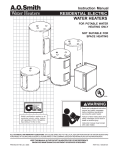
Instruction Manual
RESIDENTIAL ELECTRIC
2.5 GALLON 120 VOLT
WATER HEATER
FOR POTABLE WATER
HEATING ONLY
NOT SUITABLE FOR
SPACE HEATING
LISTED
ALL TECHNICAL AND WARRANTY QUESTIONS: SHOULD BE DIRECTED TO THE LOCAL DEALER FROM WHOM THE WATER HEATER WAS
PURCHASED. IF YOU ARE UNSUCCESSFUL, PLEASE WRITE TO THE COMPANY LISTED ON THE RATING PLATE ON THE WATER HEATER.
Keep this manual in the pocket on heater for future reference
when ever maintenance adjustment or service is required.
PRINTED 0707185834-000
SAFE INSTALLATION, USE AND SERVICE
Your safety and the safety of others is extremely important in the installation, use, and servicing of this water heater.
Many safety-related messages and instructions have been provided in this manual and on your own water heater to warn you
and others of a potential injury hazard. Read and obey all safety messages and instructions throughout this manual. It is very
important that the meaning of each safety message is understood by you and others who install, use, or service this water
heater.
This is the safety alert symbol. It is used to alert you
to potential personal injury hazards. Obey all safety
messages that follow this symbol to avoid possible
injury or death.
DANGER
DANGER indicates an imminently hazardous
situation which, if not avoided, could result
in death or injury.
WARNING
WARNING indicates a potentially hazardous
situation which, if not avoided, could result
in death or injury.
CAUTION
CAUTION
CAUTION indicates a potentially hazardous
situation which, if not avoided, may result
in minor or moderate injury.
CAUTION used without the safety alert
symbol indicates a potentially hazardous
situation which, if not avoided, could result
in property damage.
All safety messages will generally tell you about the type of hazard, what can happen if you do not follow the safety message,
and how to avoid the risk of injury.
The California Safe Drinking Water and Toxic Enforcement Act requires the Governor of California to publish a list of substances
known to the State of California to cause cancer, birth defects, or other reproductive harm, and requires businesses to warn of
potential exposure to such substances.
This product contains a chemical known to the State of California to cause cancer, birth defects, or other reproductive harm. This
appliance can cause low level exposure to some of the substances listed, including formaldehyde.
IMPORTANT DEFINITIONS
• Qualified Installer: A qualified installer must have ability equivalent to a licensed tradesman in the fields of plumbing and electrical
installation of these appliances. This would include a thorough understanding of the requirements of the National Electrical Code and
applicable local electrical and plumbing codes (and tools necessary to confirm proper installation and operation of the water heater) as
they relate to the installation of electric water heaters. The qualified installer must have a thorough understanding of the water heater
Instruction Manual.
• Service Agency: A service agency also must have ability equivalent to a licensed tradesman in the fields of plumbing and electrical
installation of these appliances. This would include a thorough understanding of the requirements of the National Electrical Code and
applicable local electrical and plumbing codes (and tools necessary to confirm proper installation and operation of the water heater) as
they relate to the installation of electric water heaters. The service agency must have a thorough understanding of the water heater
Instruction Manual.
GENERAL SAFETY
INTRODUCTION
Thank You for purchasing this water heater. Properly installed and
maintained, it should give you years of trouble free service.
2. The installation must conform with these instructions and the
local code authority having jurisdiction and the requirements of
the power company. In the absence of local code requirements
follow NFPA-70, the National Electrical Code (current edition),
which may be ordered from: National Fire Protection Association,
1 Batterymarch Park, Quincy, MA 02269.
Abbreviations Found In This Instruction Manual:
• ANSI - American National Standards Institute
• ASME - American Society of Mechanical Engineers
• NEC - National Electrical Code
• NFPA - National Fire Protection Association
• UL - Underwriters Laboratories Inc.
3. If after reading this manual you have any questions or do not
understand any portion of the instructions, call the local utility or
the manufacturer whose name appears on the rating plate.
4. Carefully plan your intended placement of the water heater.
INSTALLATION OR SERVICE OF THIS WATER HEATER
REQUIRES ABILITY EQUIVALENT TO THAT OF A LICENSED
TRADESMAN IN THE FIELD INVOLVED. PLUMBING
AND ELECTRICAL WORK ARE REQUIRED.
Preparing for the Installation
1. Read the “General Safety” section of this manual first and then
the entire manual carefully. If you don’t follow the safety rules,
the water heater will not operate properly. It could cause DEATH,
SERIOUS BODILY INJURY, AND/OR PROPERTY DAMAGE.
Examine the location to ensure the water heater complies with the
“Facts to Consider About the Location” section in this manual.
5. For California installation this water heater must be braced,
anchored, or strapped to avoid falling or moving during an
earthquake. See instructions for correct installation procedures.
Instructions may be obtained from California Office of the State
Architect, 400 P Street, Sacramento, CA 95814.
This manual contains instructions for the installation, operation,
and maintenance of the electric water heater. It also contains
warnings throughout the manual that you must read and
understand. All warnings and all instructions are essential to the
proper operation of the water heater and your safety. READ THE
ENTIRE MANUAL BEFORE ATTEMPTING TO INSTALL OR
OPERATE THE WATER HEATER.
6. Massachusetts Code requires this water heater to be installed in
accordance with Massachusetts 248-CMR 2.00: State Plumbing
Code and 248-CMR 5.00.
TABLE OF CONTENTS
SAFE INSTALLATION, USE AND SERVICE................................................................................................................................................................ 2
GENERAL SAFETY...................................................................................................................................................................................................... 3
INTRODUCTION........................................................................................................................................................................................................... 4
Preparing for the Installation................................................................................................................................................................................. 4
TABLE OF CONTENTS................................................................................................................................................................................................. 4
TYPICAL INSTALLATION.............................................................................................................................................................................................. 5
MIXING VALVE USAGE................................................................................................................................................................................................ 5
LOCATING THE NEW WATER HEATER...................................................................................................................................................................... 6
Facts to Consider About Location......................................................................................................................................................................... 6
Insulation Blankets................................................................................................................................................................................................ 6
IMPORTANT SAFETY INSTRUCTIONS....................................................................................................................................................................... 6
INSTALLING THE NEW WATER HEATER................................................................................................................................................................... 7
Mounting................................................................................................................................................................................................................ 7
Water Piping....................................................................................................................................................................................................... 7-8
Water Piping Pressure Test................................................................................................................................................................................... 8
Temperature-Pressure Relief Valve.................................................................................................................................................................... 8-9
Filling the Water Heater......................................................................................................................................................................................... 9
WIRING DIAGRAM..................................................................................................................................................................................................... 10
WIRING........................................................................................................................................................................................................................11
TEMPERATURE REGULATION................................................................................................................................................................................. 12
Temperature Adjustment..................................................................................................................................................................................... 12
FOR YOUR INFORMATION........................................................................................................................................................................................ 13
Thermal Expansion............................................................................................................................................................................................. 13
Strange Sounds................................................................................................................................................................................................... 13
Operational Conditions........................................................................................................................................................................................ 13
Water Odor.......................................................................................................................................................................................................... 13
“Air” in Hot Water Faucets................................................................................................................................................................................... 13
High Water Temperature Shut Off System.......................................................................................................................................................... 13
PERIODIC MAINTENANCE........................................................................................................................................................................................ 14
Anode Rod Inspection......................................................................................................................................................................................... 14
Temperature-Pressure Relief Valve Operation.................................................................................................................................................... 14
Draining............................................................................................................................................................................................................... 14
Removing Front Panel.................................................................................................................................................................................... 14-15
Thermostat Removal/Replacement..................................................................................................................................................................... 15
Element Cleaning/Replacement..................................................................................................................................................................... 15-16
High Limit Switch Removal and Replacement.................................................................................................................................................... 16
Service................................................................................................................................................................................................................ 16
LEAKAGE CHECKPOINTS......................................................................................................................................................................................... 17
TROUBLESHOOTING GUIDELINES.......................................................................................................................................................................... 18
REPAIR PARTS LIST.................................................................................................................................................................................................. 19
TYPICAL INSTALLATION
FIGURE 1.
MIXING VALVE USAGE
FIGURE 2.
HOTTER WATER CAN SCALD:
Water (Potable) Heating: All models are considered suitable for
water (potable) heating only.
Water heaters are intended to produce hot water. Water heated to a
temperature which will satisfy space heating, clothes washing, dish
washing, and other sanitizing needs can scald and permanently injure
you upon contact. Some people are more likely to be permanently
injured by hot water than others. These include the elderly, children,
the infirm, or physically/mentally disabled. If anyone using hot water in
your home fits into one of these groups or if there is a local code or state
law requiring a certain temperature water at the hot water tap, then you
must take special precautions. In addition to using the lowest possible
temperature setting that satisfies your hot water needs, a means such
as a mixing valve, should be used at the hot water taps used by these
people or at the water heater. Mixing valves are available from your local
plumbing contractor. Consult a Qualified Installer or Service Agency.
Follow mixing valve manufacturer’s instructions for installation of the
valves. Before changing the factory setting on the thermostat, read the
“Temperature Regulation” section in this manual.
LOCATING THE NEW WATER HEATER
pan should be installed under the water heater. Drain pans are
available from your local plumbing contractor. Such a drain
pan must have a minimum length and width of at least 2 inches
(51 mm) greater than the water heater dimensions and must
be piped to an adequate drain.
Facts to Consider About the Location
Water heater life depends upon water quality, water pressure,
water usage, water temperature, and the environment in which
the water heater is installed. Water heaters are sometimes
installed in locations where leakage may result in property
damage, even with the use of a drain pan piped to a drain.
However, unanticipated damage can be reduced or prevented
by a leak detector or water shut-off device used in conjunction with a piped drain pan. These devices are available from
some plumbing supply wholesalers and retailers, and detect
and react to leakage in various ways:
Carefully choose an indoor location for the new water heater,
because the placement is a very important consideration for the
safety of the occupants in the building and for the most economical
use of the appliance.
• Sensors mounted in the drain pan that trigger an alarm or turn off
the incoming water to the water heater when leakage is detected.
Whether replacing an old water heater or putting the water heater
in a new location, the following critical points must be observed:
• Sensors mounted in the drain pan that turn off the water supply to
the entire home when water is detected in the drain pan.
1. Select a location as close as practical or centralized to the point
of use. The water heater should be located in an area not subject
to freezing temperatures.
• Water supply shut-off devices that activate based on the
water pressure differential between the cold water and hot
water pipes connected to the water heater.
2. Selected location must provide adequate clearances for removing
the front cover in order to service parts such as the thermostat,
element, temperature sensor, anode, and high limit reset. Adequate
clearance for servicing this appliance should be considered before
installation, such as operating the relief valve, etc.
INSULATION BLANKETS
Insulation blankets are available to the general public for external
use on electric water heaters but are not necessary with this product.
The purpose of an insulation blanket is to reduce the standby heat
loss encountered with storage tank heaters.
3. The water heater should be located so it is not subject to physical
damage by moving vehicles or area flooding.
4. The selected wall or cabinet must be capable of supporting at
least two times the weight of the water heater when filled with
water (77 lbs).
Should you choose to apply an insulation blanket to this heater,
you should follow these instructions below. Failure to follow these
instructions can result in fire, serious personal injury, or death.
5. The water heater must be installed in a vertical position with water
inlet and outlet connections facing upwards and easily accessible.
• Do not cover the temperature and pressure relief (T & P) valve
with an insulation blanket.
Installation of the water heater must be accomplished in such
a manner that if the tank or any connections should leak, the
flow will not cause damage to the structure. For this reason, it
is not advisable to install the water heater in an attic or upper
floor. When such locations cannot be avoided, a suitable drain
• Do not cover the instruction manual. Keep it on the side of the
water heater or nearby for future reference.
• Do obtain new warning and instruction labels for placement on
the blanket directly over the existing labels.
important safety instructions
2. This water heater must be grounded. Connect only to properly
grounded outlet. See GROUNDING INSTRUCTIONS found in the
WIRING section of this manual.
3. Install or locate this water heater only in accordance with the
provided installation instructions.
4. Use this water heater for its intended use as described in this
manual.
5. Do not use an extension cord set with this water heater. If no
receptacle is available adjacent to the water heater, contact a
qualified electrician to have one properly installed.
6. As with any appliance, close supervision is necessary when used
by children.
7. Do not operate this water heater if it has a damaged cord or plug, if
it is not working properly, or if it has been damaged or dropped.
8. This water heater should be serviced only by qualified service
personnel. Contact nearest authorized service facility for
examination, repair, or adjustment.
1. READ ALL INSTRUCTIONS BEFORE USING THIS WATER HEATER.
INSTALLING THE NEW WATER HEATER
MOUNTING
water to a maximum depth of 2-1/2 inches and be 2 inches wider
than the unit. The pan must also be piped to an adequate drain.
See Figure 3B.
MOUNTING - DRYWALL (HOLLOW WALL)
1. The selected wall or cabinet must be capable of supporting double
the weight of the unit when completely full of water (77 Ibs).
2. The installation area must provide adequate clearances for
removal of the front panel and servicing the unit.
3. Locate the wall studs in the area where the unit is to be
mounted.
4. Cut two sections of 1/2 inch plywood or equivalent material 3
inches in height. The length of each section should be sufficient
to span the width of the wall studs. See Figure 3A.
5. Use appropriately sized nails or wood screws to attach the two
wall supports to the wall as show in Figure 3A.
6. Drill two 13/32 inch holes in the upper wall support NOTE: The
holes must be level.
7. Insert the hollow wall anchors into the drilled holes. Place the
wall bracket over the anchors and screw the two phillips head
screws down tight against the bracket.
FIGURE 3B.
Water Piping
MOUNTING - MASONRY WALL (SOLID WALL)
1. The selected wall or cabinet must be capable of supporting double
the weight of the unit when completely full of water (77 Ibs).
2. The installation area must provide adequate clearances for
removal of the front panel and servicing the unit.
3. Drill two 13/32 inch holes in the masonry wall. NOTE: The
holes must be level and at least 3-1/2 inches deep.
4. Insert the masonry wall anchors into the drilled holes. Place
the wall bracket over the anchors and screw the two phillips
head screws tight against the bracket.
HOTTER WATER CAN SCALD:
Water heaters are intended to produce hot water. Water heated to
a temperature which will satisfy space heating, clothes washing,
dish washing, cleaning and other sanitizing needs can scald and
permanently injure you upon contact. Some people are more likely to
be permanently injured by hot water than others. These include the
elderly, children, the infirm, or physically/mentally disabled. If anyone
using hot water in your home fits into one of these groups or if there
is a local code or state law requiring a certain temperature water at
the hot water tap, then you must take special precautions. In addition
to using the lowest possible temperature setting that satisfies your
hot water needs, a means such as a mixing valve should be used at
the hot water taps used by these people or at the water heater.
Valves for reducing point of use temperature by mixing cold and
hot water are also available.
FIGURE 3A.
MOUNTING - FLOOR
1. The floor selected must be capable of supporting double the
weight of the unit when completely full of water (77 Ibs).
2. The installation area must provide adequate clearances for
removal of the front panel and servicing the unit.
3. Place a suitable drain pan under the unit. The pan must limit the
Consult a Qualified Installer or Service Agency. Follow manufacturer’s
instructions for installation of the valves. Before changing the factory
setting on the thermostat, read the “Temperature Regulation” section
in this manual.
This water heater shall not be connected to any heating
systems or component(s) used with a non-potable water heating
appliance.
Toxic chemicals, such as those used for boiler treatment shall
not be introduced into this system.
Water supply systems may, because of such events as
high line pressure, frequent cut-offs, the effects of water
hammer among others, have installed devices such
as pressure reducing valves, check valves, back flow
preventers, etc. to control these types of problems. When
these devices are not equipped with an internal by-pass,
and no other measures are taken, the devices cause the
water system to be closed. As water is heated, it expands
(thermal expansion) and closed systems do not allow for
the expansion of heated water.
FIGURE 4.
WATER PIPING PRESSURE TEST
This section is only for the manufacturer installing the
water heater when the installation is to comply with H.U.D.
Standards.
When testing the water ways, H.U.D. Standards state:
“Water distribution system: All water piping in the water
distribution system shall be subjected to a pressure test.
The test shall be made by subjecting the system to air or
water at 100 psi for 15 minutes without loss of pressure.
When air pressure is used, the water heater shall not
be connected during the test.”
The water within the water heater tank expands as it is heated
and increases the pressure of the water system. If the relieving
point of the water heater’s temperature-pressure relief valve
is reached, the valve will relieve the excess pressure. The
temperature-pressure relief valve is not intended for the
constant relief of thermal expansion. This is an unacceptable
condition and must be corrected.
It is recommended that any devices installed which could create
a closed system have a by-pass and/or the system have an
expansion tank or device to relieve the pressure built by thermal
expansion in the water system. Expansion tanks are available
for ordering through a local plumbing contractor. Contact the
local water supplier and/or a service agency for assistance in
controlling these situations.
NOTE: To protect against untimely corrosion of hot and
cold water fittings, it is strongly recommended that dielectric unions or couplings be installed on this water
heater when connected to copper pipe.
Figure 4 shows the typical attachment of the water piping
to the water heater. The water heater is equipped with 1/2
inch NPT water connections.
Temperature- Pressure Relief Valve
NOTE: If using copper tubing, solder tubing to an adapter
before attaching the adapter to the cold water inlet
connection. Do not solder the cold water supply line directly
to the cold water inlet, it will harm the dip tube and damage
the tank.
This heater is provided with a properly certified combination
temperature - pressure relief valve by the manufacturer.
The valve is certified by a nationally recognized testing laboratory
that maintains periodic inspection of production of listed
equipment of materials as meeting the requirements for Relief
Valves for Hot Water Supply Systems, ANSI Z21.22 • CSA 4.4,
and the code requirements of ASME.
If replaced, the valve must meet the requirements of local codes,
but not less than a combination temperature and pressure relief
valve certified as indicated in the above paragraph.
The valve must be marked with a maximum set pressure not to
exceed the marked hydrostatic working pressure of the water heater
(150 psi = 1,035 kPa) and a discharge capacity not less than the
water heater input rate as shown on the model rating plate.
The temperature-pressure relief valve must be manually operated
at least once a year. Caution should be taken to ensure that (1) no
one is in front of or around the outlet of the temperature-pressure
relief valve discharge line, and (2) the water manually discharged
will not cause any bodily injury or property damage because the
water may be extremely hot.
For safe operation of the water heater, the relief valve must
not be removed from its designated opening nor plugged.
The temperature-pressure relief valve must be installed directly
into the fitting of the water heater designed for the relief valve.
Provide tubing so that any discharge will exit only within 6 inches
(153 mm) above an adequate drain, or external to the building
or structure. Be certain that no contact is made with any live
electrical part. The discharge opening must not be blocked or
reduced in size under any circumstances. Excessive length,
over 30 feet (9.14 m), or use of more than four elbows can cause
restriction and reduce the discharge capacity of the valve.
If after manually operating the valve, it fails to completely
reset and continues to release water, immediately close
the cold water inlet to the water heater, follow the draining
instructions, and replace the temperature-pressure relief valve
with a new one.
Filling the Water Heater
No valve or other obstruction is to be placed between the relief valve
and the tank. Do not connect tubing directly to discharge drain
unless a 6 inch air gap is provided. The relief valve must be allowed
to discharge water in sufficient quantities, should circumstances
demand, to prevent bodily injury, hazard to life, or property damage.
If the discharge pipe is not connected to a drain or other suitable
means, the water flow may cause property damage.
Never use this water heater unless it is completely full of
water. To prevent damage to the tank and heating element,
the tank must be filled with water. Water must flow from
the hot water faucet before turning “ON” electrical supply
to the water heater. The manufacturer will not warrant any
elements damaged by failure to follow instructions.
To fill the water heater with water:
The Discharge Pipe:
1. Open the cold water supply valve to the water heater.
NOTE: The cold water supply valve must be left open
when the water heater is in use.
• Shall not be smaller in size than the outlet pipe size of the valve,
or have any reducing couplings or other restrictions.
2. To ensure complete filling of the tank, allow air to exit
by opening the nearest hot water faucet. Allow water
to run until a constant flow is obtained. This will let air
out of the water heater and the piping.
• Shall not be plugged or blocked.
• Shall be of material listed for hot water distribution.
• Shall be installed so as to allow complete drainage of both the
temperature-pressure relief valve, and the discharge pipe.
3. Check all water piping and connections for leaks. Repair
as needed.
• Shall terminate at an adequate drain or external to the building
or structure.
4. Never alter or modify the certified construction of the
water heater or its components, or bypass any safety
features. Doing so voids all warranties.
• Shall not have any shut-off valve between the relief valve and
tank nor in the discharge pipe.
WIRING DIAGRAM
FIGURE 5.
10
WIRING
You must provide all wiring of the proper size outside of the water
heater. You must obey the local codes and the electric company
requirements when you install this wiring.
This water heater is supplied with a flexible, grounded power cord
and connects to a standard three-wire 120 volt 60Hz, grounded
type outlet. If an outlet is not within reach of the power cord,
contact a local electrician/electrical contractor or the local electric
utility to have a properly sized circuit (including outlet, wiring and
breaker) installed. NOTE: Check the water heater’s data plate
for power requirements.
If you are not familiar with the electric codes and practices, or
if you have any doubt, even the slightest doubt, in your ability
to connect the wiring to this water heater, obtain the service of
a competent electrician. Contact a local electrical contractor
and/or the local electric utility.
Never use the water heater unless it is completely full of water.
To prevent damage to the tank and the heating element, the tank
must be filled with water. Water must flow from the hot water
faucet before turning on the power.
WATER HEATERS EQUIPPED FOR ONE VOLTAGE ONLY:
This water heater is equipped for one type voltage only. Check
the rating plate near the bottom access panel for the correct
voltage. DO NOT use this water heater with any voltage other
than the one shown on the model rating plate. Failure to use the
correct voltage can cause problems which can result in DEATH,
SERIOUS BODILY INJURY, OR PROPERTY DAMAGE. If you
have any questions or doubts consult your electric company.
If wiring from your fuse box or circuit breaker box was aluminum
for your old water heater, replace it with copper wire. If you wish
to reuse the existing aluminum wire, have the connection at the
water heater made by a competent electrician. Contact a local
electrical contractor and/or the local electric utility.
11
TEMPERATURE REGULATION
TEMPERATURE ADJUSTMENT
To change the temperature setting:
The white knob on the front of the water heater is the temperature
control. When the “OFF” mark is aligned with the raised indicator
arrow, the water heater is off. Turn the knob clockwise to increase the
temperature, and counterclockwise to decrease the temperature. The
knob is marked with circular indentations of increasing size. The larger
the indentation, the higher the temperature setting. See Figure 6. The
temperature range of this water heater is 68°F at the lowest setting
and 150°F at the maximum setting. This water heater is shipped in the
“OFF” position. Adjust the dial to the desired temperature.
HOTTER WATER CAN SCALD: Water heaters are intended
to produce hot water. Water heated to a temperature
which will satisfy space heating, clothes washing, dish
washing, and other sanitizing needs can scald and
permanently injure you upon contact. Some people are
more likely to be permanently injured by hot water than
others. These include the elderly, children, the infirm, or
physically/mentally disabled. If anyone using hot water in
your home fits into one of these groups or if there is a
local code or state law requiring a certain temperature
water at the hot water tap, then you must take special
precautions. In addition to using the lowest possible
temperature setting that satisfies your hot water needs,
a means such as a mixing valve, should be used at
the hot water taps used by these people or at the
water heater. Mixing valves are available from your local
plumbing contractor. Follow manufacturer’s instructions
for installation of the valves. Before changing the factory
setting on the thermostat, see Figure 6.
Never allow small children to use a hot water tap or to draw
their own bath water. Never leave a child or handicapped
person unattended in a bathtub or shower.
It is recommended that lower water temperatures be used
to avoid the risk of scalding. It is further recommended,
in all cases, that the water temperature thermostat be
set for the lowest temperature which satisfies your hot
water needs. This will also provide the most energy
efficient operation of the water heater.
TEMPERATURE SETTINGS
It is recommended that the dial be set lower whenever possible.
KEEPING THE THERMOSTAT SETTING AT 120°F (49°C)
OR LOWER WILL REDUCE THE RISK OF SCALDS.
Figure 6 shows the approximate time-to-burn relationship for
normal adult skin.
Temperature
Setting
Time to Produce 2nd & 3rd
Degree Burns on Adult Skin
150°F (66°C)
About 1-1/2 seconds
140°F (60°C)
Less than 5 seconds
130°F (54°C)
About 30 seconds
120°F (49°C) More than 5 minutes
FIGURE 6.
12
FOR YOUR INFORMATION
THERMAL EXPANSION
“AIR” IN HOT WATER FAUCETS
Water supply systems may, because of such events as high line
pressure, frequent cut-offs, the effects of water hammer among others,
have installed devices such as pressure reducing valves, check valves,
back flow preventers, etc. to control these types of problems. When
these devices are not equipped with an internal by-pass, and no other
measures are taken, the devices cause the water system to be closed.
As water is heated, it expands (thermal expansion) and closed systems
do not allow for the expansion of heated water.
HYDROGEN GAS: Hydrogen gas can be produced in a hot water
system that has not been used for a long period of time (generally
two weeks or more). Hydrogen gas is extremely flammable and
explosive. To prevent the possibility of injury under these conditions,
we recommend the hot water faucet, located farthest away be opened
for several minutes before any electrical appliances which are
connected to the hot water system are used (such as a dishwasher
or washing machine). If hydrogen gas is present, there will probably
be an unusual sound similar to air escaping through the pipe as the
hot water faucet is opened. There must be no smoking or open
flame near the faucet at the time it is open.
The water within the water heater tank expands as it is heated and
increases the pressure of the water system. If the relieving point of
the water heater’s temperature-pressure relief valve is reached, the
valve will relieve the excess pressure. The temperature-pressure
relief valve is not intended for the constant relief of thermal
expansion. This is an unacceptable condition and must be corrected.
It is recommended that any devices installed which could create a
closed system have a by-pass and/or the system have an expansion
tank or device to relieve the pressure built by thermal expansion in
the water system. Expansion tanks are available for ordering through
a local plumbing contractor. Contact the local water heater supplier
or service agency for assistance in controlling these situations.
HIGH WATER TEMPERATURE SHUT OFF SYSTEM
A non-adjustable high temperature limit control operates before
steam temperatures are reached. The high limit switch must be reset
manually when it operates. BECAUSE THE HIGH LIMIT OPERATES
ONLY WHEN ABNORMALLY HIGH WATER TEMPERATURES
ARE PRESENT, IT IS IMPORTANT THAT A QUALIFIED
SERVICE AGENT BE CONTACTED TO DETERMINE
THE REASON FOR OPERATION BEFORE RESETTING .
STRANGE SOUNDS
Possible noises due to expansion and contraction of some metal
parts during periods of heat-up and cool-down do not necessarily
represent harmful or dangerous conditions.
Operational Conditions
Water odor
In each water heater there is installed at least one anode rod (see
parts sections) for corrosion protection of the tank. Certain water
conditions will cause a reaction between this rod and the water.
The most common complaint associated with the anode rod is one
of a “rotten egg smell” in the hot water. This odor is derived from
hydrogen sulfide gas dissolved in the water. The smell is the result
of four factors which must all be present for the odor to develop:
A. A concentration of sulfate in the supply water.
B. Little or no dissolved oxygen in the water.
C. A sulfate reducing bacteria which has accumulated within the
water heater (this harmless bacteria is nontoxic to humans).
D. An excess of active hydrogen in the tank. This is caused by the
corrosion protective action of the anode.
• Turn off and unplug the water heater. Do not attempt to reset
thermostat with power on.
• Remove the front panel, see “Removing Front Panel” in the
Periodic Maintenance section.
Smelly water may be eliminated or reduced in some water heater
models by replacing the anode(s) with one of less active material,
and then chlorinating the water heater tank and all hot water lines.
Contact the local water heater supplier or service agency for further
information concerning an Anode Replacement Kit and this chlorination
treatment. If the smelly water persists after the anode replacement and
chlorination treatment, we can only suggest that chlorination or aeration
of the water supply be considered to eliminate the water problem.
• Remove the insulation to expose the reset button.
• Reset the high limit by pushing in the red button.
• Replace the insulation so that it completely covers the thermostat
and element.
• Replace the front panel.
Do not remove the anode leaving the tank unprotected. By doing
so, all warranty on the water heater tank is voided.
• Plug in and turn on the water heater.
13
PERIODIC MAINTENANCE
ANODE ROD INSPECTION
not cause any property damage, as the water may be extremely hot,
see Figure 7.
The anode rod is used to protect the tank from corrosion. Most hot
water tanks are equipped with an anode rod. The submerged rod
sacrifices itself to protect the tank. Instead of corroding the tank, water
ions attack and eat away the anode rod. This does not affect the
water’s taste or color. The rod must be maintained to keep the tank
in operating condition.
FIGURE 7.
If after manually operating the valve, it fails to completely reset and
continues to release water, immediately close the cold water inlet
to the water heater, follow the draining instructions, and replace the
temperature-pressure relief valve with a new one.
NOTE: The use of a water softener may decrease the life of the water
heater tank.
If the temperature-pressure relief valve on the appliance weeps
or discharges periodically, this may be due to thermal expansion.
You may have a check valve installed in the water line or a water
meter with a check valve. Consult your local water supplier or
service agency for further information. Do not plug or remove the
temperature-pressure relief valve.
Anode deterioration depends on water conductivity, not
necessarily water condition. A corroded or pitted anode rod
indicates high water conductivity and should be checked and/or
replaced more often than an anode rod that appears to be
intact. Replacement of a depleted anode rod can extend the
life of your water heater. Inspection should be conducted by a
qualified technician, and at a minimum should be checked every
three years. The anode rod in this unit is attached to the element
flange. For removal instructions, see “Element Cleaning /
Replacement.”
Draining
Typical (but not all) signs of a depleted anode rod are as
follows:
• The majority of the rods diameter is less than 3/8”
• Significant sections of the support wire (approximately 1/3 or more
of the anode rod’s length) are visible.
If the anode rod shows signs of either or both it should be replaced.
NOTE: Whether re-installing or replacing the anode rod, check
for any leaks and immediately correct if found.
The water heater should be drained if being shut down during
freezing temperatures. Also periodic draining and cleaning of
sediment from the tank may be necessary.
Temperature-Pressure Relief Valve Operation
1. Turn off and unplug the water heater from the electrical outlet.
2. CLOSE the cold water inlet valve to the water heater.
3. OPEN a nearby hot water faucet and leave open to allow for
draining.
4. Disconnect water connections. Remove unit from wall. UNIT WILL
BE HEAVY. Turn unit upside down and drain unit into a suitable
drain or receptacle.
removing the front panel
The temperature-pressure relief valve must be manually operated
at least once a year.
1. Turn off and unplug the water heater from the electrical outlet
and follow “DRAINING INSTRUCTIONS.”
When checking the temperature-pressure relief valve operation, make
sure that (1) no one is in front of or around the outlet of the temperaturepressure relief valve discharge line, and (2) that the water discharge will
2. Remove the temperature knob by pulling straight out.
14
3. Using a Philips screwdriver, unscrew the bottom screw securing
the outer door, see Figure 8.
REPLACEMENT
1. Place the new thermostat against the front panel and secure
it with the two screws.
4. Lift up and remove front panel.
2. Reattach the wires at the spade connections, taking care to
place them in their original locations. Be sure to push the
connector completely onto the spade terminals.
3. Secure the temperature sensor to the tank by tightening the
nuts. Be sure the sensor is firmly in contact with the tank
surface.
4. Replace the insulation block and the front panel.
ELEMENT CLEANING / REPLACEMENT
FIGURE 8.
Thermostat REMOVAL / REPLACEMENT
To remove the element from the tank in order to clean or replace it:
1. Turn off and unplug the water heater from the electrical outlet
and follow “DRAINING INSTRUCTIONS.”
2. Remove the front panel, see the “REMOVING THE FRONT
PANEL” section in this manual. Remove the insulation pad.
REMOVAL
3. Remove the two screws from the mounting bracket, see Figure
10, being careful not to drop the screws into the unit, as they will
be difficult to retrieve. Remove bracket and set screws aside.
1. Turn off and unplug the water heater from the electrical outlet.
2. Remove the front panel, see the “REMOVING THE FRONT
PANEL” section in this manual. Remove the insulation pad.
4. Remove the two spade connectors from the element.
3. Using a 7mm wrench, loosen the nuts securing the high limit switch
to the tank enough to rotate the switch 90° counterclockwise and
slide it out from beneath the bracket. It is not necessary to remove
the nuts completely.
5. Using a 10mm wrench, remove the four nuts around the element
flange. Set nuts and lockwashers aside.
6. Lift element up to clear the four mounting bolts, rotate 15° clockwise,
and lift out.
4. Remove the 3 wires (white, brown, and green/yellow) from the
thermostat at the spade connections, carefully taking note of the
original location of each wire.
7. Discard the old gasket and clean the area around the element
opening. Remove any sediment from or around the element opening
and inside the tank.
5. Unscrew the 2 screws securing the thermostat to the front panel
and remove thermostat.
8. If you are cleaning the element you have removed, do so by
scraping or soaking in vinegar or a deliming solution.
NOTE: Replacement elements must (1) be the same voltage
and (2) no greater wattage than listed on the model rating plate
affixed to the water heater.
9. A new gasket must be used in all cases to prevent a possible
water leak. Place new element gasket in the element opening
over the four element bolts, orienting the gasket bulge facing
water side.
10.Insert the curved part of the element, rotate 20° clockwise, and
continue to insert the element, being sure that the four bolts fit into
the element flange.
11.Replace the four lockwashers and 10mm nuts. Tighten until snug.
DO NOT OVERTIGHTEN.
12.Place unit back on wall mounting bracket hooks. Reconnect the
FIGURE 9.
15
water inlet and outlet, open the nearest hot water tap and follow
filling instructions.
5. Follow instructions for replacing the element in “ELEMENT
CLEANING/REPLACEMENT.”
High Limit Switch Removal and replacement
1. Turn off and unplug the heater from the electrical outlet.
2. Remove the front panel, see the “REMOVING THE FRONT
PANEL” section in this manual. Remove the insulation pad.
Remove personnel barrier.
3. Remove the four wires connected to the switch, taking care
to note the original placement of each wire.
Never use this water heater unless it is completely full of water. To
prevent damage to the tank and heating element, the tank must be
filled with water. Water must flow from the hot water faucet before
turning “ON” power. The manufacturer will not warrant any elements
damaged by failure to follow instructions.
4. Using a 7mm wrench, remove the nuts securing the high
limit switch to the tank enough to rotate the switch 90°
counterclockwise and slide it out from beneath the bracket.
It is not necessary to remove the nuts completely.
15.Check element for water leaks. If leakage occurs, tighten element.
If necessary drain tank before repeating Steps 7 and 8, remove
element and reposition gasket. Then repeat Steps 10 through 15.
5. Place the new switch beneath the bracket and rotate it 90°
clockwise.
16.Replace the two spade connectors on element into their original
positions.
NOTE: The taller spade terminal will be on the right side.
17.Replace the mounting bracket with the center rise facing outward
and the screw hole up, see Figure 10.
18.Replace the insulation and front panel, lining up the three tabs at
the top with the slots in the casing.
19.Replace the retaining screw and the temperature knob.
20.Plug heater into electrical outlet.
figure 11.
6. Replace and tighten the nuts so the high limit switch is firmly
in contact with the tank surface.
7. Replace the four wires, taking care that they are replaced
into their original positions and tighten screws.
8. Replace personnel barrier; replace insulation block and the
front panel.
Service
If a condition persists or you are uncertain about the operation
of the water heater contact a service agency.
FIGURE 10.
Use this guide to check a “Leaking” water heater. Many
suspected “Leakers” are not leaking tanks. Often the source of
the water can be found and corrected.
TO REMOVE AND REPLACE ANODE:
1. Follow steps 1-8 of the Element Cleaning/Replacement section.
2. Using a 7mm wrench, remove the nut securing the anode.
If you are not thoroughly familiar with your water heater and
safety practices, contact a qualified installer to check the water
heater.
3. Unscrew and remove anode.
4. Screw in the new anode and secure with the retaining nut.
16
LEAKAGE CHECKPOINTS
Read this manual first. Make sure the electrical power supply has
been turned “OFF” before checking the tank for leakage.
*A. Condensation and dripping may be seen on pipes if the water
temperature is low in humid weather or pipe connections may
be leaking.
B. Small amounts of water from temperature-pressure relief valve
may be due to thermal expansion or high water pressure in your
area. If the valve is not piped to an open drain the released
water could be mistaken for a leaking heater, see “Thermal
Expansion” section.
*C. The temperature-pressure relief valve may be leaking at the
tank fitting.
FIGURE 12.
D. Water on the side of the tank may be condensation due to the
panel or insulation not being in place.
*E. Water in the water heater bottom or on the floor may be from
condensation, loose connections, or the relief valve. DO NOT
replace the water heater until a full inspection of all possible
water sources is made and necessary corrective steps taken.
Leakage from other appliances, water lines, or ground seepage
should also be checked.
* To check where threaded portion enters tank, insert cotton
swab between jacket opening and fitting. If cotton is wet, follow
“Draining” instructions in the “Periodic Maintenance” section
and then remove fitting. Put pipe dope or teflon tape on the
threads and replace. Then follow “Filling the Water Heater”
instructions in the “Installing the New Water Heater” section.
Key No.Part Description
17
TROUBLESHOOTING GUIDELINES
These guidelines should be utilized by a qualified service agent.
ProblemPossible Cause(s)Corrective Action
WATER LEAKS
(See Leakage Checkpoints in this manual)
Improperly sealed, hot or cold supply connection,
relief valve or drain valve.
Leakage from other appliances or water lines.
Tighten threaded connections.
No power to heater.
Turn on electrical switch. Check for blown
fuses or tripped breaker.
High Temperature Limit Switch open.
Reset. Check for source of trouble and correct.
Non-functioning thermostat.
Replace thermostat.
Non-functioning thermostat.
Replace thermostat.
Improper calibration.
Replace thermostat.
Thermostat set too low.
Set thermostat to desired temperature.
Sediment or lime in tank.
Drain. Determine if water treatment is needed.
Heater too small for job.
Install adequate water heater.
Wrong piping connections.
Correct piping.
Leaking faucets.
Repair faucets.
Wasted hot water.
Review and reduce hot water consumption.
Long runs of exposed pipe.
Insulate piping.
Hot water piping on outside wall.
Insulate piping.
Improper Calibration.
Replace thermostat.
Thermostat set too high.
Set thermostat to desired setting.
Sediment or lime in tank.
Drain. Flush-Provide water treatment if needed.
Heater too small for job.
Install adequate heater.
Wrong piping connections.
Correct piping.
Leaking faucets.
Repair faucets.
Wasted hot water.
Review and reduce hot water consumption.
Long runs of exposed piping.
Insulate piping.
Hot water piping in exposed wall.
Insulate piping.
SLOW HOT WATER RECOVERY
Non-functioning element.
Replace element.
DRIP FROM RELIEF VALVE
Excessive water pressure.
Use Pressure Reducing Valve and Pressure
Relief Valve.
Closed system.
See “Thermal Expansion” in the For Your Information section.
Non-functioning thermostats.
Replace thermostats.
Improper calibration.
Replace thermostats.
Sulfides in the water.
See “Operational Conditions” in the For Your
Information section.
Scale accumulation on elements.
Contact dealer to clean or replace elements.
NO HOT WATER
INSUFFICIENT HOT WATER
HIGH OPERATION COSTS
THERMOSTAT DOES NOT SHUT OFF
WATER ODOR
WATER HEATER SOUNDS
18
Inspect other appliances near water heater.
REPAIR PARTS LIST
Now that you have purchased this water heater, should a need
1Element Gasket
2Anode Rod
3Element Assembly with Gasket, Anode & Fasteners
4High Limit with Personnel Barrier
5-6Temperature Sensor and Thermostat
7Mounting Bracket
8Front Panel
9Temperature Control Knob
10Heat Traps
11Dip Tube
12Temperature-Pressure Relief Valve
ever exist for repair parts or service, simply contact the company
it was purchased from or the manufacturer listed on the rating
plate on the water heater.
Be sure to provide all pertinent facts when you call or visit.
Selling prices will be furnished on request or parts will
be shipped at prevailing prices and you will be billed
accordingly.
The model number of your Water Heater will be found on the
rating plate located above or adjacent to outer door.
WHEN ORDERING REPAIR PARTS, ALWAYS GIVE THE
FOLLOWING INFORMATION:
•
•
•
•
*13Element Bolts
14Personnel Barrier
*15Manual
* Not Illustrated.
MODEL NUMBER
SERIAL NUMBER
VOLTAGE AND ELEMENT WATTAGE
PART DESCRIPTION
THIS IS A REPAIR PARTS LIST, NOT A PACKING LIST.
figure 13.
19
RESIDENTIAL ELECTRIC WARRANTY
THIS WARRANTY IS APPLICABLE TO THE ORIGINAL
OWNER ONLY. In accordance with the warranty terms and
conditions specified below.
A. O. Smith Corporation (the warrantor) will furnish the
ORIGINAL OWNER, 1) a replacement A. O. Smith water
heater of equivalent size and current model if the glasslined
tank in this water heater leaks and, 2) a replacement part
for any component part which fails.
THE A. O. SMITH WATER HEATERS REPLACEMENT
MODEL OR PART WILL BE WARRANTED FOR ONLY THE
UNEXPIRED PORTION OF THE ORIGINAL WARRANTY.
The warranty period will be determined by the original date
of purchase of the water heater, or in the absence of a Bill
of Sale verifying said date, from the date of manufacture
indicated on rating plate affixed to this water heater. This
warranty is not transferrable and applies to models listed
below:
SeriesTankParts
ProMax® 6-Year Models
6-year
6-year
ECJ,
When the water heater has been used for other than single
family residential application;
1. The tank warranty shall be reduced to 1 year for 6 year
models.
2. The parts warranty shall be reduced to 1 year for all
models.
CONDITIONS AND EXCEPTIONS
This warranty shall apply only when the water heater is
installed and operated in accordance with 1) all local fire
codes and plumbing codes, ordinances and regulations,
2) the printed instructions provided with it, 3) good industry
practices, and 4) proper safety practices such as but not
limited to a properly sized drain pan if installed in an area
where leakage from the tank or its connections would result
in damage to the area adjacent to the heater. In addition, a
new temperature and pressure relief valve, certified by the
Canadian Gas Association must have been properly installed
and piped to the nearest drain.
20
This warranty shall apply only when the heater is:
•
•
•
•
•
•
•
•
•
•
•
•
•
•
•
owned by the original purchaser;
installed for indoor operation only;
used at temperatures not exceeding the maximum
calibrated setting of its thermostat;
used at water pressure not exceeding the working
pressure shown on the heater;
filled with potable water, free to circulate at all times
and with the tank free of damaging water sediment
or scale deposits;
used in a non-corrosive and non-contaminated
atmosphere;
used with factory approved anode(s) installed;
in its original installation location;
in the United States, its territories or possessions,
and Canada;
sized in accordance with proper sizing techniques
for residential water heaters;
bearing a rating plate which has not been altered,
defaced or removed except as required by the
warrantor;
used in an open system or in a closed system with
a properly sized and installed thermal expansion tank;
connected to the proper voltage or:
operated at the factory rated input;
installed with no attempted, nor actual modification
or alteration of the water heater’s design in any way,
including but not limited to, the attachment of noncompany approved appliances or equipment.
Any accident to the water heater or any part thereof
(including freezing, fire, floods, or lightning), any misuse,
abuse or alteration of it, any operation of it in a modified
form, any operation of the water heater on desalinated
(deionized) water, or any damage caused by attempts
to repair tank leaks or parts, will void this warranty. This
warranty does not cover water heaters replaced for
cosmetic reasons or for reasons of noise, taste, odor,
discolored and/or rusty water. This warranty does not
apply to water heaters used to heat pools, whirlpools or
hot tubs or used for space heating where its sizing does
not conform with specifications of the heating component
manufacturer.
This warranty gives you specific legal rights, and you may
have other rights which vary under the laws of each state. If
any provision of this warranty is prohibited or invalid under
applicable state law, that provision shall be ineffective to
the extent of the prohibition or invalidity
without invalidating the remainder of the affected provision
or the other provisions of this warranty.
Dealer replacements are made subject to in-warranty
validation by warrantor.
SERVICE AND LABOR RESPONSIBILITY
PROOF OF PURCHASE AND PROOF OF INSTALLATION
DATE ARE REQUIRED TO SUPPORT WARRANTY CLAIM
FROM ORIGINAL OWNER. THIS FORM DOES NOT
CONSTITUTE PROOF OF PURCHASE OR PROOF OF
INSTALLATION.
UNDER THIS LIMITED WARRANTY, THE WARRANTOR
WILL PROVIDE ONLY A REPLACEMENT WATER
HEATER OR PART THEREOF. THE OWNER IS
RESPONSIBLE FOR ALL OTHER COSTS. Such costs
may include but are not limited to:
a. Labor charges for service, removal, or reinstallation
of the water heater or part thereof.
b.
Shipping and delivery charges for forwarding the new
water heater or replacement part from the nearest
distributor and returning the claimed defective heater
or part to such distributor.
c.
All cost necessary or incidental for handling and
administrative charges, and for any materials and/or
permits required for installation of the replacement
heater or part.
LIMITATION ON IMPLIED WARRANTIES
Implied warranties, including any warranty of
merchantability imposed on the sale of this heater under
state law are limited to one year duration for the heater
or any of its parts. Some states do not allow limitations
on how long an implied warranty lasts, so the above
limitations may not apply to you.
CLAIM PROCEDURE
Any claim under this warranty should be initiated with
the dealer who sold the heater, or with any other dealer
handling the warrantor’s products. If this is not practical,
the owner should contact: A.O. Smith Corporation,
500 Tennessee Waltz Parkway, Ashland City, TN 37015.
Phone: 1.800.323.2636 or visit our website: www.
hotwater.com.
For Canadian customers contact: A.O. Smith Enterprises
LTD., P.O. Box 310, 768 Erie Street, Stratford, Ontario
N5A6T3 or phone: 1.800.265.8520
Replacement Parts may be ordered through authorized
servicers or distributors. Refer to your local Yellow Pages
for where to call or contact A.O. Smith Corporation,
500 Tennessee Waltz Parkway, Ashland City, TN 37015.
Phone: 1.800.433.2545 or visit our website at: www.
hotwater.com/parts.
The warrantor will only honor replacement with identical
or similar water heater or parts thereof which are
manufactured or distributed by the warrantor.
DISCLAIMERS
NO EXPRESSED WARRANTY HAS BEEN OR WILL BE
MADE IN BEHALF OF THE WARRANTOR WITH
RESPECT TO THE MERCHANTABILITY OF THE
HEATER OR THE INSTALLATION, OPERATION, REPAIR
OR REPLACEMENT OF THE HEATER OR PARTS.
THE WARRANTOR SHALL NOT BE RESPONSIBLE
FOR WATER DAMAGE, LOSS OF USE OF THE UNIT,
INCONVENIENCE, LOSS OR DAMAGE TO PERSONAL
PROPERTY, OR OTHER CONSEQUENTIAL DAMAGE.
THE WARRANTOR SHALL NOT BE LIABLE BY VIRTUE
OF THIS WARRANTY OR OTHERWISE FOR DAMAGE
TO ANY PERSONS OR PROPERTY, WHETHER DIRECT
OR INDIRECT, AND WHETHER ARISING IN CONTRACT
OR IN TORT.
Should governmental regulations or industry standards
prohibit the Manufacturer from furnishing a comparable
model replacement under this warranty, the Owner will
be furnished with the closest comparable water heater
meeting the then current governmental regulations and
industry standards. A supplementary fee may be assessed
to cover the additional cost associated with the changes
made to meet applicable regulations and standards.
IMPORTANT INFORMATION
Model Number_________________________________
Serial Number_________________________________
Installation Information
Date Installed _ _______________________________
Company’s Name ______________________________
Street or P.O. Box _ ____________________________
City, State, and Zip Code_________________________
Phone Number_________________________________
Plumber’s Name _______________________________
www.aosmithwaterheaters.com
21
NOTES:
____________________________________________________
____________________________________________________
____________________________________________________
____________________________________________________
____________________________________________________
____________________________________________________
____________________________________________________
____________________________________________________
____________________________________________________
____________________________________________________
____________________________________________________
____________________________________________________
____________________________________________________
____________________________________________________
____________________________________________________
____________________________________________________
____________________________________________________
____________________________________________________
____________________________________________________
____________________________________________________
____________________________________________________
____________________________________________________
____________________________________________________
____________________________________________________
____________________________________________________
____________________________________________________
____________________________________________________
____________________________________________________
____________________________________________________
____________________________________________________
____________________________________________________
____________________________________________________
22
NOTES:
____________________________________________________
____________________________________________________
____________________________________________________
____________________________________________________
____________________________________________________
____________________________________________________
____________________________________________________
____________________________________________________
____________________________________________________
____________________________________________________
____________________________________________________
____________________________________________________
____________________________________________________
____________________________________________________
____________________________________________________
____________________________________________________
____________________________________________________
____________________________________________________
____________________________________________________
____________________________________________________
____________________________________________________
____________________________________________________
____________________________________________________
____________________________________________________
____________________________________________________
____________________________________________________
____________________________________________________
____________________________________________________
____________________________________________________
____________________________________________________
____________________________________________________
____________________________________________________
23
www.aosmithwaterheaters.com
24