1
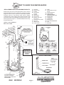
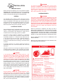
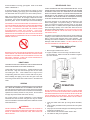
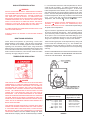
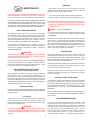
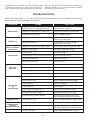
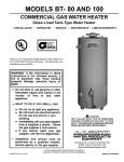
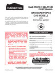
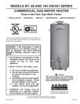
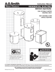
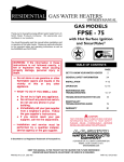
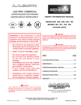
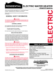
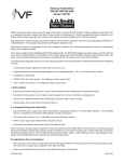
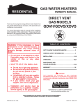
GAS WATER HEATER
OWNER'S MANUAL
GAS
RESIDENTIAL
Thank you for buying this energy efficient water heater from
A.O. Smith Water Products Company. We appreciate your
confidence in our products.
You should thoroughly read this manual before installation
and/or operation of this water heater. Please pay particular
attention to the important safety and operating instructions as
well as the WARNINGS and CAUTIONS.
TABLE OF CONTENTS
PAGE
GET TO KNOW YOUR WATER HEATER
2
GENERAL SAFETY INFORMATION
3
INSTALLATION
4 -6
OPERATION
6 -8
MAINTENANCE AND
TROUBLESHOOTING
8 -10
WARRANTY
11
CAUTION
TEXT PRINTED OR OUTLINED IN RED CONTAINS
INFORMATION RELATIVE TO YOUR SAFETY. PLEASE
READ THOROUGHLY BEFORE INSTALLING AND
USING THIS APPLIANCE.
A DIVISION OF A.O. SMITH CORPORATION
www.aosmithwaterheaters.com
KEEP THIS MANUAL IN THE POCKET ON HEATER FOR FUTURE REFERENCE
WHENEVER MAINTENANCE ADJUSTMENT OR SERVICE IS REQUIRED.
PRINTED IN U.S.A. 0104
1
PART NO. 184769-000
GET TO KNOW YOUR WATER HEATER
REPLACEMENT PARTS AND DELIMING PRODUCTS
(A)
(B)
(C)
(D)
Replacement parts and recommended delimer may be ordered
through authorized servicers or distributors. Refer to the Yellow
Pages for where to call or contact A.O. Smith Water Products
Company, 5621 W. 115th Street, Alsip, Illinois 60803,
1-800-433-2545. When ordering parts, provide complete model
and serial numbers (see rating plate), quantity and name of part
desired (as listed in Figure 1). Standards hardware items may
be purchased locally.
(E)
(F)
(G)
(H)
(J)
(K)
(L)
(M)
*INSTALL IN ACCORDANCE
WITH LOCAL CODES.
VENT PIPE
DRAFT HOOD
ANODE
HOT WATER
OUTLET
OUTLET
INSULATION
GAS SUPPLY
MANUAL GAS SHUT
OFF VALVE
GROUND JOINT UNION
DIRT LEG
INNER DOOR
OUTER DOOR
(N) UNION
O) INLET WATER SHUT OFF
VALVE
(P) COLD WATER INLET
(Q) INLET DIP TUBE
(R) TEMPERATURE AND
PRESSURE RELIEF VALVE
(S) RATING PLATE
(T) FLUE BAFFLE
(U) THERMOSTAT
(V) DRAIN VALVE
(W) PILOT AND MAIN BURNER
(X) FLUE
(Y) DRAIN PAN
(U) THERMOSTAT
CERTAIN MODELS ARE
EQUIPPED WITH SIDE
PLUMBING CONNECTIONS
FOR SPACE HEATING. THE
HOT AND COLD FITTING
ASSEMBLIES
(PART #900126-2).
(W) PILOT & MAIN BURNER
GAS MODELS
FIGURE 1
2
GENERAL SAFETY
INFORMATION
suspected, do not attempt to find the cause yourself. Go to a
neighbor's house, leaving your doors open to ventilate the house,
then call your gas supplier or service agent. Keep area clear
until a service call has been made.
EXTERNAL DAMAGE
At times you may not be able to smell an LP gas leak. One
cause is odor fade, which is a loss of the chemical odorant that
gives LP gas its distinctive smell. Another cause can be your
physical condition, such as having a cold or a diminishing sense
of smell with age. For these reasons, the use of a propane gas
detector is recommended.
The design of this gas-fired water heater complies with the
latest version of ANSIZ21.10.1/CSA4.1 or ANSIZ21.10.3/CSA4.3
as a automatic storage type water heater.
Do not operate the water heater until it has been fully checked
out by a qualified technician, if the water heater:
IF YOU EXPERIENCE AN OUT-OF-GAS SITUATION, DO NOT
TRY TO RELIGHT APPLIANCES YOURSELF. Ask your LP
delivery person to relight pilots for you. Only trained LP
professional should conduct the required safety checks in
accordance with industry standards.
• Has been exposed to fire or damage.
• Displays evidence of sooting.
• Produces steam or unusually hot water.
If the water heater has been flooded it must be replaced.
EXTENDED NON-USE PERIODS
CHEMICAL VAPOR CORROSION
WARNING
WARNING
HYDROGEN GAS CAN BE PRODUCED IN A HOT WATER
SYSTEM SERVED BY THIS HEATER THAT HAS NOT BEEN
USED FOR A LONG PERIOD OF TIME (GENERALLY TWO
WEEKS OR MORE). HYDROGEN GAS IS EXTREMELY
FLAMMABLE. To reduce the risk of injury under these conditions,
it is recommended that the hot water faucet be opened for several
minutes at the kitchen sink before using any electrical appliance
connected to the hot water system. If hydrogen is present, there
will probably be an unusual sound such as air escaping through
the pipe as the water begins to flow. THERE SHOULD BE NO
SMOKING OR OPEN FLAME NEAR THE FAUCET AT THE TIME
IT IS OPEN.
CORROSION OF THE FLUEWAYS AND VENT SYSTEM MAY
OCCUR IF AIR FOR COMBUSTION CONTAINS CERTAIN
CHEMICAL VAPORS. SUCH CORROSION MAY RESULT IN
FAILURE AND RISK OF ASPHYXIATION.
Spray can propellants, cleaning solvents, refrigerator and air
conditioning refrigerants, swimming pool chemicals, calcium
and sodium chloride (water softener salt), waxes, and process
chemicals are typical compounds which are potentially
corrosive.
Do not store products of this sort near the heater. Also, air
which is brought in contact with the heater should not contain
any of these chemicals. If necessary, uncontaminated air should
be obtained from remote or outside sources. Water heater
failure due to a corrosive atmosphere is not covered by the
limited warranty.
INSULATION BLANKETS
Insulation blankets available to the general public for external
use on gas water heaters are not necessary with A. O. Smith
products. The purpose of an insulation blanket is to reduce the
standby heat loss encountered with storage tank heaters. Your
A. O. Smith water heater meets or exceeds the National
Appliance Energy Conservation Act standards with respect to
insulation and standby loss requirements, making an insulation
blanket unnecessary.
IMPROPER COMBUSTION
WARNING
ATTIC AND/OR EXHAUST FANS OPERATING ON THE
PREMISES WITH A WATER HEATER CAN RESULT IN
CARBON MONOXIDE POISONING AND DEATH.
WARNING
OPERATION OF THESE FANS CAN PRODUCE A NEGATIVE
DRAFT IN THE AREA OF THE WATER HEATER
PREVENTING THE PRODUCTS OF COMBUSTION FROM
EXHAUSTING THROUGH THE CHIMNEY OR VENT PIPE.
Should you choose to apply an insulation blanket to this heater,
you should follow these instructions (See Figure 1 for
identification of components mentioned below). Failure to follow
these instructions can restrict the air flow required for proper
combustion, potentially resulting in fire, asphyxiation, serious
personal injury or death.
The venting of the water heater should be inspected by a
qualified service technician at the time of installation and
periodically thereafter to ensure a down-draft condition does
not exist.
• Do not apply insulation to the top of the water heater, as this
will interfere with safe operation of the draft hood.
DO NOT OBSTRUCT THE FLOW OF COMBUSTION AND
VENTILATING AIR. ADEQUATE AIR FOR COMBUSTION AND
VENTILATION MUST BE PROVIDED FOR SAFE OPERATION.
• Do not cover the outer door, thermostat or temperature &
pressure relief valve.
LIQUID PETROLEUM MODELS
• Do not allow insulation to come within 2" of the floor to
prevent blockage of combustion air flow to the burner.
Water heaters for propane or liquefied petroleum gas (LPG)
are different from natural gas models. A natural gas heater will
not function safely on LP gas and no attempt should be made to
convert a heater from natural gas to LP gas.
• Do not cover the instruction manual. Keep it on the side of
the water heater or nearby for future reference.
• Do obtain new warning and instruction labels from A.O.Smith
for placement on the blanket directly over the existing labels.
LP gas must be used with great caution. It is highly explosive
and heavier than air. It collects first in the low areas making its
odor difficult to detect at nose level. If LP gas is present or even
• Do inspect the insulation blanket frequently to make certain it
does not sag, thereby obstructing combustion air flow.
3
WARNING
INSTALLATION
For California installation this water heater must be braced,
anchored, or strapped to avoid falling or moving during an
earthquake. See instructions for correct installation procedures.
Instructions may be obtained from your local dealer, wholesaler,
public utilities or California's Office of the State Architect,
400 P Street, Sacramento, CA 95814.
REQUIRED ABILITY
INSTALLATION OR SERVICE OF THIS WATER HEATER
REQUIRES ABILITY EQUIVALENT TO THAT OF A LICENSED
TRADESMAN IN THE FIELD INVOLVED. PLUMBING, AIR
SUPPLY, VENTING AND GAS SUPPLY ARE REQUIRED.
AIR REQUIREMENTS
WARNING
GENERAL
FOR SAFE OPERATION PROVIDE ADEQUATE AIR FOR
COMBUSTION AND VENTILATION. AN INSUFFICIENT SUPPLY
OF AIR WILL CAUSE RECIRCULATION OF COMBUSTION
PRODUCTS RESULTING IN AIR CONTAMINATION THAT MAY
BE HAZARDOUS TO LIFE. SUCH A CONDITION OFTEN WILL
RESULT IN A YELLOW, LUMINOUS BURNER FLAME, CAUSING
CARBONING OR SOOTING OF THE COMBUSTION CHAMBER,
BURNERS, AND FLUE TUBES AND CREATES A RISK OF
ASPHYXIATION.
The installation must conform to these instructions and the
local code authority having jurisdiction. In the absence of local
codes, the installation must comply with the latest editions of
the National Fuel Gas Code, ANSI Z223.1/NFPA 54. The code is
available from the Canadian Standards Association,
8501 East Pleasant Valley Road, Cleveland, OH 44131.
LOCATION OF HEATER
Where an exhaust fan is supplied in the same room with a
heater, sufficient openings for air must be provided in the walls.
UNDERSIZED OPENINGS WILL CAUSE AIR TO BE DRAWN
INTO THE ROOM THROUGH THE CHIMNEY, CAUSING POOR
COMBUSTION. SOOTING MAY RESULT IN SERIOUS
DAMAGE TO THE HEATER AND RISK OF FIRE OR EXPLOSION.
When installing the heater, consideration must be given to proper
location. Location selected should be as close to the stack or
chimney as practicable with adequate air supply and as
centralized with the water piping system as possible.
The heater is design certified for installation on combustible
flooring in a closet having minimum clearances from
combustible material of: 1" clearance from sides and rear,
4" from the front and 18" from the top. (Standard clearance.)
If clearances stated on the heater differ from standard
clearances, install water heater according to clearances stated
on heater.
DO NOT OBSTRUCT THE FLOW OF COMBUSTION OR
VENTILATING AIR.
REFER TO THE LATEST EDITION OF THE “NATIONAL FUEL
GAS CODE” ANSI Z223.1/NFPA 54.
A minimum clearance of 4" must be allowed for access to
replaceable parts such as the thermostats, drain valve and
relief valve.
Adequate clearance for servicing this appliance should be
considered before installation, such as changing the anodes,
etc. Minimum clearances for proper operation are given above.
CAUTION
In cold climates provide protection against freeze-up. THE
HEATER SHOULD BE LOCATED IN AN AREA WHERE
LEAKAGE OF THE TANK OR CONNECTIONS WILL NOT
RESULT IN DAMAGE TO THE AREA ADJACENT TO THE
HEATER OR TO LOWER FLOORS OF THE STRUCTURE. When
such locations cannot be avoided, a suitable drain pan should
be installed under the heater, see fig. 1. The pan must not
restrict combustion air flow. Such pans should have a minimum
length and width of at least 2 inches greater than the diameter
of the heater and should be piped to an adequate drain. Drain
pans suitable for these heaters are available from your dealer
or A. O. Smith Water Products Company, 5621 W. 115th Street,
Alsip, Illinois 60803.
Vapors from flammable
liquids may explode and catch
fire causing death or severe
burns.
Water heater has a main burner
and pilot flame.
Do not use or store flammable
products such as gasoline,
solvents or adhesives in the
same room or area near the
water heater.
1. is on all the time and
2. will ignite flammable vapors.
far away from heater,
in approved containers,
tightly closed and
out of children’s reach.
Installation:
Do not install water heater
where flammable products will
be stored or used unless the
main burner and pilot flames are
at least 18" above the floor. This
will reduce, but not eliminate, the
risk of vapors being ignited by
the main burner or pilot flame.
1.
2.
3.
4.
DO NOT INSTALL THIS WATER HEATER DIRECTLY ON A
CARPETED FLOOR. A FIRE HAZARD MAY RESULT. Instead
the water heater must be placed on a metal or wood panel
extending beyond the full width and depth by at least 3 inches
(76.2mm) in any direction. If the heater is installed in a carpeted
alcove or closet, the entire floor shall be covered by the panel.
Also, see the drain requirements.
4
Vapors:
1. Cannot be seen,
2. are heavier than air,
3. go along way on the floor
and
4. can be carried from other
rooms to the pilot flame by
air currents.
Keep flammable products:
WARNING
The pilot flame:
UNCONFINED SPACE
In buildings of conventional frame, brick or stone construction,
unconfined spaces may provide adequate air for combustion,
ventilation, and draft hood dilution.
If the unconfined space is within a building of tight construction
(building using the following construction: weather stripping,
heavy insulation, caulking, vapor barrier, etc.), air for
combustion, ventilation, and draft hood dilution must be obtained
from outdoors. The installation instructions for confined spaces
must be followed.
CONFINED SPACE
FIGURE 2
When drawing combustion and dilution air from inside a
conventionally constructed building to a confined space, such a
space shall be provided with two permanent openings. ONE IN
OR WITHIN 12 INCHES OF THE ENCLOSURE TOP AND ONE
IN OR WITHIN 12 INCHES OF THE ENCLOSURE BOTTOM.
Each opening shall have a free area of at least one square inch
per 1000 Btuh of the total input of all appliances in the
enclosure, but not less than 100 square inches.
CLOSED WATER SYSTEM
A closed system will exist if a back-flow preventer (check valve),
pressure reducing valve, or other similar device is installed in
the cold water line between the water heater and the street
main (or well). Excessive pressure may develop due to the
thermal expansion of heated water causing premature tank
failure or intermittent relief valve operation. This type of failure
is not covered by the limited warranty. An expansion tank may
be necessary in the cold water supply to alleviate this situation,
see fig. 1. Contact the local plumbing authority.
If the confined space is within a building of tight construction, air
for combustion, ventilation and draft hood dilution must be
obtained from outdoors. When directly communicating with the
outdoors or communicating through vertical ducts, two
permanent openings, located in the above manner, shall be
provided. Each opening shall have a free area of not less than
one square inch per 4000 Btuh of the total input of all appliances
in the enclosure. If horizontal ducts are used, each opening
shall have a free area of not less than one square inch per 2000
Btuh of the total input of all appliances in the enclosure.
If the temperature and pressure relief valve on the appliance
discharges periodically, this may be due to thermal expansion
in a closed water supply system. Contact the water supplier or
local plumbing inspector on how to correct this situation. Do
not plug the temperature and pressure relief valve.
GAS CONNECTIONS
In calculating the free area of a vent opening, the blocking effect
of screens, louvers and grills should be considered. Screens
shall not be of a mesh smaller than 1/4 inch square. If the free
area is not known, the latest edition of National Fuel Gas Code
ANSI Z223.1 recommends using figures of 20-25 percent free
area for wood louvers or 60-75 percent for metal grills or
louvers.
The minimum gas supply pressure for input adjustment is
5.0" W.C. for natural gas (11.0" W.C. for propane).
THE HEATER IS NOT INTENDED FOR OPERATION AT HIGHER
THAN 10.5"-NATURAL, 13.0"-PROPANE WATER COLUMN (1/2
POUND PER SQUARE INCH [3.5 kPa]) SUPPLY PRESSURE.
EXPOSURE TO HIGHER GAS SUPPLY PRESSURE MAY
CAUSE DAMAGE TO THE CONTROL WHICH COULD RESULT
IN FIRE OR EXPLOSION. If overpressure has occurred such
as through improper testing of gas lines or emergency
malfunction of the supply system, the control must be checked
for safe operation. Make sure that the outside vents on the
supply regulators and the safety vent valves are protected against
blockage. These are parts of the gas supply system, not the
heater. Vent blockage may occur during ice storms.
WATER CONNECTIONS
Refer to figure 1 for typical installation. A suitable pipe thread
sealant must be used to prevent leakage.
WATER (POTABLE) HEATING AND SPACE HEATING
For WATER HEATING (POTABLE) and SPACE HEATING:
IT IS IMPORTANT TO GUARD AGAINST CONTROL FOULING
FROM CONTAMINANTS IN THE GAS WAYS. SUCH FOULING
MAY CAUSE IMPROPER OPERATION, FIRE OR EXPLOSION.
1. All piping components connected to this unit for space
heating applications shall be suitable for use with potable
water.
2. Toxic chemicals, such as those used for boiler treatment,
shall NEVER be introduced into this system.
All piping must comply with local codes and ordinances or with
the National Fuel Gas Code (ANSI Z223.1/NFPA-54) whichever
applies. Copper and brass tubing and fittings (except tin lined
copper tubing) shall not be used.
3. This unit may NEVER be connected to any existing heating
system or component(s) previously used with a non-potable
water heating appliance.
REFER TO FIG. 1 FOR CONNECTION DETAILS. BEFORE
ATTACHING THE GAS LINE BE SURE THAT ALL GAS PIPE IS
CLEAN ON THE INSIDE.
4. When the system requires water for space heating at
temperatures higher than required for domestic water
purposes, a tempering valve must be installed. Please refer
to Fig. 2 for suggested piping arrangement.
TO TRAP ANY DIRT OR FOREIGN MATERIAL IN THE GAS
SUPPLY LINE, A DIRT LEG (SOMETIMES CALLED DRIP LEG)
MUST BE INCORPORATED IN THE PIPING, FIG. 1. The dirt leg
must be readily accessible. Install in accordance with
5
recommendations of serving gas supplier. Refer to the latest
edition of ANSI Z223.1.
RELIEF VALVE - FIG. 1
A NEW TEMPERATURE AND PRESSURE RELIEF VALVE
COMPLYING WITH THE STANDARD FOR RELIEF VALVES AND
AUTOMATIC GAS SHUT OFF DEVICES FOR HOT WATER
SUPPLY SYSTEMS, ANSI Z21.22 (LATEST EDITION) MUST BE
INSTALLED IN THE HEATER IN THE MARKED OPENING
PROVIDED. THE VALVE MUST BE OF A SIZE (INPUT RATING)
THAT WILL BE ADEQUATE FOR YOUR SIZE HEATER.
To prevent damage, care must be taken not to apply too much
torque when attaching gas supply pipe to thermostat gas inlet.
The thermostat inlet has a pad for use with a backup wrench.
Apply joint compounds (pipe dope) sparingly and only to the
male threads of pipe joints. Do not apply compound to the first
two threads. Use compounds resistant to the action of liquefied
petroleum gases. Do not use teflon tape on thermostat fittings.
Check the metal tag on the relief valve and compare it to the
heater’s rating plate. The pressure rating of the relief valve
must not exceed the working pressure shown on the rating
plate of the heater. In addition, the hourly Btu rated temperature
steam discharge capacity of the relief valve shall not be less
than the input rating of the heater. NO VALVE IS TO BE PLACED
BETWEEN THE RELIEF VALVE AND TANK. DO NOT PLUG
THE RELIEF VALVE.
DISCONNECT THE APPLIANCE AND ITS INDIVIDUAL SHUT
OFF VALVE FROM THE GAS SUPPLY PIPING SYSTEM DURING
ANY SUPPLY PRESSURE TESTING EXCEEDING 1/2 PSI
(3.5 kPa). GAS SUPPLY LINE MUST BE CAPPED WHEN
DISCONNECTED FROM THE HEATER. FOR TEST
PRESSURES AT 1/2 PSI (3.5 kPa) OR LESS, THE APPLIANCE
NEED NOT BE DISCONNECTED, BUT MUST BE ISOLATED
FROM THE SUPPLY PRESSURE TEST BY CLOSING THE MAIN
MANUAL GAS VALVE.
The drain line connected to this valve must not contain a reducing
coupling or other restriction and must terminate near a suitable
drain to prevent water damage during valve operation. The
discharge line shall be installed in a manner to allow complete
drainage of both the valve and line. DO NOT THREAD, PLUG
OR CAP THE END OF THE DRAIN LINE.
PIPE INSULATION - INSTALLATION
(SELECTED MODELS)
1. Remove pipe insulation from carton.
2. Fit pipe insulation over the incoming cold water line and
the hot water line. Make sure that the insulation is against
top cover of heater.
BEFORE PLACING THE HEATER IN OPERATION, CHECK FOR
GAS LEAKAGE. USE SOAP AND WATER SOLUTION OR OTHER
MATERIAL ACCEPTABLE FOR THIS PURPOSE. DO NOT USE
MATCHES, CANDLES, FLAME OR OTHER SOURCES OF
IGNITION TO LOCATE GAS LEAKS.
DRAFT HOOD
THE DRAFT HOOD INCLUDED WITH THE HEATER MUST BE
INSTALLED PROPERLY FOR SAFE OPERATION.
Locate draft hood as seen in figure 1. Position draft hood over
the flue tube. Align the draft hood legs with the four holes
surrounding the flue. Insert tabbed end of legs into the
corresponding holes and twist to lock the draft hood in place.
When installing vent piping, secure the vent pipe to the draft
hood using at least three sheet metal screws in the draft hood
outlet.
FIGURE 3
VENTING
OPERATION
THE HEATER WITH DRAFT HOOD INSTALLED AS SHOWN IN
FIG. 1 MUST BE CONNECTED TO A CHIMNEY OR GAS VENT.
The vent pipe from the heater to the chimney must not be smaller
than the outlet of the draft hood on the heater and should slope
upward to the chimney at least 1/4 inch per foot. Do not extend
vent pipe beyond the inside wall of the chimney.
NEVER OPERATE THE HEATER WITHOUT FIRST BEING
CERTAIN IT IS FILLED WITH WATER AND A TEMPERATURE
AND PRESSURE RELIEF VALVE IS INSTALLED IN THE RELIEF
VALVE OPENING OF THE HEATER. DO NOT ATTEMPT TO
OPERATE HEATER WITH COLD WATER INLET VALVE CLOSED.
For proper venting in certain installations, a field installed
increased size vent connector and pipe size may be needed.
Consult vent tables in the latest edition of the National Fuel Gas
Code ANSI Z 223.1
FILLING
1. Close the heater drain valve by turning handle clockwise,
Fig. 1.
2. Open a nearby hot water faucet to permit the air in the system
to escape.
3. Fully open the cold water inlet pipe valve allowing the heater
and piping to be filled, Fig. 1.
4. Close the hot water faucet as water starts to flow.
5. The heater is ready to be operated.
WARNING
NEVER OPERATE THE HEATER UNLESS IT IS VENTED TO
THE OUTDOORS AND HAS ADEQUATE AIR SUPPLY TO AVOID
RISKS OF IMPROPER OPERATION, FIRE, EXPLOSION OR
ASPHYXIATION.
6
FOR YOUR SAFETY READ BEFORE LIGHTING
WARNING
If you do not follow these instructions exactly, a fire or explosion
may result causing property damage, personal injury or loss of life.
A. This appliance has a pilot which must be lighted by hand.
When lighting the pilot, follow these instructions exactly.
•
B. BEFORE LIGHTING smell all around the appliance area
for gas. Be sure to smell next to the floor because some
gas is heavier than air and will settle on the floor.
C. Use only your hand to push in or turn the gas control
knob. Never use tools. If the knob will not push in or turn
by hand, don’t try to repair it, call a qualified service
technician. Force or attempted repair may result in a fire
or explosion.
WHAT TO DO IF YOU SMELL GAS:
• Do not try to light any appliance.
• Do not touch any electric switch;
do not use any phone in your building.
• Immediately call your gas supplier from a neighbor’s
phone. Follow the gas suppliers instructions.
If you cannot reach your gas supplier, call the fire
department.
D. Do not use this appliance if any part has been under
water. Immediately call a qualified service technician to
inspect the appliance and to replace any part of the
control system and any gas control which has been
under water.
LIGHTING INSTRUCTIONS
9. Push in control knob all the way and hold down.
Immediately light the pilot with a match. Continue to hold
control knob in for about one (1) minute after the pilot is
lit. Release knob and it will pop back up. Pilot should
remain lit. If it goes out, repeat steps 3 through 8.
1. STOP! Read safety information above on this label.
2. Remove outer door
3. Set the thermostat to lowest setting by turning the water
temperature dial clockwise (
) to its lowest
temperature setting (with arrow on dial) as shown. DO
NOT FORCE.
• If knob does not pop up when released, stop
and immediately call your service technician
or gas supplier.
• If the pilot will not stay lit after several tries,
depress
and
turn
clockwise
the
gas
control
knob
to “OFF” and call your
service technician or gas supplier.
4. Turn gas control knob clockwise
to “OFF”
position. Knob cannot be turned from “PILOT” to “OFF”
unless knob is depressed slightly. DO NOT FORCE.
5. Wait five (5) minutes to clear out any gas. If you
then smell gas, STOP! Follow “B” in the safety information
above on this label. If you don't smell gas, go to next
step.
6. Remove (or open) inner door located below gas
control unit.
7. Find pilot - follow metal tube from gas control. The pilot
is located in front of the burner or on the right hand
side of the burner.
*
10. Replace (or close) inner door. Replace outer
door if door does not cover gas control on/off
knob or temperature adjustment knob.
11. At arms length away, turn gas control knob
counter- clockwise
to the full “ON”
position. WARNING: Do not use gas control
knob to regulate gas flow.
12. At arms length away, set the thermostat to
desired setting. The mark ( ) indicative of
approximate 120°F is preferred starting point.
Some local laws may require a lower starting
point. If hotter water is desired, see instruction
manual and “warning” below.
13. Replace the outer door if not replaced in step 10.
PILOT
BURNER
*THERMOCOUPLE
8. If you don’t smell gas, turn knob on gas control counter
clockwise
to “PILOT” position.
WARNING
Hotter water increases the risk of scald injury. Before changing temperature setting see instruction manual.
TO TURN OFF GAS TO APPLIANCE
1. Set the thermostat to lowest setting by turning the water
temperature dial clockwise (
) to its lowest temperature
setting (with arrow on dial) as shown. DO NOT FORCE.
2. Turn gas control knob clockwise
to “OFF”
position. Knob cannot be turned from “PILOT” to “OFF”
unless knob is depressed slightly. DO NOT FORCE.
3. Replace outer door (if removed).
7
It is recommended that lower water temperatures be used to
avoid the risk of scalding. It is further recommended, in all
cases, that the water temperature dial, Figure 1, be set for the
lowest temperature which satisfies your hot water needs. This
also will provide the most energy efficient operation of the water
heater. The water temperature adjusting dial was factory set at
the lowest temperature; all the way clockwise to the mechanical
stop. Turning the dial counterclockwise
increases
temperature, and clockwise
reduces temperature.
HIGH ALTITUDE INSTALLATION
WARNING
INSTALLATIONS ABOVE 2000 FT. REQUIRE REPLACEMENT
OF THE BURNER ORIFICE IN ACCORDANCE WITH THE FUEL
GAS CODE (ANSI Z223.1/NFPA 54). FAILURE TO REPLACE
THE ORIFICE COULD RESULT IN IMPROPER AND
INEFFICIENT OPERATION OF THE APPLIANCE, PRODUCING
CARBON MONOXIDE GAS IN EXCESS OF SAFE LIMITS,
WHICH COULD RESULT IN SERIOUS INJURY OR DEATH.
CONTACT YOUR GAS SUPPLIER FOR ANY SPECIFIC
CHANGES WHICH MAY BE REQUIRED IN YOUR AREA.
SETTING THE WATER HEATER TEMPERATURE AT 120°F
(APPROX.
MARK ON FACE OF THERMOSTAT) WILL
REDUCE THE RISK OF SCALDS. Some states require settings
at specific lower temperatures.
A.O. SMITH DOES BUILD SOME MODELS SPECIFICALLY FOR
HIGH ALTITUDE SERVICE.
Figure 4 shows the approximate water temperatures produced
at various thermostat dial settings. Short repeated heating
cycles caused by small hot water uses can cause temperatures
at the point of use to exceed the thermostat setting by up to
30°F. If you experience this type of use you should consider
using lower temperature settings to reduce scald hazards.
PLEASE CHECK THE RATING PLATE BEFORE MAKING
CHANGES.
DRAFT HOOD OPERATION
Check draft hood operation by performing a worst case
depressurization of the building. With all doors and windows
closed, and with all air handling equipment and exhaust fans
operating, such as furnaces, clothes dryers, range hoods and
bathroom fans, a match flame should still be drawn into the draft
hood of the water heater with its burner firing. If the flame is not
drawn toward the draft hood, shut off water heater and make
necessary air supply changes to correct.
Valves for reducing the point-of-use temperatures by mixing cold
and hot water are available (see fig. 2). Also available are
inexpensive devices that attach to faucets to limit hot water
temperatures. Contact a licensed plumber or the local plumbing
authority.
SHOULD OVERHEATING OCCUR OR THE GAS SUPPLY FAIL
TO SHUT OFF, TURN OFF THE MAIN MANUAL GAS SHUTOFF
VALVE TO THE APPLIANCE. SEE FIGURE 1.
TEMPERATURE REGULATION
DANGER
THIS WATER HEATER IS EQUIPPED WITH AN ADJUSTABLE
THERMOSTAT TO CONTROL WATER TEMPERATURE. HOT
WATER TEMPERATURES REQUIRED FOR AUTOMATIC
DISHWASHER AND LAUNDRY USE CAN CAUSE PAINFUL
SCALDING WITH POSSIBLE SERIOUS AND PERMANENT
INJURY. THE TEMPERATURE AT WHICH INJURY OCCURS
VARIES WITH THE PERSON'S AGE AND THE TIME OF
EXPOSURE. THE SLOWER RESPONSE OF CHILDREN,
AGED OR DISABLED PERSONS INCREASES THE HAZARDS
TO THEM. NEVER ALLOW SMALL CHILDREN TO USE A HOT
WATER TAP, OR TO DRAW THEIR OWN BATH WATER. NEVER
LEAVE CHILD OR DISABLED PERSON UNATTENDED IN A
BATHTUB OR SHOWER.
Time to Produce 2nd & 3rd
Degree Burns on Adult
Temperature Settings
VERY HOT
C
B
A
=
=
=
=
=
LOW =
THE WATER HEATER SHOULD BE LOCATED IN AN AREA
WHERE THE GENERAL PUBLIC DOES NOT HAVE ACCESS.
IF A SUITABLE AREA IS NOT AVAILABLE, A COVER SHOULD
BE INSTALLED OVER THE THERMOSTAT TO PREVENT
TAMPERING. Suitable covers are available through A.O. Smith
Water Products Company, 5621 W. 115th Street, Alsip, IL 60803.
approx. 160°F
approx. 150°F
approx. 140°F
approx. 130°F
approx. 120°F
approx. 80°F
FIGURE 4
8
About 1/2 second
about 1-1/2 seconds
Less than 5 seconds
About 30 seconds
More than 5 minutes
----------------
DRAINING
MAINTENANCE
If the heater is to be shut off and exposed to freezing
temperatures, it must be drained. Water, if left in the tank and
allowed to freeze, will damage the heater.
FOR YOUR SAFETY, WATER HEATER SERVICE SHOULD BE
PERFORMED ONLY BY A QUALIFIED SERVICE TECHNICIAN.
READ THE GENERAL SAFETY INFORMATION SECTION FIRST.
• Turn off the gas and cold water inlet valve to the heater.
• Open a nearby hot water faucet and the heater drain valve
USERS OF THIS APPLIANCE SHOULD BE AWARE THAT GAS
COMPONENTS WEAR OUT OVER A PERIOD OF TIME. THE
GAS CARRYING COMPONENTS OF THIS APPLIANCE
SHOULD BE INSPECTED FOR PROPER OPERATION
PERIODICALLY BY A QUALIFIED SERVICE TECHNICIAN.
BE CAREFUL TO GRASP THE DRAIN VALVE HANDLE SO THAT
THE HAND IS NOT EXPOSED TO HOT WATER. IF DESIRED, A
HOSE MAY BE CONNECTED TO THE DRAIN VALVE TO CARRY
THE WATER AWAY.
DANGER: The water CAN BE HOT.
PILOT AND MAIN BURNER
• The drain valve must be left open during the shutdown period.
• To restart heater, refer to the FILLING instructions under
OPERATION.
Check pilot and main burner every 12 months for proper flame
characteristics. This is done by removing door(s) on heater,
fig. 1. The main burner should provide complete combustion of
gas; ignite rapidly; give reasonably quiet operation; cause no
excessive flame lifting from burner ports. Make sure that the
flow of combustion and ventilation air is not blocked.
Periodically open the drain valve and allow the water to run until
it flows clean. This will help prevent sediment build-up in the
tank. It is normal for lime and scale deposits to form within the
tank. Such deposits will not be removed by periodic draining. It
is necessary to chemically delime the affected parts in water
areas where such deposits are encountered. Contact your
dealer or plumber for deliming information.
If proper flame characteristics are not evident, check for
accumulation of lint or other foreign material that restricts or
blocks the air openings in the heater or burner. Also check
AIR REQUIREMENTS.
CONDENSATION
WARNING
Water vapor can condense on the cooler surfaces of the tank
forming droplets, these drip into the fire or run out on the floor.
This is common at the time of startup after installation, during
periods of time when incoming water is very cold, or the heater
may be undersized for the requirements.
SOOT BUILD-UP INDICATES A PROBLEM THAT REQUIRES
CORRECTION BEFORE FURTHER USE. CONSULT WITH A
QUALIFIED SERVICE TECHNICIAN.
Should the main burner or burner air openings require cleaning,
turn the gas control knob to “OFF” position and allow the burner
to cool. Remove the burner and clean with a soft brush. Clean
main burner orifice with a suitable soft material.
If water drops fall from the draft hood, it is water vapor condensed
from combustion products due to a problem in the vent. It may
also be the result of leaking rain water.
HIGH TEMPERATURE LIMIT SWITCH
(Single-Use Type Energy Cut Off)
Droplets from the bottom of the flue may be due to corrosive
combustion products or improper vent. Check with your dealer
for more information.
The thermostat has a built-in limit switch which will extinguish
the pilot light in case of excessive water temperatures. The
pilot cannot be relit until the entire thermostat (labeled as
single-use type) is replaced. It is important that a serviceman
be called to determine the reason for limit operation and thus
avoid repeated thermostat replacement. Lower the temperature
adjustment dial setting on new control.
CATHODIC PROTECTION-ANODE
The anode rod with the tank is designed to be slowly consumed
cathodically, minimizing corrosion in the glass lined tank.
A hydrogen sulfide (rotten egg odor) may result if water contains
high sulfate and/or minerals. Chlorinating the water supply
should minimize the problem. (See EXTENDED NON-USE
PERIODS).
VENTING SYSTEM
HAVE VENTING SYSTEM CHECKED EVERY TWELVE
MONTHS FOR OBSTRUCTIONS AND/OR DETERIORATION
IN VENT PIPING.
NOTE: Anode must remain installed (except for inspection) to
avoid shortening tank life. See LIMITED WARRANTY. Replace
as necessary.
T & P VALVE
ANODE ROD MAINTENANCE
At least once a year, the temperature and pressure relief valve
must be checked to ensure that it is in operating condition. Lift
the lever at the top of the valve several times until the valve seats
properly and operates freely.
The anode rod is used to protect the tank from corrosion. Most
hot water tanks are equipped with an anode rod. The
submerged rod sacrifices itself to protect the tank. Instead of
corroding the tank, water ions attack and eat away the anode
rod. This does not affect the water's taste or color. The rod
must be maintained to keep the tank in operating condition.
Anode deterioration depends on water conductivity, not
necessarily water condition. A corroded or pitted anode rod
WARNING
THE WATER PASSING OUT OF THE VALVE DURING THIS
CHECKING OPERATION MAY BE EXTREMELY HOT. AVOID
CONTACT AND DISCHARGE SAFELY TO PREVENT WATER
DAMAGE.
9
life of your water heater. Inspection should be conducted by a
qualified technician, and at a minimum should be checked
annually after the warranty period.
indicates high water conductivity and should be checked and/
or replaced more often than an anode rod that appears to be
intact. Replacement of a depleted anode rod can extend the
TROUBLESHOOTING
Please check guidelines below. For your safety, water heater service should be performed only by a qualified service technician.
Read the GENERAL SAFETY INFORMATION section first.
PROBLEM
CAUSE
SOLUTION
Improperly sealed, hot or cold supply connections,
WATER LEAKS
LEAKING T & P
HOT WATER ODORS
(Refer to CATHODIC
PROTECTION,)
PILOT OUTAGE
PILOT WILL
NOT LIGHT
NOT ENOUGH
OR
NO HOT WATER
WATER TOO HOT
WATER HEATER
SOUNDS:
SIZZLING·RUMBLING
SOOTING
relief valve, drain valve or thermostat threads.
Tighten threaded connections.
Leakage from other appliances or water lines.
Inspect other appliances near water heater.
Condensation of flue products.
Refer to CONDENSATION.
Thermal expansion in closed water system.
Install thermal expansion tank
(DO NOT plug T & P valve).
Improperly seated valve.
Check relief valve for proper operation
(DO NOT plug T & P valve).
High sulfate or mineral content in water supply.
Drain and flush heater thoroughly, then refill.
Bacteria in water supply.
Chlorinate or aerate water supply.
Dirty pilot burner.
Clean pilot assembly.
Thermocouple tip is not in contact with pilot flame.
Insert thermocouple correctly.
Thermocouple malfunction.
Replace thermocouple
Thermocouple malfunction.
Check thermostat.
Gas knob dial not positioned correctly.
Refer to LIGHTING INSTRUCTIONS.
Pilot orifice clogged.
Clean or replace pilot orifice.
Pinched or clogged pilot tube.
Replace pilot tube.
Main gas supply off.
Turn on main gas shutoff valve.
Heater not lit or thermostat not on.
Refer to LIGHTING INSTRUCTIONS.
Thermostat set too low.
Refer to TEMPERATURE REGULATION
Heater undersized.
Reduce hot water use.
Low gas pressure.
Contact dealer.
Incoming water is unusually cold.
Allow more time for heater to re-heat.
Leaking hot water pipes or fixtures.
Have plumber check and repair leaks.
High temperature limit switch activated.
Contact dealer to determine cause. See
HIGH TEMPERATURE SWITCH note below.
Thermostat set too high.
Refer to HIGH TEMPERATURE REGULATION
Condensation dripping on burner.
Refer to CONDENSATION above.
Sediment at bottom of heater tank.
Clean sediment from tank. Refer to DRAINING
instructions in Maintenance section of manual.
Improper combustion
Refer to AIR REQUIREMENTS on page 4.
10
LIMITED RESIDENTIAL GAS WARRANTY
THIS WARRANTY IS APPLICABLE TO THE ORIGINAL OWNER ONLY. If
the glass lined tank in this water heater shall prove upon examination by
A. O. Smith Corporation (the warrantor) to have leaked during the
warranty period in normal residential use, due to natural corrosion from
potable water therein, the warrantor will furnish the ORIGINAL OWNER
a replacement A. O. Smith water heater of equivalent size and current
model, or a replacement part for any thermostat or thermocouple which
fails in normal use, in accordance with the warranty terms and conditions
specified below. THE A. O. SMITH REPLACEMENT MODEL OR PART
WILL BE WARRANTED FOR ONLY THE UNEXPIRED PORTION OF THE
ORIGINAL WARRANTY. The warranty period will be determined by the
original installation date of the water heater. PROOF-OF-PURCHASE
AND PROOF-OF-INSTALLATION ARE NECESSARY TO VALIDATE THIS
WARRANTY. This warranty is not transferable and applies to models
listed in Table 1 which are produced after March 1, 2000.
WARRANTY PERIODS
MODEL
GCG
XCG
TANK1
6 YEARS
10 YEARS
PARTS2
6 YEARS
6 YEARS
a. Labor charges for service, removal, or reinstallation of the water
heater or part thereof.
b. Shipping and delivery charges for forwarding the new water
heater or replacement part from the nearest distributor and
returning the claimed defective heater or part to such distributor
except in the state of California where such charges are the
manufacturer’s responsibility.
c. All cost necessary or incidental for handling and administrative
charges, and for any materials and/or permits required for
installation of the replacement heater or part.
LIMITATION ON IMPLIED WARRANTIES
Implied warranties, including any warranty of merchantability imposed
on the sale of this heater under state law are limited to one year
duration for the heater or any of its parts. Some states do not allow
limitations on how long an implied warranty lasts, so the above limitations
may not apply to you.
CLAIM PROCEDURE
When the water heater has been used for other than single family
residential application; 1. The tank warranty shall be reduced to 1 year
for 6 year models and to 3 years for 10 year models. 2. The parts
warranty shall be reduced to 1 year for all models. Returned parts which
meet any of the following conditions are not covered by this warranty:
1) improper installation or removal, 2) damaged by other than normal
wear, 3) replaced for cosmetic purposes, or 4) returned with defaced
date codes.
CONDITIONS AND EXCEPTIONS
This warranty shall apply only when the water heater is installed and
operated in accordance with 1) all local fire codes and plumbing codes,
ordinances and regulations, 2) the printed instructions provided with it,
3) good industry practices, and 4) proper safety practices such as but
not limited to a properly sized drain pan if installed in an area where
leakage from connections of the tank would result in damage to the area
adjacent to the heater. In addition, a new temperature and pressure
relief valve, certified by the American Gas Association must have been
properly installed and piped to the nearest drain.
This warranty shall apply only when the heater is:
• owned by the original purchaser;
• used at temperatures not exceeding the maximum calibrated setting
of its thermostat;
• used at water pressure not exceeding the working pressure
shown on the heater;
• filled with potable water, free to circulate at all times and with the
tank free of damaging water sediment or scale deposits;
• used in a non-corrosive and non-contaminated atmosphere;
• used with factory approved anode(s) installed;
• in its original installation location;
• in the United States, its territories or possessions, and Canada;
• sized in accordance with proper sizing techniques for residential
water heaters;
• bearing a rating plate which has not been altered, defaced or
removed except as required by the warrantor;
• used in an open system or in a closed system with a properly
sized and installed thermal expansion tank;
• operated with properly installed dirt leg;
• fired with the fuel for which it was factory built;
• fired at the factory rated input;
• operated with the inner and outer combustion chamber doors in
place.
Any accident to the water heater or any part thereof (including freezing,
fire, floods, or lightning), any misuse, abuse or alteration of it, any
operation of it in a modified form, or any attempt to repair tank leaks or
parts, will void this warranty.
SERVICE AND LABOR RESPONSIBILITY
Any claim under this warranty should be initiated with the dealer who
sold the heater, or with any other dealer handling the warrantor’s
products. If this is not practical, the owner should contact: A. O. Smith
Corporation, 5621 West 115th Street, Alsip, Illinois, 60803
(800) 323-2636. Canadian customers should contact A. O. Smith
Enterprises, Ltd., P.O. Box 310-768 Erie Street, Stratford,
Ontario N5A 6T3, (800) 265-8520.
The warrantor will only honor replacement with identical or similar
water heater or parts thereof which are manufactured or distributed
by the warrantor.
Dealer replacements are made subject to in-warranty validation by
warrantor.
PROOF-OF-PURCHASE AND PROOF-OF-INSTALLATION DATE
ARE REQUIRED TO SUPPORT WARRANTY CLAIM FROM
ORIGINAL OWNER. THIS FORM DOES NOT CONSTITUTE
PROOF-OF-PURCHASE OR PROOF-OF-INSTALLATION.
DISCLAIMERS
NO EXPRESSED WARRANTY HAS BEEN OR WILL BE MADE IN BEHALF
OF THE WARRANTOR WITH RESPECT TO THE MERCHANTABILITY OF
THE HEATER OR THE INSTALLATION, OPERATION, REPAIR OR
REPLACEMENT OF THE HEATER OR PARTS. THE WARRANTOR SHALL
NOT BE RESPONSIBLE FOR WATER DAMAGE, LOSS OF USE OF THE
UNIT, INCONVENIENCE, LOSS OR DAMAGE TO PERSONAL PROPERTY,
OR OTHER CONSEQUENTIAL DAMAGE. THE WARRANTOR SHALL
NOT BE LIABLE BY VIRTUE OF THIS WARRANTY OR OTHERWISE
FOR DAMAGE TO ANY PERSONS OR PROPERTY, WHETHER DIRECT
OR INDIRECT, AND WHETHER ARISING IN CONTRACT OR IN TORT.
Some states do not allow the limitation or exclusion of incidental or
consequential damages, so the above limitation or exclusion may not
apply to you.
This warranty gives you specific legal rights, and you may also have
other rights which vary from state to state.
IMPORTANT INFORMATION
Model Number____________________________________________
Serial Number____________________________________________
INSTALLATION INFORMATION
Date Installed ___________________________________________
Company’s Name ________________________________________
Street or P.O. Box ________________________________________
City, State, and Zip Code___________________________________
UNDER THIS LIMITED WARRANTY, THE WARRANTOR WILL PROVIDE
ONLYAREPLACEMENT WATER HEATER OR PART THEREOF. THE OWNER
IS RESPONSIBLE FOR ALL OTHER COSTS. Such costs may include but
are not limited to:
11
Phone Number___________________________________________
Plumber’s Name __________________________________________
REPLACEMENT PARTS
5621 W. 115TH STREET, ALSIP, IL 60803
Phone: 800-433-2545 Fax: 800-433-2515
www.aosmithwaterheaters.com e-mail: [email protected]
12