1
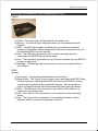
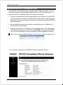
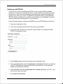
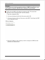
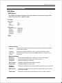
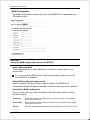
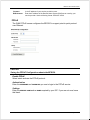
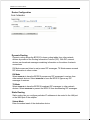
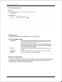
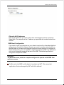
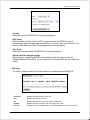
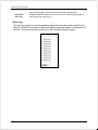
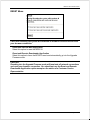
Broadband Phone Gateway BPG510
Technical Users Guide
(Firmware version 0.14.1 and later)
Revision 1.0
© 2006, 8x8 Inc.
BPG510 User Interface Guide
Table of Contents
About your Broadband Phone Gateway (BPG510)............................................. 4
Opening the BPG510's Configuration Utility ...................................................... 4
Connecting to Your Broadband Modem.............................................................. 6
Setting up with DHCP.......................................................................................... 6
Setting up with PPPoE ........................................................................................ 7
Connecting Local Computers .............................................................................. 7
Connecting a single computer............................................................................. 8
Connecting a local network ................................................................................. 8
Supporting a host server on the local network (port forwarding) ......................... 8
Setting up a DMZ ................................................................................................ 9
Detailed Screen Reference ................................................................................. 11
WAN Menu........................................................................................................ 11
WAN Status .................................................................................................... 11
WAN Configuration......................................................................................... 12
PPPoE ............................................................................................................ 13
MAC Cloning .................................................................................................. 13
LAN Menu ......................................................................................................... 14
LAN Configuration .......................................................................................... 14
DHCP Client Table ......................................................................................... 16
Router Configuration ...................................................................................... 18
Dynamic Routing ............................................................................................ 18
Static Routing ................................................................................................. 18
Port Forwarding .............................................................................................. 19
Filtering Configuration .................................................................................... 20
DMZ Host Configuration ................................................................................. 21
SYSTEM Menu ................................................................................................. 22
Set Security Password ................................................................................... 22
Localization..................................................................................................... 22
Call Log .......................................................................................................... 23
Error Log ........................................................................................................ 24
Handset Configuration.................................................................................... 24
Upgrade Firmware Menu................................................................................... 26
RESET Menu .................................................................................................... 27
Page 2 of 27
© 8x8 Inc., 2005
BPG510 User Interface Guide
About your Broadband Phone Gateway (BPG510)
FRONT
(1) Power – The Power light is solid green when the power is on.
(2) Service – The Service light is solid green when you are authenticated with
Packet8
(3) WAN – The WAN light is green to indicate that your modem is connected
properly to the Internet. It blinks rapidly when information is being sent over the
port between BPG510 and the modem.
(4) LAN – The LAN light is green when a PC or other networking device is
connected to the BPG510 with a network cable.
(5) Line – The Line light is green when you go off hook to indicate that your BPG510
is ready to make a call.
(6) Message – The Message light is green when you have a message waiting in
your mailbox.
REAR
(picture)
(1) Power Jack – Connect the included power cord to this jack.
(2) Reset Switch – The “Reset” button is used in rare cases when the BPG510 may
function improperly. Resetting the BPG510 will restore the BPG510’s normal
operation while maintaining the programmed settings. We recommend you
consult a Packet8 customer service representative before using this button.
(3) WAN – The WAN port is for connection to your cable or DSL modem or to
connect to your existing router.
(4) LAN – The LAN port is for connection to your computer or other networking
device.
(5) Line – The Line port is for connection to your telephone handset. Use the
telephone cable to connect the telephone to this port.
© 8x8 Inc., 2005
Page 3 of 27
BPG510 User Interface Guide
Opening the BPG510's Configuration Utility
Your BPG510 VoIP phone provides a browser-based configuration utility. You can
configured the phone using the same web browser you use to surf the Internet. To
open your phone's configuration utility, follow these instructions:
1. Connect a computer with a web browser directly to the LAN port of your BPG510.
(You may be able to connect to the BPG510 through a router or wireless access
point, but if you have any difficulty connecting, try connecting directly to BPG510’s
LAN Ethernet port.)
2. Be sure that this computer is configured to dynamically get an IP address (e.g.,
has the DHCP client enabled).
3. Type the IP address of your BPG510’s into the address bar of your web browser.
The default IP address of your BPG510 is 192.168.88.1. Then press the ENTER
key. You will be prompted to enter a password (the default password is admin).
Note: If you change the LAN IP address of your phone, be sure to make note of it.
4. You should now see the your BPG510’s System Information Screen:
Page 4 of 27
© 8x8 Inc., 2005
BPG510 User Interface Guide
If you have any trouble opening the utility, first check the connection between your
computer and the BPG510. Then, reboot your computer while it is connected to the
BPG510.
© 8x8 Inc., 2005
Page 5 of 27
BPG510 User Interface Guide
Connecting to Your Broadband Modem
Setting up with DHCP
The BPG510 is configured for use with Dynamic Host Configuration Protocol (DHCP)
by default. If your broadband connection uses DHCP, then you simply have to
connect your phone's WAN port to your broadband modem and then connect the
power on the phone. (See the BPG510 Router configuration Guide for detailed
connection diagrams.)
If you have disabled the DHCP client (for example, it you have used your phone in a
network requiring either PPPoE or a static IP address) and need to re-enable it,
follow the steps below:
1. Open the configuration utility.
2. In the menu bar down the left side of the screen, select WAN.
3. In the top menu bar, select WAN Settings. This will open the Wan Configuration
screen.
4. Select the radio button labeled OBTAIN WAN CONFIGURATION DYNAMICALLY.
5. Click SAVE WAN SETTINGS.
Page 6 of 27
© 8x8 Inc., 2005
BPG510 User Interface Guide
Setting up with PPPoE
Point to Point Protocol over Ethernet (PPPoE) is often used by DSL broadband
providers to connect and authenticate users on their networks. The service provider
will give you a user name and password, and usually some additional software you
need to run in order to go online. The BPG510 can take the place of the additional
PPPoE software, allowing you to establish and maintain your broadband connection
without running any extra programs on your computer.
Follow the steps below to configure the BPG510 to use a PPPoE-based connection:
1. Open the configuration utility.
2. In the menu bar down the left side of the screen, select WAN.
3. In the menu bar on the top of the screen, select PPPoE. This opens the WAN
PPPoE Configuration screen.
4. Under ENABLE PPPOE, click the drop-down arrow and select YES.
5. Under AUTHENTICATION, enter the USERNAME and PASSWORD that were provided by
your ISP. Username and password are often case-sensitive, so be sure enter
capital and small letters correctly.
6. Under SETTINGS, enter the SERVICE NAME and AC NAME required by your ISP. If you
are not sure, leave this blank.
7. Click SAVE PPPOE SETTINGS.
© 8x8 Inc., 2005
Page 7 of 27
BPG510 User Interface Guide
Connecting Local Computers
Connecting a single computer
If you want to connect a single computer to the Internet through your BPG510, use a
standard CAT5 Ethernet cable to connect the BPG510's LAN port to your computer's
Ethernet port. You may have to reboot your computer after you connect it to the
phone, but no other configuration should be necessary.
Connecting a local network
If you have more than one device you want to connect to the Internet, then you will
need to use an intermediary device such as a switch, a router, or a wireless access
point. We strongly recommend that you connect your BPG510 directly to your
broadband modem and connect your switch, router, or access point to the LAN port
of your phone. The BPG510 performs essential Quality of Service (QoS) function that
allows for superior voice quality. Placing any other device between the BPG510 and
your broadband modem, may reduce the quality of your VoIP phone calls due to the
traffic on your network.
Supporting a host server on the local network (port forwarding)
If you plan to set up a computer on your local network to host files or programs
accessible to the Internet, you will need to configure your BPG510 to forward the data
associated with the specific type of service you want to support (such as a web
server, an FTP server, game server, etc.) to the host server. Internet protocol
separates data traffic for different services into port ranges. To configure the BPG510
to forward any data that comes in on the port range of the service, follow the steps
below.
1. Determine the TCP/UDP ports used by the application you are hosting. A list of
commonly used ports can be found at http://www.iana.org/assignments/portnumbers.
2. Open the configuration utility.
3. In the menu bar down the left side of the screen, select LAN.
4. In the menu bar on the top of the screen, select Port Forwarding. This opens the
Port Forwarding Configuration screen.
Page 8 of 27
© 8x8 Inc., 2005
BPG510 User Interface Guide
5. Under Port Range, enter the first port of the range you want to forward in the first
box and the last port of the range in the second box. If the service you are
supporting only uses one port, enter the same port number in both boxes.
Ports in each range must be consecutive. If your service uses non-consecutive
ports, simply enter them as two separate port ranges.
6. Under Protocol, select whether the ports in the range are UDP ports, TCP ports, or
BOTH.
7. Under Destination Address, enter the IP address of the computer you want the
data sent to.
8. Click ADD. The BPG510 will add this port range to list of forwarded ports.
9. Repeat steps 5 through 8 for any additional ports ranges you want to forward. To
remove any port ranges from the list of forwarded ports, click the REMOVE button
beside the port range you want to delete.
Setting up a DMZ
If you want to have one computer on your network receive all un-forwarded data that
arrives at your firewall (for instance, because you want to monitor network traffic on
the WAN side or you have one computer running too many services to configure all
the forwarded ports), you can establish a single computer as a DMZ. Any data that is
not in a port forwarding range will be sent to the DMZ. Follow the steps below to
configure a computer as a DMZ.
© 8x8 Inc., 2005
Page 9 of 27
BPG510 User Interface Guide
CAUTION
The BPG510 cannot protect a computer running as a DMZ from malicious access.
Any computer running as a DMZ should be running a PC based firewall.
Traffic sent to the DMZ is still subject to translation by NAT. This means that
applications that are damaged by NAT will still be affected.
1. Open the configuration utility.
2. In the menu bar down the left side of the screen, select LAN.
3. In the menu bar across the top of the screen, select DMZ. This will open the DMZ
Host Configuration screen.
4. Enter the IP address of the computer you wish to configure as a DMZ and click
SAVE DMZ HOST CONFIGURATION.
Page 10 of 27
© 8x8 Inc., 2005
BPG510 User Interface Guide
Detailed Screen Reference
WAN Menu
WAN Status
The WAN Status screen displays information about the connection between the
BPG510 and the DSL or cable modem.
Interface Status
indicates the WAN interface has been activated. NO indicates the interface
has not been activated.
ENABLED
YES
PROTOCOL
Displays the protocol the BPG510 uses to communicate with the modem.
INTERFACE
STATUS
UP indicates the interface is functioning. DOWN indicates the interface is not
functioning.
Network Settings
DYNAMIC IP
ASSIGNMENT
Shows whether the BPG510 is configured to receive an IP address
automatically from the modem or the service provider.
IP ADDRESS
Displays the BPG510's IP address.
MAC ADDRESS
Displays the BPG510's MAC (hardware) address.
SUBNET MASK
Displays the BPG510's subnet mask.
DEFAULT
GATEWAY
Displays the IP address of the Default Gateway used by your service provider.
DNS ADDRESS
Displays the IP address of the Domain Name System (DNS) server used by
your service provider.
DOMAIN NAME
Displays the domain name of the WAN-side (service provider's) network.
© 8x8 Inc., 2005
Page 11 of 27
BPG510 User Interface Guide
WAN Configuration
The WAN Configuration screen allows you to set the BPG510 to operate with your
DSL/cable modem.
CAUTION
Saving the WAN Configuration reboots the BPG510.
Device Operating Mode
This section allows you to select BPG510 as a switch or a router device. If you
connect BPG
If you are connecting BPG510 as a client behind another router then you will
select BPG510 as a SWITCH.
Obtain WAN configuration dynamically
Select this option if you do not have a static IP address; the BPG510 will
automatically obtain its IP address and other information from your service provider.
Specify fixed WAN configuration
If your provider gave you a static IP address, select this option and fill out all the
information below:
IP ADDRESS
Enter the IP address you received from your service provider in the following
format: XXX.XXX.XXX.X
SUBNET MASK
Enter the subnet mask you received from your service provider in the following
format: XXX.XXX.XXX.X
DEFAULT
Enter the default gateway address in the following format: XXX.XXX.XXX.X This
Page 12 of 27
© 8x8 Inc., 2005
BPG510 User Interface Guide
GATEWAY
is the IP address of your service provider's router.
DNS ADDRESS
Enter the IP address of the Domain Name System (DNS) server used by your
service provider. Use the following format: XXX.XXX.XXX.X
PPPoE
The WAN PPPoE screen configures the BPG510 to support point-to-point protocol
over Ethernet.
CAUTION
Saving the PPPoE Configuration reboots the BPG510.
Enable PPPoE
Select YES to activate the PPPoE protocol.
Authentication
Enter the USERNAME and PASSWORD you use to login to the PPPoE service.
Settings
Enter the SERVICE NAME and AC NAME required by your ISP. If you are not sure, leave
this blank.
© 8x8 Inc., 2005
Page 13 of 27
BPG510 User Interface Guide
MAC Cloning
The MAC address is a unique hardware address assigned to each Ethernet device. If
your provider requires you to have a single MAC address, enter the MAC address
that your provider expects. The BPG510 will then transmit all packets as if they
originated from that MAC address.
LAN Menu
LAN Configuration
The LAN Configuration screen controls the IP address of the LAN port on the
BPG510. If you have an another device controlling IP address assignments on your
local network, you may need to change the BPG510's local IP address to place it on
the same network and subnet.
Page 14 of 27
© 8x8 Inc., 2005
BPG510 User Interface Guide
DHCP Server Configuration
The DHCP Server Configuration screen enables the router to automatically assign IP
address to attached computers using the Dynamic Host Control Protocol.
Server Configuration
Select ENABLED to activate the DHCP server and have the BPG510 assign IP
addresses for connected devices.
© 8x8 Inc., 2005
Page 15 of 27
BPG510 User Interface Guide
Client IP Address Range
Enter the range of IP addresses available to local devices. The BPG510 can support
32 IP addresses, and the address range must be consecutive numbers between 1
and 255.
Client Network Information
Domain Name
Enter the domain name used by the local LAN, if any.
DNS Server 1 & 2
Enter the IP addresses of the primary (1st) and secondary (2nd) DNS servers used by
the local LAN.
Static Address Assignments
Complete this information to make the BPG510 assign the same IP address to a
device every time. Assign a static IP address if the device serves as a host for any
Internet services. You can assign up to eight static IP addresses.
To assign new static IP addresses, click Add. Once a static IP address is assigned,
you can remove it by clicking the Remove button beside it.
Identify Using
Select whether you want to identify the local device by a HOST NAME of by the MAC
ADDRESS.
Host Identifier
Enter the name or the MAC address of the host.
Internal Address
Enter the IP address you want the DHCP server to assign to this device.
DHCP Client Table
The DHCP Client Table screen displays the name and ID (based on the MAC
address) of connected devices; it also shows the IP address and how long each
address is leased.
Page 16 of 27
© 8x8 Inc., 2005
BPG510 User Interface Guide
© 8x8 Inc., 2005
Page 17 of 27
BPG510 User Interface Guide
Router Configuration
Dynamic Routing
Dynamic routing allows the BPG510 to learn routing tables from other network
devices by means of the Routing Information Protocol (RIP). With RIP, network
devices can broadcast messages containing information on the status of network
connections.
RX Mode means we listen to and process RIP messages, TX Mode means we send
RIP information to other routers.
RX Mode
Select ENABLED to have the BPG510 process any RIP messages it receives from
other network devices. Select DISABLED to have the BPG510 ignore any RIP
messages it receives.
TX Mode
Select ENABLED to have the BPG510 broadcast RIP messages to other network
devices. Select DISABLED to prevent the BPG510 from broadcasting RIP messages.
Static Routing
Static routing lets you configure particular IP addresses to be routed to the LAN port
or the WAN port of the adapter.
Subnet Mask
Enter the subnet mask of the destination device.
Page 18 of 27
© 8x8 Inc., 2005
BPG510 User Interface Guide
Gateway IP
Enter the IP address of the gateway (i.e., the next router in the network path) to the
destination device.
Destination IP Address
Enter the IP address of the device you want to configure static routing for. Any
Ethernet packets destined for this IP address will be routed according to this
configuration.
Metric
Enter the metric associated with this static route. The Metric field corresponds
roughly to the number of hops it takes to get to the network or host being entered.
Interface
Select LAN to route packets destined for this device to the LAN port; Select WAN to
route packets destined for this device to the WAN port.
Port Forwarding
The Internet uses ports to specify different types of service requests. For instance, an
email message contains a code for port 110 (POP3 mail services) while a web page
request contains a code for port 80 (HTTP services). This allows the router to send
the requests to the correct host: any marked as port 110 is routed to the mail server,
and any data marked as port 80 is routed to the web server.
If you want to set up one or more computers as a host, you must tell the router what
services should be sent to that host. This configuration is called port forwarding.
There are over four thousand ports defined for different services. Of these, about one
thousand are used most often and considered “well-known” ports. Complete lists of
all well-known ports are available on the Internet; search for “well-known ports”.
© 8x8 Inc., 2005
Page 19 of 27
BPG510 User Interface Guide
Reserved Ports
The adaptor reserves ports 5060-5061 and 10000-10015.
Port Forwarding to LAN
PORT RANGE
Enter the first and last numbers of the port range you wan to map to
this computer. If you want to forward a single port only, enter the
same port number in both spaces.
NOTE: Port ranges are consecutive. If you need to assign nonconsecutive ports to a computer, you must enter that computer
twice with different port ranges.
PROTOCOL
Select TCP, UDP, or BOTH (TCP/UDP) according to the needs of your
network.
DESTINATION
ADDRESS
Enter the IP address of the computer you want to use as the host
computer for these services, then click ADD.
Filtering Configuration
The Filtering Configuration screen lets you block certain computers from accessing
the Internet or from accessing certain services on the Internet. You can filter
computers by IP address or by MAC address.
Page 20 of 27
© 8x8 Inc., 2005
BPG510 User Interface Guide
Filtered LAN IP Addresses
Enter the IP addresses you want to block from accessing the Internet connection.
Select Both. The computer at the IP address you specified will now be blocked from
Internet.
DMZ Host Configuration
If you want to have one computer on your network receive all un-forwarded data that
arrives at your firewall (for instance, because you want to monitor network traffic on
the WAN side or you have one computer running too many services to configure all
the forwarded ports), you can establish a single computer as a DMZ. Any data that is
not in a port forwarding range will be sent to the DMZ. Follow the steps below to
configure a computer as a DMZ.
CAUTION
The BPG510 cannot protect a computer configured to operate as the DMZ from
malicious access.
Traffic sent to the DMZ is still subject to translation by NAT. This means that
applications that are damaged by NAT will still be affected.
© 8x8 Inc., 2005
Page 21 of 27
BPG510 User Interface Guide
SYSTEM Menu
Set Security Password
New password
Enter the password you wan to use for this account.
Confirm new password
Enter the same password again for confirmation.
Localization
The Localization screen controls the time and place settings.
Page 22 of 27
© 8x8 Inc., 2005
BPG510 User Interface Guide
Country
Select the country the BPG510 is currently operating in.
NTP Server
Enter the Network Time Protocol (NTP) server you want the BPG510 to use to
automatically update the date and time settings. If you don't enter an NTP server, the
time and date stamp on Caller ID messages may not work correctly.
Time Zone
Select the time zone where the BPG510 is currently operating.
Adjust clock for daylight savings
Select this box to have the BPG510 automatically adjust the time one hour for
Daylight Standard Time (DST). If your area does not observe DST, do not enable this
option.
Call Log
The Call Log displays the last 10 calls received or transmitted by the BPG510.
DATE/TIME
Displays the date and time of the call.
LINE
Displays the line the call used.
I/O
Displays whether the call was inbound our outbound.
NUMBER
Displays the phone number of the other party to the call.
CALL-ID
Displays the Call-Id header value in the SIP messages. Your service provider
© 8x8 Inc., 2005
Page 23 of 27
BPG510 User Interface Guide
uses this information to locate/manage calls during troubleshooting.
AUDIO/RTP
STATISTICS
Displays RTP/RTCP statistics for the call (e.g. the number and percentage of
lost packets, jitter, latency etc.)
Error Log
The error log screen is used for gathering diagnostic information that could be used
later by a Packet8 technician to help investigate a network problem or a disruption of
service. This screen will be needed if you call Packet8 customer support
Page 24 of 27
© 8x8 Inc., 2005
BPG510 User Interface Guide
Handset Configuration
This section is to configure your connected analog telephone handset to command
advanced features.
Enable Simple Key Setting
Select this setting if you just want to enable simple key setting to your connected
handset.
Complex Key Settings (Advanced feature commands)
Select this setting if you want your connected telephone handset to use the following
feature.
Press “Flash” and then “1” on your connected telephone key pad for Hold/Unhold
command
Press “Flash” and then “*” on your connected telephone key pad for Alternate
command
Press “Flash” and then “7” on your connected telephone key pad for Conference
command
Press “Flash” and then “8” on your connected telephone key pad for Drop
Conference command
© 8x8 Inc., 2005
Page 25 of 27
BPG510 User Interface Guide
Upgrade Firmware Menu
Upgrades will automatically be performed by your BPG510 periodically as upgrades
become available. This feature is included to allow packet8 upgrading options for
future product enhancement
CAUTION
The Upgrade Firmware process will reset the unit into the Upgrade Firmware
mode. This will terminate all network connections and reset your browser
connection.
The Upgrade Firmware screen is used to update the firmware in your BPG510.
You should not use the Upgrade Firmware screen except on the advice of a
Customer Service Representative.
Page 26 of 27
© 8x8 Inc., 2005
BPG510 User Interface Guide
RESET Menu
CAUTION! Resetting the system will terminate all network connections and reset
your browser connection.
Reset and execute Main Application
Select this option to reset the BPG510.
Reset and Execute Downloader Application
Select this option to have the BPG510 reset and automatically go into the Upgrade
Firmware mode.
CAUTION
Resetting into the Upgrade Firmware mode will terminate all network connections
and reset your browser connection. You should not use the Reset and Execute
Downloader Application option except on the advice of a Customer Service
Representative.
© 8x8 Inc., 2005
Page 27 of 27