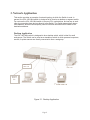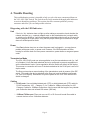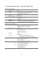
1
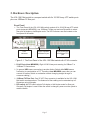
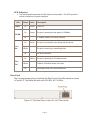
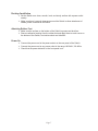
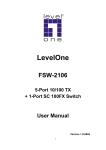
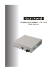
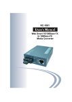
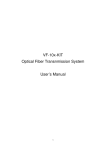
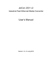
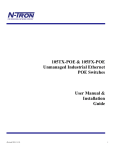
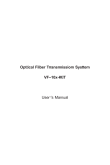
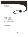
Volition
TM
Network Solutions
TM
VOL-1081
Fast Ethernet
Mini-switch 8+1
User Guide
ÿ Innovation
This page left blank intentionally
Page 2
Contents
1. Introduction...................................................................................................... 4
Figure 1-1. The VOL-1081 Fiber Switch .........................................................................4
Features ...............................................................................................................................4
2. Hardware Description...................................................................................... 5
Front Panel...........................................................................................................................5
Figure 2-1. The Front Panel of the VOL-1081 Mini-switch with VF-45 connector...........5
LED Indicators.....................................................................................................................6
Rear Panel............................................................................................................................6
Figure 2-2 The Rear Panel of the VOL-1081 Fiber Switch...............................................6
Desktop Installation .............................................................................................................7
Attaching Rubber Feet.........................................................................................................7
Power On ............................................................................................................................7
3. Network Application ........................................................................................ 8
Desktop Application ............................................................................................................8
Figure 3-1. Desktop Application ......................................................................................8
4. Trouble Shooting.............................................................................................. 9
Diagnosing with the LED Indicators ....................................................................................9
Link ....................................................................................................................................9
Power..................................................................................................................................9
Transmission Mode .............................................................................................................9
Cabling ...............................................................................................................................9
5. Technical Specifications - VOL-1081 Mini-switch ....................................... 10
Interfaces and Cabling........................................................................................................10
Standards and Performance ................................................................................................10
Power requirements............................................................................................................11
Physical and Environmental Specifications ........................................................................11
6.0 Agency Approvals ........................................................................................ 11
Electromagnetic and Safety Approvals ...............................................................................11
FCC Statement .................................................................................................................. 11
Page 3
1. Introduction
The VOL-1081 Mini-switch is a compact desktop size switch that is ideal for small office
or home office networks. It provides wire-speed, Fast Ethernet switching offering highperformance at low-cost.
Figure 1-1. The VOL-1081 Fiber Switch
ÿ The VOL-1081 Mini-switch provides 8 switched N-Way 10/100 Mbps RJ-45 Ethernet
ports and one 100Base-FX VF-45™ fiber port.
ÿ The Switch automatically detects the speed of the remote device to allow use of 10 and
100Mbps devices.
ÿ The Switch features store-and-forward switching and auto-learn of source addresses,
which it stores on a 4K-entry MAC address table.
ÿ The 100Base-FX VF-45 fiber port allows connections up to 2 Kilometers away.
Features
ÿ 8x 10/100Mbps Fast Ethernet UTP Switch ports
ÿ Automatic MDI/MDIX crossover for each 10Base-T/100Base-TX port
ÿ One 100Mbps Fast Ethernet Fiber (VF-45) port
ÿ One Dip-Switch to select fiber port full-duplex or half-duplex mode
ÿ N-way auto-negotiation supported
ÿ Full-duplex and half-duplex supported
ÿ Store-and-forward switching architecture for abnormal packet filtering
ÿ Full wire speed forwarding rate
ÿ 4K-entry MAC address table
ÿ 256KB memory buffer sharing
ÿ LED-indicators for power, 100M, LK/ACT, FD/COL statuses
ÿ Compact size
Page 4
2. Hardware Description
The VOL-1081 Mini-switch is a compact switch with 8x 10/100 N-way UTP switch ports
plus one 100Base-FX fiber port.
Front Panel
ÿ The Front Panel of the VOL-1081 Mini-switch consists of 8x 10/100 N-way UTP switch
ports (automatic MDI/MDIX), one 100Base-FX fiber port and one Dip-switch to select
fiber port full-duplex or half-duplex mode. The LED indicators are also located on the
front panel of the switch.
LED
indicators
VF-45 Connector
100Base-FX port
RJ-45 Connectors
10/100Base-T/TX
port
Figure 2-1. The Front Panel of the VOL-1081 Mini-switch with VF-45 connector
ÿ RJ-45 Ports (Auto MDI/MDIX): Eight 10/100 N-way auto-sensing for 10Base-T or
100Base-TX connections.
ÿ [In general, MDI means connecting to another Hub or Switch while MDIX means
connecting to a workstation or PC. Therefore, Auto MDI/MDIX means that you can
connect to another Switch or workstation without changing straight through or
crossover cabling.]
ÿ 100Base-FX Fiber Port: One VF-45™ fiber connector is available for the VOL-1081
Mini-switch as shown above. The distance for fiber cabling can be extended up to 2
kilometers using full duplex.
ÿ DIP-switch: the DIP-switch selects Full-duplex or Half-duplex mode for fiber port.
Generally Full-duplex is used. When the switch is changed, power must be cycled to
read the switch.
Page 5
LED Indicators
ÿ The following table describes the LED status and description. The LEDs provide a
real-time indication of system conditions.
LED
Power
Status
Color
Description
On
Green
Power On
On
Green
The port is operating at the speed of 100Mbps.
100 Mb
Off
On
In 10Mbps mode or no device attached
Green
The port is successfully connecting with the device.
Lnk /
Act
Blinks
The port is receiving or transmitting data.
Off
On
Fdx /
Col
Blinks
Off
No device attached.
Yellow
The port is operating in Full-duplex mode.
Collision of Packets occurs in the port.
Half-duplex mode or no device attached.
Rear Panel
The 3-pronged power plug is located at the Rear Panel of the Mini-switch as shown
in Figure 2-2. The Switch will work with 100-240V AC, 50-60Hz.
Figure 2-2 The Rear Panel of the VOL-1081 Fiber Switch
Page 6
Desktop Installation
ÿ Set the Switch on a clean, smooth, level, and sturdy surface with a power outlet
nearby.
ÿ Make sure there is enough clearance around the Switch to allow attachment of
cables, power cord and air circulation.
Attaching Rubber Feet
ÿ Make sure the surface on the bottom of the Switch is grease and dust free.
ÿ Remove adhesive backing from the rubber feet and apply them to each corner on
the bottom of the Switch, to minimize shock and vibration.
Power On
ÿ Connect the power cord to the power socket on the rear panel of the Switch.
ÿ Connect the power cord to any power outlet in the range 100-240 V, 50~60Hz.
ÿ Check that the power indicator on the front panel is on.
Page 7
3. Network Application
This section provides an example of network topology in which the Switch is used. In
general, the VOL-1081 Mini-switch is designed to be used as a desktop or segment switch.
You can use the VOL-1081 Mini-switch to connect PCs, workstations, and servers to each
other by connecting these devices directly to the Switch. The Switch automatically learns
node address, which are subsequently used to filter and forward all traffic based on the
destination address.
Desktop Application
The VOL-1081 Mini-switch is designed to be a desktop switch, which is ideal for small
workgroups. The Switch can be used as a standalone switch to which personal computers,
servers, or printer servers are directly connected to form a workgroup.
2 Km max.
fiber link
Remote
User’s
PC
Figure 3-1. Desktop Application
Page 8
4. Trouble Shooting
This troubleshooting section is intended to help you solve the most common problems on
the VOL-1081 Fiber Switch. The Switch can be easily monitored through panel indicators
to assist in identifying problems. This section describes common problems you may
encounter and where you can find possible solutions.
Diagnosing with the LED Indicators
Link
If the Lnk / Act indicator does not light up after making a connection check whether the
network interface (e.g., a network adapter card on the attached device), network cable,
or switch port is defective. Verify that the switch and attached device are on. Be sure the
cable is plugged in at both ends. Verify that the proper cable type is used and its length
does not exceed specified limits.
Power
If the Pwr indicator does turn on when the power cord is plugged in, you may have a
problem with power outlet, or power cord. However, if the Switch powers off after
running for a while check for loose power connections, power losses or surges at power
outlet.
Transmission Mode
The VOL-1081 RJ-45 ports use auto-negotiation to set the transmission mode (i.e., half
or full duplex). Verify that each attached device is configured to use auto-negotiation to
set the transmission mode. If auto-negotiation fails the switch will default to half duplex.
This means no connection will occur if the device attached to the RJ-45 port is set to full
duplex mode.
The fiber port requires a manual setting of the transmission mode by means of the DIP
switch. This means the device attached to the fiber port must be similarly configured
(i.e., half or full duplex). Remember to cycle the power on the VOL-1081 after the DIP
switch is changed.
Cabling
ÿ RJ-45 ports: Use unshielded twisted-pair (UTP) or shield twisted-pair (STP) cable for
RJ-45 connections: 100 Category 3, 4 or 5 cable for 10Mbps connections or 100
Category 5 cable for 100Mbps connections. Also be sure that the length of any twistedpair connection does not exceed 100 meters (328 feet).
ÿ 100Base-FX fiber port: Fiber port can use 50, or 62.5um multi-mode fiber cable to
connect devices over a 2-kilometer distance.
Page 9
5. Technical Specifications - VOL-1081 Mini-switch
Interfaces and Cabling
Copper
Connector
Impedance
Network Cables and
Distances
Fiber
Connector
Source, Wavelength
Optical budget
Sensitivity
Network Cables and
Distances
RJ-45 / 8 ports
100 ohm
UTP - 10Base-T: 2-pair Cat. 3, 4, 5 cable (100m),
UTP - 100Base-TX: 2-pair Cat. 5 cable (100m),
EIA/TIA-568 100-ohm STP (100m)
VF-45™ / 1port
LED, 1300 nm
11dB min. (62.5/125 um fiber)
7dB min. (50/125 um fiber)
-31dBm min.
100Base-FX: 50, 62.5/125 micron multi-mode fiber-optics
VF-45 Multi-mode: Full-duplex- 2Km, Half-duplex- 412m
Standards and Performance
Standards Compliance
Protocol
Architecture
Back plane
Performance
LED-indicators
IEEE 802.3 10Base-T Ethernet,
IEEE 802.3u 100Base-TX/FX Fast Ethernet
ANSI/IEEE 802.3 N-Way auto-negotiation
CSMA/CD
Store-and-forward switching
Abnormal packet filtering
4K-entry MAC address table
256KB memory buffer sharing
2.4 Gb /
2Mb Memory
Full wire speed forwarding / filtering rate:
14,880 pps per Ethernet port (10 Mbps) max.
148,800 pps per Fast Ethernet port (100 Mbps) max.
Pwr = Power
100Mb = 100 Mb/s operation
Lk/Act = Link / Activity
Fdx/Col = Full duplex operation / Collision
Port Features
VF-45
RJ-45
1 port, 100Mbps Fast Ethernet Fiber
Full-, half-duplex mode selected by dip-switch
8 ports, 10Base-T/100Base-TX
Automatic MDI/MDIX crossover
N-way Auto-negotiating
Full-, half-duplex support
Page 10
Power requirements
AC Input
Power consumption
100 to 240 Volts AC, 50 to 60Hz
Max. 12 Watts
Physical and Environmental Specifications
Dimensions
Switch
250 x 132 x 37 mm L x W x H, (9.84 x 5.19 x 1.47 inches)
Switch
1.01 kg (2.2 lbs.)
Weight
Temperature
Operating
Storage
0 to 45 °C (32 to 113 °F)
-40 to 70 °C (-40 to 158 °F)
Humidity
Operating/Storage
10 to 90% non-condensing
6.0 Agency Approvals
Electromagnetic and Safety Approvals
EMI
Safety
FCC Class B
CE Mark
UL 1950, cUL
FCC Statement
This equipment has been tested and found to comply with the limits for a class B device, pursuant
to part 15 of the FCC rules. These limits are designed to provide reasonable protection against
harmful interference in a commercial installation. This equipment generates, uses and can radiate
radio frequency energy and, if not installed and used in accordance with instructions, may cause
harmful interference on radio communications. Operation of this equipment in a residential area is
likely to cause harmful interference, in which case, the user will be required to correct the
interference at the user’s own expense.
Page 11
3M, Volition, VF-45, and the “dot wave” symbol are trademarks of 3M
Important Notice
Before using this product, you must evaluate it and determine if it is suitable for your intended application. You assume all risks and
liability associated with such use.
Warranty; Limited Remedy; Limited Liability
This product will be free from defects in material and manufacture for a period of one year from the date of purchase. 3M MAKES NO
OTHER WARRANTIES INCLUDING, BUT NOT LIMITED TO, ANY IMPLIED WARRANTY OF MERCHANTABILITY OR
FITNESS FOR A PARTICULAR PURPOSE. If this product is defective within the warranty period stated above, your exclusive
remedy shall be, at 3M’s option, to replace or repair the 3M product or refund the purchase price of the 3M product. Except where
prohibited by law, 3M will not be liable for any loss or damage arising from this 3M product, whether direct, indirect, special,
incidental or consequential regardless of the legal theory asserted.
ÿ
Telecommunications
6801 River Place Blvd.
Austin, TX 78726-9000
800/695-0447
© 3M IPC 2001
78-8110-6189-0-A
Page 12