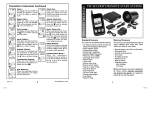
1
Installation
and Owner’s
Manual
Model: X3
For Technical Assistance, please call (800) 638-3600,
or visit www.magnadyne.com
This device complies with part 15 of the FCC rules. Operation is subject to the following two conditions:
(1) This device may not cause harmful interference; and
(2) This device must accept any interference received, including interference that may cause undesired operation.
Note: The manufacturer is not responsible for any radio or TV interference caused by unauthorized modifications to this
equipment. Such modifications could void the user’s authority to operate the equipment.
Table of Contents
Component Installation . . . . . . . . . . . . . . . . . . . . . . . . . . . . . . . . . . . . . . . . . . . . . . . . . . . . . . . . . . . . . . . .
Wiring
White 12-Pin Main Harness . . . . . . . . . . . . . . . . . . . . . . . . . . . . . . . . . . . . . . . . . . . . . . . . . . . . . . . . . . .
Wiring Harness Quick Reference . . . . . . . . . . . . . . . . . . . . . . . . . . . . . . . . . . . . . . . . . . . . . . . . . . . . . . .
Black 3-Pin Door Lock Harness . . . . . . . . . . . . . . . . . . . . . . . . . . . . . . . . . . . . . . . . . . . . . . . . . . . . . . . .
Optional Wiring Suggestions . . . . . . . . . . . . . . . . . . . . . . . . . . . . . . . . . . . . . . . . . . . . . . . . . . . . . . . . . . .
Programming the Transmitter . . . . . . . . . . . . . . . . . . . . . . . . . . . . . . . . . . . . . . . . . . . . . . . . . . . . . . . . . . .
Alarm Feature Programming . . . . . . . . . . . . . . . . . . . . . . . . . . . . . . . . . . . . . . . . . . . . . . . . . . . . . . . . . . . .
Shock Sensor Testing and Adjustment . . . . . . . . . . . . . . . . . . . . . . . . . . . . . . . . . . . . . . . . . . . . . . . . . . . .
Owners Manual . . . . . . . . . . . . . . . . . . . . . . . . . . . . . . . . . . . . . . . . . . . . . . . . . . . . . . . . . . . . . . . . . . . . . .
2
2-5
3
6
5-6
6-7
7-8
9
9-12
Component Installation
Mounting the Control Module:
Find a suitable location to secure the alarm control module within the passenger’s compartment of the vehicle.
Never mount the alarm control module in the engine compartment or in the trunk. In addition, never mount the
alarm control module in the direct path of the heater. Secure the alarm control module by using wire ties or drill
two 1/8" holes and secure the module to the frame of the vehicle with the screws provided.
Valet Switch
Select a mounting location for the switch that is easily accessible to the driver of the vehicle. The switch does
not have to be concealed. However, concealing the switch is always recommended, as this provides an even
higher level of security to the vehicle. Mount the valet switch in a hidden but accessible location. Route the valet
switch wires to the control module.
LED Status Indicator
The LED status indicator should be mounted in a highly visible area. Leave at least 6mm of space behind the
mounting location for LED housing. Once a suitable location is chosen, drill a 1/4" hole. Run the LED wires
through the hole then press the 2-pin LED housing into the place. Route the LED wires to the control module.
Antenna Wire
For maximum possible range, keep the antenna wire away from the alarm harnesses. Stretch out the antenna in
another direction and keep it as straight as possible. Do not connect the antenna wire to ground. Do not
lengthen or shorten the antenna wire. Do not coil or wind the antenna wire around another harness.
Wiring
HC4: White 12-Pin Main Harness
The main wire harness contains 11 wires which all have a specific purpose. Follow the wiring recommendations
enclosed for each wire. Wires not used should be released from the harness connector or taped off to prevent
accidental shorting.
Yellow Wire: +12VDC Ignition Input
Connect the Yellow wire to a +12 volt wire that is switched on and off by the ignition key. The correct wire will
indicate +12 volts when the ignition key is in the on and start positions. Do not connect the yellow wire to the
“ACC” wire coming from the ignition switch.
Green Wire: (-) Common Door Pin Input
The green wire connects to the common wire of the vehicle that switches on the dome light. Normally this wire is
located at one of the door jamb switches. For some vehicles it may be necessary to connect the green wire directly
to the switched turn on wire at the dome light. The green wire connects to negative switched circuits only.
Blue Wire: (-) Hood / Trunk / Auxiliary Trigger Input
The blue wire is an instant grounding trigger input for optional hood/trunk grounded pin switches or any
electronic sensor.
2
Wiring Harness Quick Reference
HC4 12-Pin Main Harness
Yellow
+12VDC Ignition Input
Green
(-) Common Door Pin Input
Blue
(-) Hood / Trunk / Auxiliary Trigger Input
Violet
(+) Common Door Pin Input
Orange
(-) Ground when Armed Output
Open
No Connection
Red/White (-) 300mA Programmable Channel 3 (Trunk) Output
Black
Chassis Ground
Brown
(-) Siren Output
White/Red
(+/-) Parking Light Relay Input
Red
+12VDC Battery Input
White
(+/-) Parking Light Relay Output
HC3 3-Pin Door Lock Harness
Green
(-) Lock
Open
No Connection
Blue
(-) Unlock
Wiring (continued)
Violet Wire: (+) Common Door Pin Input
The violet wire connects to the common wire of the vehicle that switches on the dome light. Normally this wire is
located at one of the door jamb switches. For some vehicles it may be necessary to connect the violet wire directly
to the switched turn on wire at the dome light. The violet wire connects to positive switched circuits only.
Orange Wire: (-) Ground when Armed Output
The orange wire is typically connected to an optional starter disable relay as shown.
SPDT 30A Relay
(Not Supplied)
Orange Wire
(Ground when Armed Alarm Output)
87
87a
85
86
30
"OFF"
"ACC"
"IGN"
Starter
"START"
Black
Cut
Black
3
Wiring (continued)
Red/White Wire: (-) 300mA Programmable Channel 3 Output (Default Trunk Release)
The Red/White wire is typically used to release the power trunk by remote. An additional relay is usually
required as shown in the diagram below. This wire can also be programmed for Domelight Supervision Control
or 2nd unlock function (See Alarm Feature Programming to change the setting)
Output to Power Trunk Switch
87
Red/White Wire
(SPST ALA984H
Relay Not Supplied)
To Constant +12 Volts
86
30
85
Input to Relay (+ or -)
Black Wire: Chassis Ground
This is main ground connection of the alarm module. Make this connection to a solid section of the vehicle
chassis. Do not connect this wire to any existing ground wires supplied by the factory wire loom, make the
connection to the vehicle’s chassis directly.
Vacant Socket: No Connection
Brown Wire: (-) Siren Output
Connect the brown wire to the Negative wire from an electronic siren (Siren Supplied). Connect t the remaining
wire from the siren to +12 volt. (Battery +)
The Brown wire can also be programmed for (-) horn honk output. (See Alarm Feature Programming to change
the setting)
White/Red Wire: (+/-) Parking Light Relay Input
The white/red wire is the input to the flashing parking light relay. The connection of the white/red wire will
determine the output polarity of the flashing parking light relay. Connect the white/red wire to (+) battery to have
(+) output from the relay or connect the white/red wire to chassis ground to have ground output from the relay.
Red Wire: +12VDC Battery Input
Connect the Red wire directly to the (+) battery post for best operation of the alarm system.
White Wire: (+/-) Parking Light Relay Output
Connect the white wire to the parking light wire coming from the headlight switch. Do not connect the white
wire to the dashboard lighting dimmer switch – Damage to the dimmer will result. Use a volt meter to test the
connection point before connecting the white wire. While checking, rotate the dimmer switch to make sure you
do not have the dimmer lead. The limitation of the white wire is 10 Amp max. Do not exceed this limit or
damage to the alarm and parking light relay will result.
Headlight Switch
White Wire
4
Piggyback
Connection
Parking
Lights
Only
Wiring (continued)
HC3: Black 3-Pin Door Lock Harness
Blue Wire: (-) Door Unlock Control
Connect the Blue wire to the unlock wire from the door lock switch. If the door locking system is not a (-)
trigger system, additional relays will be required.
Green Wire: (-) Door Lock Control
Connect the Green wire to the lock wire from the door lock switch. f the door locking system is not a (-) trigger
system, additional relays will be required.
3 Wire Ground Trigger Door Lock System
Green Wire: Connect to Lock
Blue Wire: Connect to Unlock
Black 3-Pin
Mini Connector
(-) Lock Out
Lock Control
Switch
Ground Input
To Door Lock
Control Relays
(-) Unlock Out
P1: LED Status Indicator
P2: Valet Switch
Optional Wiring Diagrams
Red/White Wire: (When programmed for (-) 2nd Unlock Output)
When Programmed for this function, the Red/White wire provides a second (-) unlock output to unlock the
passenger’s doors. Use the “Blue Wire” on the Black 3 pin connector to unlock the drivers door.
Unlock Driver's Door First for 3-Wire Negative Door Lock Systems
Green Wire
Blue Wire
87
Red/White Wire
87A
85
Driver's Door
Switch
Lock
86
30
Unlock
Lock
To +12V or Ground
Driver's Door
Unlock Wire
+12V
ALA984H
Relay
Cut
Unlock
Door Lock Relay
Control Module
Passenger's
Door Switch
To +12V or Ground
Passenger's Door
5
Optional Wiring Diagrams
Red/White Wire: (When programmed for (-) Domelight Supervision Output)
When Programmed for this function, the Red/White wire provides a (-) output to turn on the vehicles interior
light when the alarm has been disarmed. The domelight will stay on for 30 seconds unless the ignition key is
on.
Output to Dome Light (+ or -)
87
Red/White Wire
(SPST ALA984H
Relay Not Supplied)
To Constant +12 Volts
86
85
30
Input to Relay (+ or -)
Brown Wire: (When programmed for (-) Horn Output)
When Programmed for this function, the Brown wire provides a (-) output to use the vehicles horn as the
primary sounding device. Locate the horn button wire at the base of the steering column.
Note: Some vehicles will require an additional relay.
To Horn
Fuse
87
Brown Wire
To +12V
87a
85
86
30
+12V or Ground Depending
on System Requirements
Programming the Transmitter
Programming the Remote Transmitter
Note: This mode will only retain the last 4 remote transmitters programmed. If the transmitter memory is
exceeded, the security system will start deleting transmitters from memory in chronological order.
Step 1
Step 2
3X
With the ignition switch in the OFF position, turn the
key On
6
Before 15 seconds has passed, push and release the valet
switch 3 times. THe siren will emit 1 long + 1 short chirp.
You are now in “Transmitter Programming” mode.
Programming the Transmitter
Step 3
Step 5: Exit Program Mode
Step 4
Press the “Lock” button on the first
transmitter until you hear a
confirmation chirp/beep. The
transmitter is now coded into the
system.
Repeat for each additional
transmitter.
When finished, turn Off the ignition
key or wait for 15 seconds to get out
of transmitter programming mode.
You will hear 3 long chirps/beeps.
You are out of the transmitter
programming mode.
Alarm Feature Programming
Examine the feature chart enclosed and decide which feature will get changed. Circling the feature to be changed
will make the programming process much easier to perform.
Step 2
Step 1
+
3X
With the ignition switch in the OFF position, turn the
key On-Off
Step 3
3X
Within 10 seconds, push and release the valet switch 3
times. The siren/horn will emit 1 long chirp or beep.
Push and release the valet switch 3 more times. The
siren/horn will emit 1 long chirp or beep. You are now
in “Alarm Feature Programming” mode.
1. Press the valet switch the number of times required to access the feature that needs
adjusting.
2. Press the indicated transmitter button and listen for the chirp sequence to set the
feature.
Example:
- Complete steps 1,2 and 3 to enter feature program mode
- Push the valet switch 2 times, (Selects Manual/Automatic arm
programming) the siren will chirp 2 times and the LED will flash
2 times.
- Change the feature to “Automatic Arming” by Pressing the button
on the transmitter. The siren/horn will chirp 2 times.
7
Alarm Feature Programming (continued)
Press TX Button
Press
LED Flash/
Valet
Chirp
Switch
Press TX Button
One Chirp
(Default Setting)
Press TX Button
Two Chirps
Press TX Button
Three Chirps
1
1
Chirps “On”
Chirps “Off”
2
2
Manual Arming
Automatic Arming
without Door Locking
3
3
Ignition On/Off with
Door Lock/Unlock
Ignition On/Off without
Door Lock/Unlock
4
4
Auto Rearm “Off”
Auto Rearm “On”
.8 Sec Door Lock/
Unlock Output
Car-Jacking “Off”
3.5 Sec Door Lock/
Unlock Output
.8 Sec Double
Unlock Output
Automatic Arming
with Door Locks
5
5
6
6
Manual Car-Jack “On”
Automatic Car-Jack “On”
7
7
HC4 Red/White Wire
(-) Channel 3 Output
HC4 Red/White Wire
(-) Domelight Output
HC4 Red/White Wire
(-) 2nd Unlock Output
8
8
Trunk Release
Disarm On
Trunk Release
Disarm Off
9
9
Alarm/Keyless
Entry Mode
10
10
HC4 Brown Wire
Siren Output
11
11
Instant Door
Ajar Warning
Door Ajar Warning
with 45 Second Delay
12
12
Standard Horn
Pulse Output
“SOS” Type
S-S-S - L-L-L - S-S-S
Keyless Entry
Only Mode
(No Alarm Functions)
(No Carjacking Functions)
HC4 Brown Wire
Pulsed Siren Output
HC4 Brown Wire
Horn Output
S-L-S-L
4-chirp S-S-S-L
5-chirp S-M-L-S-M-L
6-chirp SS - L - S-S
Turn On the Ignition
3 long chirps will confirm exit of the programming
mode.
Step 4: Exit Program Mode
Note: Waiting 15 seconds after the last command will
also cause the system to automatically exit the
programming mode.
Shock Sensor Testing and Adjustment
Step 1
Step 2
3X
Turn the ignition switch from the
OFF position to the ON position 3
times leaving it in the Off position
the third time.
8
Step 3
5X + 1X (Hold)
Before 15 seconds has passed,
push and release the valet switch 6
times. Hold the button down on the
6th press until 3 short chirp/beeps
and 1 long chirp/beep is heard then
release it.
Press and release the ( )
button for 2 seconds. You will hear
1 long siren/horn chirp. You are now
in the “Primary Trigger Shock
Sensor Test mode”.
Shock Sensor Testing and Adjustment
Step 5
Step 6
1. Press and hold the LOCK and
UNLOCK buttons together for 2
seconds. You will hear 2 long
siren/horn chirp. You are now in the
“Pre-warning” trigger Shock Sensor
test mode.
2. Follow the procedures in Step 4 to
adjust the “Pre-warning”sensitivity.
To exit the shock sensor test mode,
turn ignition “On” and 3 long chirps
will confirm exit of the “Shock
Sensor” test mode.
Note: 30 seconds of inactivity will
force exit of the shock sensor test
mode.
Step 4
Increase
Decrease
1. Press the LOCK button to
increase sensitivity by 1 step
(1 chirp)
2. Press the UNLOCK button to
decrease the sensitivity by 1 step
(1 chirp)
3. Rap on the vehicle body panels
and glass to achieve the proper
setting.
Note: If you hear 2 chirps while
making an adjustment, you have
reached the max setting.
Owners Manual
A. Transmitter Operation
Lock/ Arm
Car-Finder
B. Alarm Status Indicators
Un-Lock/
Disarm
2nd
System
CH#3
(Trunk)
Panic
LED Indications
LED is off = Alarm is disarmed.
LED is flashing normal = Alarm is armed.
LED is flashing fast = Automatic Arming Countdown.
LED is on (solid) = Valet Mode.
LED flashes twice then pauses = Tamper warning, alarm was triggered by an
open trunk or hood.
LED flashes three times then pauses = Tamper warning, alarm was triggered
by an open door.
LED flashes four times then pauses = Tamper warning, alarm was triggered by
the shock sensor.
LED flashes five times then pauses = Tamper warning, alarm was triggered by
voltage from the ignition switch turning on.
Chirp Indications
One siren chirp = Security system is armed.
Two siren chirps = Security is disarmed.
Four chirps = Tamper disarm warning, alarm was previously triggered.
Two sets of two chirps = Stage 1 of progressive car finder
Two sets of three chirps = Stage 2 of progressive car finder
Six chirps = Stage 3 of progressive car finder
Parking Light Indications
Parking lights flash one time upon arming = Security system is armed.
Parking lights flash two times upon disarming = Security system is disarmed.
Parking lights flash three times upon disarming = Tamper disarm warning,
alarm was previously triggered.
Parking lights flash three times while armed = Stage 1 and 2 of progressive car
finder
Parking lights flash six times while armed = Stage 3 of progressive car finder
9
Owners Manual (Continued)
Button Function:
Transmitter Button
+
Action
System Function / Remark
Press and Release
Arm/Lock Doors
Press Twice
Arm/Lock Doors + Delete Shock Sensor (2nd Long Beep)
Press and Release
Progressive Car Finder (Functions 30 Seconds After Armed)
Press and Release
Disarm/Un-Lock Doors
Press and Hold for 1.5 Seconds
Channel 3 Activation (Release Trunk as Default)
Press Both Buttons Together
Silent Arm/Disarm (Ignition Key is Off)
Press and Hold Both Buttons
for 1 Second
Activate Car-Jacking (Ignition Key Must be On)
Press and Hold for 3 Seconds
Press and Hold for Panic Mode On
Press and Release for Panic Mode Off
Press and Release
Activate 2nd System operation
C. Dual-Zone Shock Sensor
1. Light impacts to the vehicle will cause a pre-warning (warn-away) chirp from the siren or horn. These
light impacts will not set the alarm into full trigger even if they are repetitive.
2. Hard impacts to the vehicle will bypass the pre-warning indicator and activate a full alarm trigger.
D. Manual Arming “Lock”
1. Press the “Lock” button on the transmitter.
2. The siren will chirp once and the parking light will flash once indicating that the system is now armed.
The vehicle’s doors will lock upon arming if door lock control has been installed.
Silent Arming/Disarming: Press the “Lock” and “Unlock” button together on the transmitter to arm or
disarm you security system. No chirp sound will be heard, arm/disarm confirmation will be through the
vehicles parking lights only.
E. Automatic Arming
This X3 security system is equipped with an optional Automatic Arming feature, which allows the security
system to arm 30 seconds after the last door is closed.
Operation:
1. Turn the ignition to the “Off” position and exit the vehicle.
2. After all entrances are closed the security system’s LED will flash fast for 30 seconds. If you reopen any
protected entrance, the security system LED will stop flashing. It will begin flashing again once all the
protected vehicle’s entrances are closed.
3. After the 30-second timer has elapsed, the security system will automatically “Arm”. The siren will chirp
one time and the parking lights will flash one time.
Passive Door Locking: If the “Automatic Arming with Door Locks” feature has been programmed on, The
vehicle doors will automatically lock after the automatic arming cycle has been completed. (see Feature No.
2 on programming chart)
10
Owners Manual (Continued)
F. Manual Disarming “Unlock”
1. Press the “Unlock” button on the transmitter.
2. The siren will chirp twice and parking lights will flash twice indicating that the security system is now
disarmed. The vehicle doors will unlock disarming when interfaced with the security system.
Tamper Disarming: If alarm is triggered upon disarming the system, the siren chips 4 times and the
parking lights flash 3 times.
Automatic Rearm: (see feature No. 5 on programming chart) If this feature is selected, the security system
will automatically rearm itself 60 seconds after disarming with remote transmitter. Automatic rearm will
cancel if any door is opened before the 60 seconds timer has elapsed.
G. Valet Mode
The valet switch allows you to temporarily bypass all alarm functions, eliminating the need to give your
transmitter to parking attendants or garage mechanics. When the system is in valet mode, all alarm
function are bypassed, however the remote panic feature and remote door locks will remain operational.
Enter Valet Mode:
1. Turn the ignition to the “On” position.
2. Push and hold valet switch for 2 seconds until the LED turns on. The LED will remain on as long as the
system is in the Valet Mode.
Exit Valet Mode:
1. Return to normal operation, turn ignition “On”.
2. Push and hold the valet switch for 2 seconds, the LED will turn off to indicate the system is exiting the
valet mode.
H. Panic Function
The transmitter can be used as a remote panic switch to manually trigger the alarm in case of emergency.
1. Press and hold the “Star” button on the transmitter for 3 seconds. The alarm will immediately sound.
2. To stop the panic alarm, press and release any button on the transmitter, the panic mode will be turned off
immediately.
3. If the button is not pressed, the panic alarm will automatically stop after 60 seconds.
I. 60 Second Rearming
If your security system has become triggered, the siren will sound for 60 seconds and then stop and reset
to a fully armed condition.
Note: If the alarm system has been triggered from the following inputs (Trunk/Shock sensor - Ignition key
on or Door open), and an input remains in a triggered state (a door left open for example) your security
system will remain triggered for three 60 second cycles then it will fully rearm and excluding the input that
triggered it . When the excluded trigger is corrected (the door is closed for example) the entrance will reset
the door input trigger within 3 seconds.
J. Progressive Car Finder
Use your remote control to locate your vehicle in a crowded parking lot or structure. Note: The alarm
system must be armed for more than 30 seconds before the car finder feature will operate.
A. Press the LOCK button on the transmitter. The siren or horn will blast two times and then blast again
two more times. The parking lights will flash three times with each blast.
B. Press the LOCK button on the transmitter again within 30 seconds. The siren or horn will blast three
times and then blast again three more times. The parking lights will flash three times with each blast.
C. Press the LOCK button on the transmitter again within 30 seconds. The siren or horn will blast six
times. The parking lights will flash six times with each blast.
11
K. Anti Car-Jacking (Manual Activation)
Warning: If you don’t need this alarm system’s car-jacking function to be “On”, set it to “Off”. The default
car-jacking setting is “Off” (see Feature No. 6 on programming chart).
Pressing and holding the “Lock” and “Unlock” button on the transmitter for 1 second while the vehicle’s
ignition is “On” will trigger the car-jacking. The parking lights will turn on for 1.5 seconds to indicate carjacking is activated.
1. 60 seconds after the system has been triggered, the siren starts alarming and the parking lights start
flashing.
2. 90 seconds after the system has been triggered.
A. The siren will still be sounding and the parking light flashing and,
B. The starter disable will activate to prevent the vehicle from being restarted,
C. It will remain active until the vehicle’s battery power is exhausted.
L. Anti Car-Jacking (Automatic Activation)
Warning 1: If you don’t need this alarm system’s car-jacking function to be “On”, set it to “Off”. The
default car-jacking setting is “Off” (see Feature No. 6 on programming chart).
Warning 2: When this feature is programmed for “Automatic Mode” operation, the car-jacking feature is
armed at all times when the ignition key is on. Opening any protected entrance while the vehicle’s ignition
is “On” will trigger the car-jacking system.. The parking lights will turn on for 1.5 seconds to indicate carjacking is activated.
1. 60 seconds after the system has been triggered, the siren starts alarming and the parking lights start
flashing.
2. 90 seconds after the system has been triggered.
A. The siren will still be sounding and the parking light flashing and,
B. The starter disable will activate to prevent the vehicle from being restarted,
C. It will remain active until the vehicle’s battery power is exhausted.
Override the System to Turn Off Car-Jacking:
Turn the ignition switch from “Off” to “On”, and within 10 seconds push valet switch, the siren will stop and the
system will disarm.
© Copyright 2008-2009 Magnadyne Corporation
X3-IMUM 7-24-08 Rev. A