1
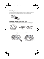
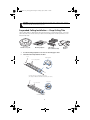
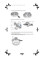
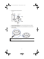
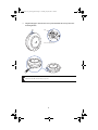
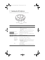
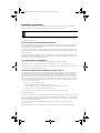
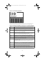
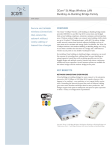
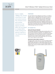
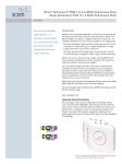
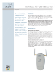
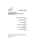
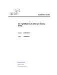
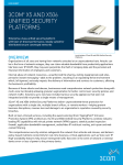
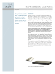
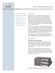
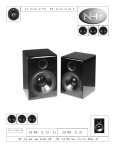
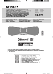
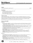
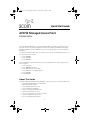
10015414-AA_AP3750_QSG.fm Page 1 Tuesday, July 25, 2006 1:59 PM
Quick Start Guide
AP3750 Managed Access Point
3CRWX375075A
The 3Com AP3750 Managed Access Point provides IEEE 802.11a and 802.11b/g wireless access to
the network. The access point is designed for use with a 3Com Wireless LAN Switch, and requires
hardware installation only. All configuration for the access point takes place on the 3Com Wireless
LAN Switch.
You must have a wireless switch device to operate the access point. Three WLAN switch devices can
be connected to the access point:
•
•
•
3Com WX4400
3Com WX1200
3Com WXR100
Power is supplied via Power Over Ethernet (PoE). The following 3Com PoE devices supply power to
the access point:
•
•
•
•
•
•
3Com PoE Injector
3Com 4400PWR PoE Switch
3Com Multi-port PoE power supply
3Com 5500 Series PoE capable switches
3Com WX1200
3Com WXR100
About This Guide
This Quick Start Guide describes the basic installation of the access point. It covers the following topics:
•
•
•
•
•
•
•
•
•
3Com AP3750 Managed Access Point Features
Observing Safety Precautions
Step 1: Unpacking the Access Point
Step 2: Preparing for Installation
Step 3: Connecting External Antennas
Step 4: Mounting the Access Point
Step 5: Connecting the Access Point to a Switch
Step 6: Configuring the Access Point
Step 7: Checking the LED Indicators
1
10015414-AA_AP3750_QSG.fm Page 2 Tuesday, July 25, 2006 1:59 PM
3Com AP3750 Managed Access Point Features
Diameter
16.76 cm
(6.6 inches)
Height
4.69 cm
(1.85 inches)
840-9502-0040
TM
External antenna
connectors
Kensington security
slot
802.11b/g
840-9502-0007
Unlock
802.11a
RJ-45
ports
Port 2
Port 1
Kensington Security Slot
The access point has a slot for attachment of a Kensington security cable. The cable is not included with
the access point but can be ordered separately.
Lock and Unlock Holes
On one side of the access point there is a lock hole. On the other side there is an unlock hole. Insert a
3-mm or 1/8-inch screwdriver into the appropriate hole to attach and remove the access point from the
mounting bracket.
CAUTION: To prevent possible damage to the access point, do not use excessive force when
inserting a tool into the lock or unlock hole.
2
10015414-AA_AP3750_QSG.fm Page 3 Tuesday, July 25, 2006 1:59 PM
RJ-45 Cable Ports
The access point has two RJ-45 ports. Each port provides a 10/100BASE-TX Ethernet connection to a WX
switch. The connection can be direct to an WX switch or indirect through an intermediate Layer 2 or
Layer 3 network.
The access point receives power and data through the RJ-45 ports. Use a Category 5 (Cat 5) cable with
straight-through signaling and standard RJ-45 connectors to connect an access point to a WX switch or
other device in the network. The access point supports 802.3af, and also can receive PoE from 3Com
switches and 3Com-approved power injectors.
The two RJ-45 ports support dual-homed configurations for redundancy. The access point uses only one
link for booting, configuration, and data transfer. If the link becomes unavailable, the access point can
reboot using the other link.
The ports are identical except for logical numbering (1 or 2). You can use either port to connect the
access point to a WX switch. However, the access point always attempts to boot on port 1 first. Only if
the boot attempt on port 1 fails does the access point attempt to boot on port 2. If one port becomes
unavailable, the other port can provide full power to the access point.
Note: The access point does not support daisy-chain configurations. Do not connect the access point
to another AP3750 access point.
External Antenna Connectors
The access point has connectors for attaching optional external antennas. See “Connecting External
Antennas” on page 5 for more information.
Observing Safety Precautions
This equipment must be installed in compliance with local and national building codes, regulatory
restrictions, and FCC rules. For the safety of people and equipment, only professional network personnel
should install the access point
.\
WARNING: To comply with FCC radio frequency (RF) exposure limits, a minimum body-to-
antenna distance of 20 cm (8 inches) must be maintained when the access point is operational.
WARNING: To avoid possible injury or damage to equipment, you must use power supply equipment
that is safety certified according to UL, CSA, IEC, or other applicable national or international safety
requirements for the country of use. All references to power supply in this document refer to equipment
meeting these requirements.
WARNING: Do not operate the access point near unshielded blasting caps or in an otherwise
explosive environment unless the device has been modified for such use by qualified personnel.
WARNING: Do not touch or move the access point when the antennas are transmitting or receiving.
WARNING: Do not hold any radio device so that the antenna is very close to or touching the face,
eyes, or other exposed body part while the device’s radio antenna is transmitting.
3
10015414-AA_AP3750_QSG.fm Page 4 Tuesday, July 25, 2006 1:59 PM
WARNING: Before using a wireless device in a hazardous location, consult the local codes, national
codes, and safety directors of the location for usage constraints.
WARNING: Do not connect or disconnect cables or otherwise work with the access point
hardware during periods of lightning activity.
NOTE: The access point is intended for indoor use only. Do not install the device outdoors,
unless you install it in a properly installed enclosure.
NOTE: To reduce the possibility of connection interference caused by dust, clean the
Category 5 connector pins before inserting a cable into the access point.
1 Unpacking the Access Point
Make sure that you have the following items, which are included with the access point:
•
•
Mounting Kit:
• One universal mounting bracket (attached to the access point)
• One paper mounting template (used for marking cutting areas and screw holes)
• One two-piece 14.2-mm (9/16-inch) T-bar clamp
• One two-piece 15.9-mm (5/8-inch) T-bar clamp
• One two-piece 23.9-mm (15/16-inch) T-bar clamp
• Two #6 sheet metal screws and two drywall anchors
Three adhesive rubber feet (used for a tabletop installation).
2 Preparing for Installation
It is advisable to connect the power (if using an external power supply) and check the Ethernet cables
and LEDs before installing the access point in a hard-to-reach location. Additionally, observe the
following before mounting or connecting the access point:
•
Cabling
Make sure that standard Category 5 cable with straight-through signaling is
installed at the site before you install the access point.
Make sure that the cable is highly flexible and that there is no extra covering
on the RJ-45 connector that could prevent the cable from being routed
through the mounting bracket
•
Power
Power must be supplied via an 802.3af Power Over Ethernet (PoE)-compliant
device. Removal of the Ethernet cable is the only method of disconnecting
power from the access point.
•
MAC Address Record the access point MAC address in a safe place before the access point
is installed in a hard-to-reach location. The MAC address is printed on the
back of the access point. Additional MAC address labels are shipped with the
access point.
4
10015414-AA_AP3750_QSG.fm Page 5 Tuesday, July 25, 2006 1:59 PM
3 Connecting External Antennas
The access point has connectors for attaching optional external antennas and antenna cables. The tables
below list the external antenna and cable models that are certified for use with the access point.
Antenna Model
Type
Restrictions
3CWE591
3Com 6/8 dBi Dual-Band Omnidirectional Antenna
3CWE597
3Com 6/8 dBi Dual-Band Hallway Antenna
3CWE598
3Com 8/10 dBi Dual-Band Panel Antenna
Not supported for IEEE 802.11
a-band channels 36-48 for the
United States, Canada, Mexico,
Peurto Rico, Panama, Guatemala,
Dominican Republic and
Colombia
Cable Model
Type
Length
Gain
Connectorsa
3CWE580
3Com Ultra-Low-Loss
6-foot Antenna Cable
1.8 m
(6 ft)
2.4 GHz: -0.6 dBl
5.0 GHz: -1.2 dBl
SMA (male) to N-type
(male)
3CWE581
3Com Ultra-Low-Loss
20-foot Antenna Cable
6.1 m
(20 ft)
2.4 GHz: -2.0 dBl
5.0 GHz: -4.0 dBl
SMA (male) to N-type
(male)
3CWE582
3Com Ultra-Low-Loss
50-foot Antenna Cable
15.2 m
(50 ft)
2.4 GHz: -5.0 dBl
5.0 GHz: -10.0 dBl
SMA (male) to N-type
(male)
a.Each 3Com cable includes a separate 50 Ohm SMA terminator.
The 3Com antennas are dual-band, which means that they operate in both 2.4GHz and 5GHz spectra.
You can use these antennas with either the 802.11b/g radio or the 802.11a radio.
Each antenna requires the purchase of a separate antenna cable.
NOTE: Antenna cables introduce loss of the RF signal. Always use the shortest cable that your
application allows.
For installation instructions, see the documentation that is supplied with the antenna.
NOTE: During the installation, connect the antenna to the access point before connecting the
Category 5 Ethernet cable. This ensures that the access point is not powered on when the
access point is connected to the network.
4 Mounting the Access Point
The access point can be mounted on the following types of surfaces:
•
•
•
•
•
Suspended ceiling — flush ceiling tiles
Suspended ceiling — drop ceiling tiles
Junction box
Solid wall or ceiling
Tabletop
5
10015414-AA_AP3750_QSG.fm Page 6 Tuesday, July 25, 2006 1:59 PM
Cable Requirement
The Ethernet ports on the access point cannot accept a Category 5 cable that has an uneven sheath
such as the one shown in the figure below. The RJ-45 connector on the cable will not seat properly in
the receptacle on the access point. Use a Category 5 cable with an even sheath instead.
Uneven sheath
Suspended Ceiling — Flush Ceiling Tiles
This procedure applies to T-bars that are 23.9 mm (15/16 inches) wide. For a 14.2-mm (9/16-inch) or
15.9-mm (5/8-inch) T-bar, go to “Suspended Ceiling Installation — Drop Ceiling Tiles” on page 8.
TM
point
Mounting
template
Mounting
template
Mounting
bracket
Mounting
bracket
Use the mounting template to cut a hole for the Category 5 cable.
2
Remove the mounting bracket from the access point.
840-9502-0011
1
6
840-9502-0008
Mobility
AP3750
access point
10015414-AA_AP3750_QSG.fm Page 7 Tuesday, July 25, 2006 1:59 PM
3
Attach the mounting bracket to the T-bar clamp.
Universal mounting
bracket
Port connector
opening
Universal mounting bracket
T-bar
T-bar
840-9502-0005
Port connector
opening
(Viewed from above ceiling tiles, looking down.)
If you are using an external antenna, insert the antenna cable into the antenna
connector on the access point.
5
Insert the Category 5 cable through the port connector opening in the mounting
bracket, then plug the cable into the access point.
840-9502-0002
4
TM
Attach the access point to the mounting bracket
Lock
T-bar
TM
TM
7
840-9502-0006
6
10015414-AA_AP3750_QSG.fm Page 8 Tuesday, July 25, 2006 1:59 PM
CAUTION: If you plan to use an external antenna for the 802.11b/g or 802.11a radio, install the
antenna at least 20 cm from the access point.
Suspended Ceiling Installation — Drop Ceiling Tiles
This procedure applies to T-bars that are 23.9 mm (15/16 inches), 14.2 mm (9/16 inches), or 15.9 mm
(5/8 inches) wide. You can also use this procedure for flush ceilings with 14.2-mm (9/16-inch) or 15.9mm (5/8-inch) T-bars.
TM
Mobility
AP3750
access point
point
Mounting
Mounting
template
T-bar
T-barclamps
clamps
(use
(useset
setthat
thatfits
fitsT-bar)
T-bar)
template
1
Use the mounting template to cut a hole for the Category 5 cable.
2
Install the T-bar clamp that fits the T-bar.
T-bar
Slide together
840-9502-0003
T-bar clamp halves
23.9-mm (15/16-in) or 14.2-mm (9/16-in) T-bar
(The clamps are different widths but the assembly is the same.)
T-bar
Slide together
840-9502-0066
T-bar clamp halves
15.9-mm (5/8-in) T-bar
8
Mounting
Mounting
bracket
bracket
10015414-AA_AP3750_QSG.fm Page 9 Tuesday, July 25, 2006 1:59 PM
Remove the mounting bracket from the access point.
4
Attach the mounting bracket to the T-bar clamp.
840-9502-0011
840-9502-0008
3
Universal mounting
bracket
Port connector
opening
T- bar
Universal mounting bracket
T-bar
840-9502-0012
T-bar clamps
(attached
to T-bar)
Port connector
opening
(Viewed from above ceiling tiles, looking down.)
If you are using an external antenna, insert the antenna cable into the antenna
connector on the access point.
6
Insert the Category 5 cable through the port connector opening in the mounting
bracket, then plug the cable into the access point.
840-9502-0002
5
TM
9
10015414-AA_AP3750_QSG.fm Page 10 Tuesday, July 25, 2006 1:59 PM
7
Attach the access point to the mounting bracket.
Lock
TM
TM
840-9502-0006
T-bar
CAUTION: If you plan to use an external antenna for the 802.11b/g or 802.11a radio, install the
antenna at least 20 cm from the access point.
Junction Box Installation
TM
Mobility
point
AP3750 access point
Mounting hardware
Mounting hardware
10
840-9502-0008
Remove the mounting bracket from the access point.
840-9502-0011
1
Mounting
Mounting
bracket
bracket
10015414-AA_AP3750_QSG.fm Page 11 Tuesday, July 25, 2006 1:59 PM
2
Attach the bracket to the junction box.
Junction box
840-9502-0017
Port connector
opening
If you are using an external antenna, insert the antenna cable into the antenna
connector on the access point.
4
Plug the Category 5 cable into the access point and attach the access point to the
mounting bracket.
TM
3
840-9502-0062
TM
Lock
CAUTION: If you plan to use an external antenna for the 802.11b/g or 802.11a radio, install the
antenna at least 20 cm from the access point.
11
10015414-AA_AP3750_QSG.fm Page 12 Tuesday, July 25, 2006 1:59 PM
Solid Wall or Ceiling Installation
TM
Mobility
AP3750
access point
point
Mounting
Mounting
template
template
Mounting
Mounting
bracket
bracket
Use the mounting template to cut a hole for the Category 5 cable.
2
Remove the mounting bracket from the access point.
3
Attach the bracket to the wall or ceiling.
840-9502-0011
840-9502-0008
1
Mounting
Mounting
hardware
hardware
840-9502-0015
TM
4
If you are using an external antenna, insert the antenna cable into the antenna
connector on the access point.
12
10015414-AA_AP3750_QSG.fm Page 13 Tuesday, July 25, 2006 1:59 PM
Plug the Category 5 cable into the access point and attach the access point to the
mounting bracket.
Cable
TM
840-9502-0016
Universal mounting bracket
TM
TM
840-9502-0062
5
Lock
CAUTION: If you plan to use an external antenna for the 802.11b/g or 802.11a radio, install the
antenna at least 20 cm from the access point.
13
10015414-AA_AP3750_QSG.fm Page 14 Tuesday, July 25, 2006 1:59 PM
Tabletop Installation
TM
point
Mounting
Mounting
bracket
bracket
Remove the mounting bracket from the access point.
2
Reverse the bracket and reattach it to the access point.
3
Attach the rubber feet.
4
Turn the access point over and place it on the table.
840-9502-0013
840-9502-0061
840-9502-0011
1
14
Rubber
Rubber feet
feet
840-9502-0008
Mobility
AP3750
access point
10015414-AA_AP3750_QSG.fm Page 15 Tuesday, July 25, 2006 1:59 PM
5
If you are using an external antenna, insert the antenna cable into the antenna
connector on the access point.
6
Plug the Category 5 cable into the access point.
CAUTION: If you plan to use an external antenna for the 802.11b/g or 802.11a radio, install the
antenna at least 20 cm from the access point.
5 Connecting the Access Point to a Switch
3Com recommends that you install and configure the 3Com Wireless LAN Switch before installing the
access point. If the switch is already installed and configured for the access point, you can immediately
verify the cable connection when you plug the cable into the access point.
WARNING: Do not connect or disconnect cables or otherwise work with the access point during
periods of lightning activity.
You can connect the access point directly to a 3Com Wireless LAN Switch port or indirectly to
3Com Wireless LAN switches through an intermediate Layer 2 or Layer 3 network. In either case, use
Category 5 cable with straight-through signaling for each access point connection.
•
To connect the access point directly to a 3Com Wireless LAN Switch, configure the switch port
as an AP3750 managed access point and then insert the cable into the switch and verify the
link.
•
To connect the access point indirectly to a 3Com Wireless LAN Switch through the network,
configure a Distributed Access Point connection on the switch.
Note: You can use the CLI or 3WXM to configure an AP3750 access port or Distributed Access
Point connection. See the 3Com Wireless LAN Switch and Controller Configuration Guide or the
3Com Wireless LAN Switch Reference Manual.
6 Configuring the Access Point
To configure the channels, power settings, and other access point parameters, see the following:
•
•
“Configuring a WX Switch for Basic Service” chapter in the 3Com Wireless LAN Switch and
Controller Installation and Basic Configuration Guide.
“Configuring MAP Access Points” chapter in the 3Com Wireless LAN Switch and Controller
Configuration Guide.
15
10015414-AA_AP3750_QSG.fm Page 16 Tuesday, July 25, 2006 1:59 PM
7 Checking the LED Indicators
When the access point is connected to power, LEDs indicate activity as follows:
Radio 1 LED
Radio 2 LED
Health LED
LEDs
Color
Health
Solid green
Indicates
•
•
•
•
Radio 1 (.11b/g)
Radio 2 (.11a)
840-9502-0010
TM
The access point has a valid management link with a wireless
switch.
The access point has booted.
The access point has received a valid configuration from a
wireless switch.
At least one radio is enabled or is in sentry mode on the access
point.
Solid amber
The access point is waiting to receive boot instructions and a
configuration file from a wireless switch.
Alternating green
and amber
The access point is booting and receiving its configuration file from a
wireless switch.
Solid green
A client is associated with the radio.
Blinking green
Associated client is sending or receiving traffic.
Blinking amber
Non-associated client is sending or receiving traffic.
Alternating green
and amber
The radio is unable to transmit. This state can occur because of any
of the following:
• Excessive radio interference in the environment is preventing
the radio from sending beacons.
• The radio has failed.
Unlit
The radio is disabled.
If the radio is enabled, no clients are associated with the radio and
there is no traffic activity.
16
10015414-AA_AP3750_QSG.fm Page 17 Tuesday, July 25, 2006 1:59 PM
Regulatory Information
The 3Com AP3750 Managed Access Point (3CRWX375075A) must be installed and used in strict accordance with the
manufacturer's instructions as described in the user documentation that comes with the product.
Note: This product contains encryption. It is unlawful to export out of the U.S. without obtaining a U.S. Export
License.
This product does not contain any user serviceable components. Any unauthorized product changes or modifications will
invalidate 3Com's warranty and all applicable regulatory certifications and approvals. This product must be installed by a
professional technician/installer.
CAUTION: EXPOSURE TO RADIO FREQUENCY RADIATION
This device generates and radiates radio-frequency energy. In order to comply with FCC radio-frequency exposure guidelines
for an uncontrolled environment, this equipment must be installed and operated while maintaining a minimum body-toantenna distance of 20 cm (approximately 8 in.).
The installer of this radio equipment must ensure that the antenna is located or pointed such that it does not emit RF field in
excess of Health Canada limits for the general population; consult Safety Code 6, obtainable from Health Canada's website
www.hc-sc.gc.ca/rpb.
This product must maintain a minimum body-to-antenna distance of 20 cm. Under these conditions this product will meet
the Basic Restriction limits of 1999/519/EC [Council Recommendation of 12 July 1999 on the limitation of exposure of the
general public to electromagnetic fields (0 Hz to 300 GHz)].
USA - RADIO FREQUENCY REQUIREMENTS.
This device must not be co-located or operated in conjunction with any other antenna or transmitter.
This device is for indoor use only when using channels 36, 40, 44 or 48 in the 5.15 to 5.25 GHz frequency range.
High power radars are allocated as primary users of the 5.25 to 5.35 GHz and 5.65 to 5.85 GHz bands. These radar stations
can cause interference with and/or damage this device.
USA-FEDERAL COMMUNICATIONS COMMISSION (FCC) EMC Compliance
This equipment has been tested and found to comply with the limits for a Class B digital device, pursuant to Part 15 of FCC
Rules. These limits are designed to provide reasonable protection against harmful interference in a residential installation.
This equipment generates, uses, and can radiate radio frequency energy. If not installed and used in accordance with the
instructions, it may cause harmful interference to radio communications. However, there is no guarantee that interference
will not occur in a particular installation. If this equipment does cause harmful interference to radio or television reception,
which can be determined by tuning the equipment off and on, the user is encouraged to try and correct the interference by
one or more of the following measures:
•
Reorient or relocate the receiving antenna
•
Increase the distance between the equipment and the receiver
•
Connect the equipment to outlet on a circuit different from that to which the receiver is connected
•
Consult the dealer or an experienced radio/TV technician for help
The user may find the following booklet prepared by the Federal Communications Commission helpful:
The Interference Handbook
This booklet is available from the U.S. Government Printing Office, Washington, D.C. 20402. Stock No. 004-000-0034504.
3Com is not responsible for any radio or television interference caused by unauthorized modification of the devices included
with this 3Com AP3750 Managed Access Point (3CRWX375075A), or the substitution or attachment of connecting cables
and equipment other than specified by 3Com.
The correction of interference caused by such unauthorized modification, substitution or attachment will be the
responsibility of the user.
Changes or modifications not expressly approved by 3Com could void the user’s authority to operate this equipment.
17
10015414-AA_AP3750_QSG.fm Page 18 Tuesday, July 25, 2006 1:59 PM
MANUFACTURER'S FCC DECLARATION OF CONFORMITY
3Com Corporation
350 Campus Drive
Marlborough, MA 01752-3064, USA
(800) 527-8677
Date: May 6, 2005
Declares that the Product:
Brand Name: 3Com Corporation
Model Number: AP3750
Equipment Type: Managed Access Point
Complies with Part 15 of the FCC rules. Operation is subject to the following two conditions: (1) this device may not cause
harmful interference, and (2) this device must accept any interference received, including interference that may cause
undesired operation.
3Com AP3750 Managed Access Point
Model AP3750
INDUSTRY CANADA (IC) - RF Compliance
This device complies with RSS 210 of Industry Canada.
Operation is subject to the following two conditions: (1) this device may not cause interference, and (2) this device must
accept any interference, including interference that may cause undesired operation of this device.
L ' utilisation de ce dispositif est autorisée seulement aux conditions suivantes: (1) il ne doit pas produire de brouillage et (2)
l' utilisateur du dispositif doit être prêt à accepter tout brouillage radioélectrique reçu, même si ce brouillage est susceptible
de compromettre le fonctionnement du dispositif.
The term "IC" before the equipment certification number only signifies that the Industry Canada technical specifications
were met.
To reduce potential radio interference to other users, the antenna type and its gain should be so chosen that the equivalent
isotropically radiated power (EIRP) is not more than that required for successful communication. To prevent radio interference
to the licensed service, this device is intended to be operated indoors and away from windows to provide maximum
shielding. Equipment (or its transmit antenna) that is installed outdoors is subject to licensing.
Pour empêcher que cet appareil cause du brouillage au service faisant l'objet d'une licence, il doit être utilise a l'intérieur et
devrait être place loin des fenêtres afin de Fournier un écran de blindage maximal. Si le matériel (ou son antenne d'émission)
est installe a l'extérieur, il doit faire l'objet d'une licence.
High power radars are allocated as primary users of the 5.25 to 5.35 GHz and 5.65 to 5.85 GHz bands. These radar stations
can cause interference with and/or damage this device.
INDUSTRY CANADA (IC) EMISSIONS COMPLIANCE STATEMENT
This Class B digital apparatus complies with Canadian ICES-003.
AVIS DE CONFORMITÉ À LA RÉGLEMENTATION D'INDUSTRIE CANADA
Cet appareil numérique de la classe B est conform à la norme NMB-003 du Canada.
SAFETY COMPLIANCE NOTICE
This device has been tested and certified according to the following safety standards and is intended for use only in
Information Technology Equipment which has been tested to these or other equivalent standards:
•
UL Standard 60950 (3rd Edition)
•
CAN/CSA C22.2 No. 60950
•
IEC 60950
•
EN 60950
18
10015414-AA_AP3750_QSG.fm Page 19 Tuesday, July 25, 2006 1:59 PM
EUROPE - EU DECLARATION OF CONFORMITY
This equipment may be operated in
AT
BE
CY
CZ
DK
EE
FI
FR
DE
GR
HU
IE
IT
LV
LT
LU
MT
NL
PL
PT
SK
SI
ES
SE
GB
IS
LI
NO
CH
BG
RO
TR
Intended use: IEEE 802.11a/b/g radio LAN device
NOTE: To ensure product operation is in compliance with local regulations, select the country in which the product is
installed. Refer to the Wireless LAN Mobility System, Wireless LAN Switch and Controller Configuration Guide.
EUROPE - DECLARATION OF CONFORMITY IN LANGUAGES OF THE EUROPEAN COMMUNITY
English
Hereby, 3Com Corporation, declares that this RLAN device is in compliance with the essential
requirements and other relevant provisions of Directive 1999/5/EC.
Finnish
3Com Corporation vakuuttaa täten että RLAN device tyyppinen laite on direktiivin 1999/5/EY
oleellisten vaatimusten ja sitä koskevien direktiivin muiden ehtojen mukainen.
Dutch
Hierbij verklaart 3Com Corporation dat het toestel RLAN device in overeenstemming is met de
essentiële eisen en de andere relevante bepalingen van richtlijn 1999/5/EG.
Bij deze verklaart 3Com Corporation dat deze RLAN device voldoet aan de essentiële eisen en aan
de overige relevante bepalingen van Richtlijn 1999/5/EC.
French
Par la présente 3Com Corporation déclare que l'appareil RLAN device est conforme aux exigences
essentielles et aux autres dispositions pertinentes de la directive 1999/5/CE.
Par la présente, 3Com Corporation déclare que ce RLAN device est conforme aux exigences
essentielles et aux autres dispositions de la directive 1999/5/CE qui lui sont applicables.
Swedish
Härmed intygar 3Com Corporation att denna RLAN device står I överensstämmelse med de
väsentliga egenskapskrav och övriga relevanta bestämmelser som framgår av direktiv 1999/5/EG.
Danish
Undertegnede 3Com Corporation erklærer herved, at følgende udstyr RLAN device overholder de
væsentlige krav og øvrige relevante krav i direktiv 1999/5/EF.
German
Hiermit erklärt 3Com Corporation, dass sich dieser/diese/dieses RLAN device in Übereinstimmung
mit den grundlegenden Anforderungen und den anderen relevanten Vorschriften der Richtlinie
1999/5/EG befindet". (BMWi)
Hiermit erklärt 3Com Corporation die Übereinstimmung des Gerätes RLAN device mit den
grundlegenden Anforderungen und den anderen relevanten Festlegungen der Richtlinie 1999/5/EG.
(Wien).
Greek
ΜΕ ΤΗΝ ΠΑΡΟΥΣΑ 3Com Corporation ΔΗΛΩΝΕΙ ΟΤΙ RLAN device ΣΥΜΜΟΡΦΩΝΕΤΑΙ ΠΡΟΣ
ΤΙΕ ΟΥΣΙΩΔΕΙΣ ΑΠΑΙΤΗΣΕΙΣ ΚΑΙ ΤΙΣ ΛΟΙΠΕΣ ΣΧΕΤΙΚΕΣ ΔΙΑΤΑΕΕΙΣ ΤΗΣ ΟΔΗΠΑΣ 1999/5/
EK.
Italian
Con la presente 3Com Corporation dichiara che questo RLAN device è conforme ai requisiti
essenziali ed alle altre disposizioni pertinenti stabilite dalla direttiva 1999/5/CE.
Spanish
Por medio de la presente 3Com Corporation declara que el RLAN device cumple con los requisitos
esenciales y cualesquiera otras disposiciones aplicables o exigibles de la Directiva 1999/5/CE.
19
10015414-AA_AP3750_QSG.fm Page 20 Tuesday, July 25, 2006 1:59 PM
Portuguese
3Com Corporation declara que este RLAN device está conforme com os requisitos essenciais e
outras disposições da Directiva 1999/5/CE.
Malti
Hawnhekk, 3Com Corporation, jiddikjara li dan RLAN device jikkonforma mal-htigijiet essenzjali u
ma provvedimenti ohrajn relevant li hemm fid-Dirrettiva 1999/5/EC.
Estonian
Käesolevaga kinnitab 3Com Corporation seadme RLAN device vastavust direktiivi 1999/5/EÜ
põhinõuetele ja nimetatud direktiivist tulenevatele teistele asjakohastele sätetele.
Hungarian
Alulírott, 3Com Corporation nyilatkozom, hogy a RLAN device megfelel a vonatkozó alapvetõ
követelményeknek és az 1999/5/EC irányelv egyéb elõírásainak.
Slovak
3Com Corporation týmto vyhlasuje, že RLAN device spĺňa základné požiadavky a všetky príslušné
ustanovenia Smernice 1999/5/ES.
Czech
3Com Corporation tímto prohlašuje, že tento RLAN device je ve shodě se základními požadavky
a dalšími příslušnými ustanoveními směrnice 1999/5/ES.
Slovene
Lithuanian
Latvian
Šiuo 3Com Corporation deklaruoja, kad šis RLAN device atitinka esminius reikalavimus ir kitas
1999/5/EB Direktyvos nuostatas.
Šiuo 3Com Corporation deklaruoja, kad šis RLAN device atitinka esminius reikalavimus ir kitas
1999/5/EB Direktyvos nuostatas.
Ar šo 3Com Corporation deklarē, ka RLAN device atbilst Direktīvas 1999/5/EK būtiskajām prasībām
un citiem ar to saistītajiem noteikumiem.
A copy of the signed Declaration of Conformity can be downloaded from the Product Support web page for the AP3750
(3CRWX375075A) at http://www.3com.com.
Also available at http://support.3com.com/doc/AP3750_EU_DOC.pdf
EUROPE - RESTRICTIONS FOR USE OF 2.4GHZ FREQUENCIES IN EUROPEAN COMMUNITY
COUNTRIES
This device may be operated indoors or outdoors in all countries of the European Community using the 2.4GHz band:
Channels 1 - 13, except where noted below.
•
In Italy the end-user must apply for a license from the national spectrum authority to operate this device outdoors.
•
In Belgium outdoor operation is only permitted using the 2.46 - 2.4835 GHz band: Channel 13.
•
In France outdoor operation is only permitted using the 2.4 - 2.454 GHz band: Channels 1 - 7.
20
10015414-AA_AP3750_QSG.fm Page 21 Tuesday, July 25, 2006 1:59 PM
EUROPE - RESTRICTIONS FOR USE OF 5GHZ FREQUENCIES IN EUROPEAN COMMUNITY
COUNTRIES
Allowed Frequency Bands
Allowed Channel Numbers
Countries
5.15-5.25 GHz
36, 40, 44, 48
Austria
5.15-5.35 GHz
36, 40, 44, 48, 52, 56, 60, 64
Belgium, Cyprus, Czech Republic, France,
Hungary, Liechtenstein, Slovakia,
Switzerland
5.15-5.35 & 5.470-5.725GHz
36, 40, 44, 48, 52, 56, 60, 64, 100,
104, 108, 112, 116, 120, 124,
128, 132, 136, 140
Bulgaria, Denmark, Estonia, Finland,
Germany, Greece, Iceland, Ireland, Italy,
Latvia, Lithuania, Luxembourg, Malta,
Netherlands, Norway, Poland, Portugal,
Slovenia, Spain, Sweden, U.K.
•
This device may be not be operated outdoors when using the bands 5150-5350MHz (Channels 36, 40, 44, 48, 52,
56, 50, 64).
•
In Italy the end-user must apply for a license from the national spectrum authority to operate this device outdoors.
•
To remain in conformance with European spectrum usage laws for Wireless LAN operation, the above 2.4GHz and
5GHz channel limitations apply. The user should check the current channel of operation. If operation is occurring
outside of the allowable frequencies as listed above, the user must cease operating the Managed Access Point at
that location and consult the local technical support staff responsible for the wireless network.
•
The 5GHz Turbo mode feature is not allowed for operation in any European Community country.
•
This device must be used with the radar detection feature required for European Community operation in the 5GHz
bands. This device will avoid operating on a channel occupied by any radar system in the area. The presence of
nearby radar operation may result in temporary interruption in communications of this device. The Access Point's
radar detection feature will automatically restart operation on a channel free of radar. You may consult with the local
technical support staff responsible for the wireless network to ensure the Access Point device(s) are properly
configured for European Community operation.
•
Radio detection, as described above, is automatically enabled when the selected country of operation is within the
European Community.
•
To reduce potential radio interference to other users, output power and antenna gain should be no higher than that
necessary for successful communication. The RF Auto-Tuning feature may be used to assist with this.
Brazil RF Compliance
Este equipamento opera em caráter secundário, isto é, năo tem direito a proteçăo contra interferęncia prejudicial,
mesmo de estaçőes do mesmo tipo, e năo causar interferęncia a sistema operando em caráter primário.
21
10015414-AA_AP3750_QSG.fm Page 22 Tuesday, July 25, 2006 1:59 PM
Copyright © 2006 3Com Corporation. All rights reserved. 3Com and the 3Com logo are registered trademarks of 3Com
Corporation. All other company and product names may be trademarks of the respective companies with which they
are associated.
Part Number 10015414, Rev. AA
Published July 2006