1
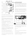
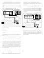
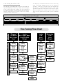
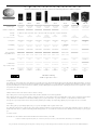
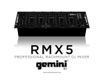
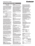
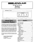
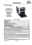
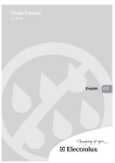
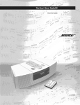
U s e r’
s
M odel
M anual
S W 10
P o w e re d
l
l
S W 12
S u b w o o fe r
IM PO R TAN T SAFETY IN STR U C TIO N S
C A U TIO N
R ISK O F ELEC TR IC SH O C K
D O N O T O PEN
C AU TIO N : TO R ED U C E R ISK O F ELEC TR IC AL SH O C K, D O N O T R EM O VE C O VER (O R BAC K). N O
U SER SER VIC EABLE PAR TS IN SID E. R EFER TO Q U ALIFIED SER VIC E PER SO N N EL.
The lightning flash w ith the arrow head sym bol,w ithin an equilateraltriangle,is intended to alertthe user to the presence ofuninsulated
“dangerous voltage” w ithin the product’s enclosure thatm ay be ofsufficientm agnitude to constitute a risk ofelectric shock to persons.
The exclam ation pointw ithin an equilateraltriangle is intended to alertthe user to the presence ofim portantoperating and m aintenance
(servicing) instructions in the literature accom panying the appliance.
W AR N IN G :TO R ED U C E TH E R ISK O F FIR E O R ELEC TR IC SH O C K,D O N O T EXPO SE TH IS APPLIAN C E TO R AIN O R M O ISTU R E.
1.R EAD IN STR U C TIO N S - Allsafety and operating instructions should be read before the appliance is operated.
2.R ETAIN IN STR U C TIO N S - Safety and operating instructions should be retained for future reference.
3.H EED W AR N IN G S - Allw arnings on the appliance and in operating instructions should be adhered to.
4.FO LLO W IN STR U C TIO N S - Alloperating and use instructions should be follow ed.
5.W ATER AN D M O ISTU R E-The appliance should notbe used nearw ater-nearbathtub,w ashbow l,kitchen sink,laundry tub;in a w etbasem ent near
a sw im m ing pool,etc.
6.C AR TS AN D STAN D S -D o notplace this producton an unstable cart,stand,tripod,bracket,ortable. The appliance should be used only w ith a cart
or stand thatis recom m ended by the m anufacturer.
7.VEN TILATIO N - The appliance should be situated so thatits location and position do notinterfere w ith proper ventilation. The appliance should not
be situated on a bed,sofa,rug,or any surface thatm ay obstructcabinetopenings.
8.H EAT -The appliance should be situated aw ay from heatsources such as radiators,heatregisters,stoves,orotherdevices (including am plifiers)that
produce heat.
9.PO W ER SO U R C ES - This productshould be operated only from the type ofpow er source indicated on the m arking label.Ifyou are notsure ofthe
type pow er supply in your hom e, consult your product dealer or localpow er com pany. For products intended to operate from battery pow er or other
sources,refer to the operating instructions.
10.PO W ER C O R D PR O TEC TIO N -Pow ersupply cords should be routed so thatthey are notlikely to be w alked upon orpinched by item s placed upon
or againstthem ,paying attention to cords and plugs,convenience receptacles,and the pointw here they exitfrom the appliance.
11.PO LAR IZED PLU G - This appliance is equipped w ith a polarized line plug (a plug having one blade w ider than the other).This plug w illfitinto the
pow er outletonly one w ay.This is a safety feature.Ifyou are unable to insertthe plug fully into the outlet,try reversing the plug.Ifthe plug stillfails to
fit,contactyour electrician to replace your obsolete outlet.D o notattem ptto defeatthis safety feature.
12.LIG H TN IN G -Foradded protection forthis productduring a lightning storm ,orw hen itis leftunattended and unused forlong periods oftim e,unplug
itfrom the w alloutletand disconnectthe antenna or cable system .This w illpreventdam age to the productdue to lightning and pow er line surges.
13.O VER LO AD IN G - D o notoverload w alloutlets,extension cords,or integralconvenience receptacles,as this can resultin a risk offire or electricshock.
14.C LEAN IN G -U nplug this productfrom the w alloutletbefore cleaning.D o notuse liquid cleaners oraerosolcleaners.U se a dam p cloth forcleaning.
15.N O N -U SE PER IO D S - This am plifier should be unplugged from the outletw hen the appliance is leftunused for a long period oftim e.
16.O BJEC T AN D LIQ U ID EN TR Y - N ever push objects ofany kind into this productthrough openings,as they m ay touch dangerous voltage points or
short-outparts thatcould resultin a fire or electric shock.N ever spillliquid ofany kind on this product.
17.D AM AG E R EQ U IR IN G SER VIC E - The appliance should be serviced by qualified personnelw hen:
a.The pow er supply cord or plug has been dam aged;or
b.O bjects have fallen on or liquid has been spilled into the appliance;or
c.The appliance has been exposed to rain;or
d.The appliance does notappear to operate norm ally or exhibits a m arked change in perform ance;or
e.The appliance has been dropped or the enclosure is dam aged.
18. SER VIC IN G - D o not attem pt to service this product yourself, as opening or rem oving covers m ay expose you to dangerous voltage or other
hazards.R efer allservicing to qualified service personnel.For service w arranty inform ation callthe N H T H otline num ber: 1-800-N H T-9993.
19.R EPLAC EM EN T PAR TS -W hen replacem entparts are required,be sure the service technician has used replacem entparts specified by the m anufacturer or thathave the sam e characteristics as the originalpart.U nauthorized substitution m ay resultin fire,electric shock,or other hazards.
20.SAFETY C H EC K - U pon com pletion ofany service or repairs to this product,ask the service technician to perform safety checks to determ ine that
the productis in proper operating condition.
C A U TIO N
TO PR EVEN T ELEC TR IC SH O C K,D O N O T U SE TH IS (PO LAR IZED )PLU G W ITH AN EXTEN SIO N C O R D ,
R EC EPTAC LE O R O TH ER O U TLET U N LESS TH E BLAD ES C AN BE FU LLY IN SER TED TO PR EVEN T
BLAD E EXPO SU R E.
Thank you for your purchase of the N H T
SW 10 llor SW 12 pow ered subw oofer.
Like all N H T loudspeakers, the SW 10 ll and SW 12's
developm ent has been guided by the study of hum an
hearing,it’s design rigorously tested,and its com ponents
optim ized to deliver clean,clear m usicalsound.
Since the quality of your speakers is one of the m ost
im portantfactors in m axim izing the sound you'llgetfrom
your m usic and hom e theater system , w e're sure that
you'll find your purchase of the SW 10 ll and SW 12 a
good investm ent,and invite your com m ents.
If you find your experience w ith the SW 10 lland SW 12
as satisfying as w e believe you w ill,and w ish to enjoy its
high quality sound through yourentire system ,you'llfind
inform ation about other sonically m atched N H T Super
Series loudspeakers on the back ofthis m anual.
B ackground
The N H T SW 10 lland SW 12 Pow ered Subw oofer is a
com pact, versatile and pow erful am plified subw oofer
designed to provide low frequency reinforcem entforhigh
perform ance audio and hom e theater system s.
The SW 10 lland SW 12 features:
• line-leveland speaker-levelinputs,for connection w ith
alltypes ofreceivers or other audio com ponents
• independentgain,phase and low pass filter controls
•boundary controlforadjusting system sound forvarious
room placem ent
Please take a few m inutes to read through this ow ner's
m anualbefore setting up yourspeakers;this inform ation
w illhelp you getthe m ostoutofthem . Also,please keep
the SW 10 ll or Sw 12’s packaging to use in case you
m ove or transportthem .
If you have questions at any tim e during setup or use,
feel free to call your N H T dealer or our Toll-Free
C ustom er H otline at1-800-N H T-9993.
Placem ent
N ote: To prevent the SW 10 ll and SW 12 subw oofer
am plifier from overheating, alw ays be sure to provide
adequate space for proper ventilation. D o not place the
subw oofer directly againstthe w allorany othersurface.
The key to placing yoursubw ooferforoptim alenjoym ent
is to rem em berthatlow frequencies produce sounds w ith
long w avelengths, w hich interact in com plex w ays w ith
room boundaries, such a w alls and corners, and other
large objects as w ell.
Placing the subw oofernearto a room boundary w illtend
to increase its apparent bass output, but m ay result in
"boom y"or"m uddy"sound. C onversely,placing itfarther
aw ay from room boundaries w ill tend to decrease its
apparent bass output, but m ay result in im proved
articulation and clarity.
W hen possible, place the subw oofer in the sam e
horizontal plane and along the sam e w all as the m ain
speakers.
And since sm allchanges in subw ooferposition can have
a significant effect on sound, experim enting w ith the
effects ofdifferentplacem ents in yourow n listening/view ing room is the key to finding the sound you like best.
SW 10 lland SW 12 Features & C ontrols
Volum e: This controlallow s you to adjustthe gain ofthe
Subw oofer relative to the restofyour system . M any listeners m ake the m istake ofsetting subw oofers too loud,
w hich can cause excess bloat and loss of detail and
m usicality.A properly calibrated subw ooferblends in w ith
the speakers and does not call attention to itself. To
properly setvolum e:
• Turn dow n the volum e controlon the SW 10 llor SW 12
to its low estposition (counter-clockw ise).
• Turn on your audio system , including the SW 10 ll or
SW 12. Play som e m usic you are fam iliar w ith and set
your receiver/pream plifier volum e to a com fortable listening level.
•Slow ly increase the volum e ofthe SW 10 llorSW 12,listening for proper frequency balance. W hen balanced,
you w illhearim proved bass extension,butnotbe aw are
thatitis com ing from the subw oofer.
From this point on, the volum e control on your
receiver/pream plifier w ill control the overall volum e of
your system ,including the subw oofer.
The B oundary EQ : This is a feature unique to N H T
Evolution products. R eflective boundaries (such as
w alls) reinforce a speaker’s bass output (3dB for tw o
w alls, 6dB for a corner) if the subw oofer is placed near
them . C onversely,placing a subw oofer outin the room
results in a relative decrease in bass output. Boundary
reinforcem ent m ay lead to low frequency response that
is uneven. Som e frequencies w ill sound exaggerated
relative to others, or the subw oofer w illsound thin and
lack im pact. The Boundary EQ control allow s you to
com pensate for the effects of room boundaries on the
frequency response
of the subw oofer. Adjusting the controlenables you to
achieve sm ooth low frequency output from the subw oofer regardless ofits location in your room .
The follow ing diagram s show n in Fig.1 show the correlation betw een subw oofer placem entand Boundary EQ .
These diagram s are guidelines only. Your room
acoustics and personaltastes w illultim ately dictate the
finalsetting.
Fig.1
Boundary
H alf
Space
+3dB
Tw o tips on using the Low Pass Filter:
As a starting point, set Low Pass Filter to the 1 o’clock
position.This w illresultin an 80H z low pass.As the setting is typicalfor m ost D olby D igital/ D TS applications.
N ote:The LFE inputbypasses the adjustable 12dB Low
Pass Filter.
See the Fine-Tuning section for further adjustm ent
guidelines.
SU B W O O FER PH A SE: This sw itch sets the phase of
the subw ooferateitherthe 0° position (norm alphase)or
the 180° position (reverse phase) to achieve the
sm oothestpossible bass response in your system .
This phase-reversing option is im portantbecause ifbass
frequencies com e from both the subw ooferand the m ain
speakers,peaks and dips in the frequency response can
occuratthe listening position. In these cases,reversing
the subw ooferphase can im prove blending and balance.
0
-3dB
To properly setthe Subw oofer Phase:
•Play fam iliarm usic,reversing phase settings.And listen
from your usualposition.
Q uarter/
H alf
Space
H alf/
W hole
Space
Boundary
+3dB
•Avoid evaluating w hile standing above the subw ooferor
am plifier; sound at the listening position w ill be
significantly different.
0
-3dB
Boundary
+3dB
0
-3dB
LO W PA SS FILTER :This controldeterm ines the upperlim it frequency the subw oofer w ill reproduce. For
exam ple, setting the filter at 100H z w ill cause the
subw oofer to reproduce only frequencies below 100H z.
The Low Pass Filter is continuously variable betw een
40H z (low bass) and 180H z (upper bass), to
accom m odate differentspeakers.
• The correctsetting is the one in w hich the bass is the
loudestatthe listening position.
PO W ER M O D E: This feature autom atically sw itches
your SW 10 ll or SW 12 into m inim um -pow er m ode (ie,
sleep) w henever no signal is present for 20 m inutes.
W hen a signalis received,itim m ediately turns on again.
As AU TO M ode is autom atic, it requires no adjustm ent,
nor is there a need to turn the SW 10 llor SW 12 on and
off every tim e it is used. W hen in O N M ode, the subw oofer is alw ays on.
9
8
7
4
C onnecting The SW 10IIO R SW 12
3
Line
Input
LFE
Low Pass
Filter
In
L
Out
R
40Hz
180Hz
Power
Mode
Hi Level Input
Volume
Max
Min
Phase Boundary
On
180
Auto
0
+3dB
5
0
+
L
-
-
R
-3dB
+
6
1
2
Green - On
Amber - Standby
Red - Protect
C aution: Before connecting the SW 10II O R SW 12 to
your audio system , it is im portant to unplug or turn off
all AC pow er connections to connected com ponents
such as receivers,am plifiers,pream plifiers,and processors. D o not plug in or connect the SW 10II O R SW 12
subw oofer to AC pow er untilallconnections have been
m ade.
On
Power
Powered
Subwoofer
10
Off
11
T3.0AL 250V
For 115 V
T2.0AL 250V
For 230V
Input Voltage
115
115V 60Hz /
230V 50Hz~
300W
CAUTION: FOR CONTINUED PROTECTION AGAINST
FIRE, REPLACE ONLY WITH SAME TYPE 250V FUSE
12
WARNING:
Integrating the SW 10IIor SW 12 into your surround system is sim ple and straightforw ard w hen using this connection m ethod. Your AV R eceiver w ill control all
crossoverfunctions and the SW 10IIorSW 12 w illcontrol
Subw oofer gain,phase and boundary equalization.
TO REDUCE THE RISK OF FIRE OR ELECTRIC
SHOCK, DO NOT EXPOSE THIS APPLIANCE TO RAIN OR MOISTURE.
CONFORMS TO
ULSTD.6500
CAUTION
RISK OF ELECTRIC SHOCK
DO NOT OPEN
CERTIFIED TO
CAN/CSA
STD.E60065
WARNING: SHOCK HAZARD-DO NOT OPEN.
AVIS: RISQUE DE CHOC ELECTRIQUE-NE PAS OUVRIR.
2001228
13
Back ofSubw oofer (referto diagram above)
C onnectthe Subw oofer/LFE O utputon yourAV R eceiver
to the LFE IN on the back ofthe SW 10IIor SW 12. (Fig.
2)
Main Speakers
(1) Pow er M ode - Leaves Subw oofer in perm anantly on
(O N ),or puts the subw oofer in autom atic standby m ode
(AU TO ).
Reciever
LFE / Sub
SPEAKER OUTPUTS
L
R
+
-
(2) Pow er Indicator - The light is green w hen the subw ooferis on.The lightis am berw hen the subw ooferis in
stand-by m ode.The lightis red w hen the subw ooferis in
protection.
SW10 / SW12
Back of Subwoofer
(3) Volum e C ontrol- Adjusts the loudness of the subw oofer independently ofthe m ain speakers.
Line
Input
LFE
Low Pass
Filter
In
(4) Low -Pass Filter - C ontinuously variable low -pass
crossover control.
Volume
L
Out
R
40Hz
180Hz
Power
Mode
Hi Level Input
Min
Max
Phase Boundary
On
180
Auto
0
+3dB
0
(5) B oundary Sw itch - Selects response m ode of subw oofer,depending on placem ent.
(6) Subw oofer Phase Selector - 2-position selectable
phase controlfor subw oofer.(0 - 180)
Fig.2
+
L
-
-
R
-3dB
+
(7)Line Input-Low levelR C A inputjacks forL/R signals
In the event your receiver or pre-am p does not have a
LFE or Subw oofer output the SW 10II/SW 12 has tw o
additionalconnection m ethods:
(8)LFE In/O ut-Low levelR C A inputjack forLFE orsubw oofer signal. O ut is an unbuffered pass through used
for m ultiple subw oofers.
1) Line Level
U se if:
(9) H iLevelInput- Speaker levelinputconnector.
(10) Pow er Sw itch -Turns the uniton and off
You have an am p or receiver w ith Pre-O ut jacks but no
LFE/Subw oofer jacks.
(11) Fuse H older - location ofthe user servicable fuse
(12)Pow er Inlet-ForuniversalAC line inputconnection
(13) Input Voltage Sw itch - Selects 115 VAC or 230
VAC m ains voltage.
To connect for a Line Level signal (Fig. 3), keep your
m ain speakers connected as usual, but use R C A linelevelcables to connectas follow s:
• Pream ps w ith Line O utjacks:connectone pair ofLine
O utcables to your m ain am p to pow er your m ain L & R
speakers, and a second pair to the SW 10II O R SW 12
LIN E LEVEL IN PU T. Ifyourpream p has only one pairof
Line O ut jacks, you can use a pair of "Y" connector
cords,available through your N H T dealer.
Main Speakers
Reciever
SPEAKER OUTPUTS
L
R
Pre Out
L
R
com ponent's speaker output term inals to the L & R
speakers, and a second pair from the sam e output term inals to the SW 10IIO R SW 12's H igh-Levelinput.The
SW 10IIO R SW 12's inputdoes notpresenta significant
load to the receiver,and w illnotcom prom ise its outputto
the L & R speakers. Ifyou find thatyourreceiverw illnot
accom m odate m ore than one cable per outputterm inal,
check w ith your N H T dealer for alternative m ethods of
connection.
+
-
Main Speakers
Reciever
SPEAKER OUTPUT
SPEAKER OUTPUT
LEFT
-
SW10 / SW12
Back of Subwoofer
Line
Input
LFE
Low Pass
Filter
In
L
Out
R
+
Volume
180Hz
Power
Mode
Fig.3
-
SW10 / SW12
Back of Subwoofer
40Hz
Hi Level Input
RIGHT
+
Min
Max
Phase Boundary
On
180
Auto
0
+3dB
0
+
L
-
-
R
-3dB
+
Line
Input
LFE
Low Pass
Filter
In
Out
ut
R
40Hz
• Am ps and receivers w ith Pre-O ut jacks: connect the
SW 10IIO R SW 12 from the Pre-O utinto the SW 10IIO R
SW 12's Line Input.
2) H i-Level
U se if:
Your receiver has no Pre O ut or Subw oofer/LFE O ut
jacks
To connectfora H igh-Levelsignal(Fig.4),use tw o additionalpairs ofspeaker cables,and connectas follow s:
• For am ps and receivers w ith separate A and B speakeroutputs,connectone pairofspeakercables from your
receiver's Speaker A outputs to your m ain L & R speakers, and a second pair from your receiver's Speaker B
outputs to the SW 10IIO R SW 12's H igh-LevelInput. U se
this m ethod only ifboth A & B speakeroutputs can operate sim ultaneously.
• For am ps and receivers w ith only one set of speaker
outputterm inals,sim ply feed the sam e signal,in parallel,
to both your m ain L & R speakers and the SW 10II O R
SW 12. C onnectone pair ofspeaker cables from your
Volume
L
180Hz
Power
Mode
Hi Level Input
Fig.4
Min
Max
Phase Boundary
On
180
Auto
0
+3dB
0
+
L
-
-
R
-3dB
+
W ith all signal connections com plete, it is now tim e to
apply AC pow er. Plug the pow er chord into the pow er
inletin the back ofthe subw oofer,plug the otherend into
into the w alloutlet and sw itch the subw oofers pow er to
the O N position.
The frequency chart below lists som e term s com m only
used to describe different bands of the frequency
spectrum . Listen to yoursystem and m ake adjustm ents
to achieve a seam less blend betw een your m ain
speakers and the SW 10 llorSW 12.Fourcom m on problem s are outlined below.Follow the flow chartto correct
these.See the glossary for any term s you are unfam iliar
w ith.
Fine Tuning the Subw oofer
The key to good subw oofer / speaker integration is
repeated listening, follow ed by m aking sm all re-adjustm ents of the subw oofer controls. The m ost im portant
bass tuning functions you w illcontrolare the LO W -PASS
FILTER , follow ed by the VO LU M E C O N TR O L settings
and then PH ASE SELEC TO R .
Frequency C hart
Low Bass
Below 50H z
M id Bass
U pper Bass
50H z-100H z
100H z-180H z
Low er M id
180H z-300H z
M id
300H z-700H z
U pper M id
H igh
700H z-3K
3K and above
Problem
"Boomy"
Too Much
Mid / Upper
Bass
Lacks
Mid / Upper Bass:
Lean But With
Weight
Solution
Fine Tuning Flow Chart
Adjust
Subwoofer
Phase
0-90
Adjust
Subwoofer
Phase
0-90
(Continuously
Add)
(Continuously
Add)
Lower
Low Pass
X-Over
Frequency
If this makes
it worse,
try
If the sound
improves
Lower
Subwoofer
Volume
Adjust
Subwoofer
Volume
Listen
Listen
Raise
Low-Pass
Setting
Adjust
Subwoofer
Volume
Adjust
Subwoofer
Phase
Listen
Lacks
Low
Bass
Weight
Excessive
Low
Bass
Weight
Adjust
Subwoofer
Phase
Switch
0-180
Decrease
Boundary
EQ
Increase
Boundary
EQ
Move
Subwoofer
Farther
From Wall
Listen
Move
Subwoofer
Closer to
Wall
Listen
O peration
W e recom m end thatthe SW 10 llor SW 12 pow er be left
on,w hich w illallow the built-in Auto M ode feature to disable the subw oofer w hen notin use.
Every speaker,has lim its,and it's im portantto listen for
them .Speaker dam age m ostoften results notfrom brief
loud m usicalpeaks,butfrom sustained high volum e levels in som e or all frequencies. For this
reason,
extrem e volum e settings and excessive bass, treble or
equalizer boosts are notrecom m ended.
Ifyou hear unusualdistortion or breakup,or notice heat
com ing from the w oofer, decrease volum e im m ediately,
neutralize any excess bass, treble or equalizer boosts,
and avoid setting any controls to sim ilarextrem es again.
M aintenance
YourSW 10 lland SW 12 is designed foryears ofuse w ith
no orm inim alm aintenance,as long as you avoid exposing it to direct sunlight, high tem peratures, or m oisture.
C lean cabinets,w hen necessary,using a dam p cloth or
a m ild, non-abrasive cleaner; to clean grilles, rem ove
from speaker and use a soft brush or a vacuum on its
low estsetting. D o notattem ptto clean the actualdriver.
9.8 C hanging the Line Voltage Setting
The SW 10 lland SW 12 w ere designed to operate on tw o
line voltage settings,115VAC and 230VAC . In the event
that it is necessary to change the line voltage setting,
begin by turning the pow er sw itch to the off position.
R em ove allthe connections from the am plifier,including
the detachable pow er cord. U sing a flat blade screw driver, slide the sw itch to the correct position. U se the
115VAC position for 110 to 120 VAC , and the 230VAC
position for 220 to 240 VAC . N extyou w illlikely need a
pow er cord thatfits the AC receptacle and you w illneed
to replace the fuse (see "C hanging the Fuse" below )
appropriate type.
• reinstallthe fuse holder
Alw ays replace the fuse w ith one of the exact sam e
specifications.
SW 10 ll:
Forsystem s operating at115 volts,use only a 5x20 m m ,
T3A,250-volt slow -blow fuse.
Forsystem s operating at230 volts,use only a 5x20 m m ,
T2.0A,250-volt slow -blow fuse.
SW 12:
Forsystem s operating at115 volts,use only a 5x20 m m ,
T5A,250-volt slow -blow fuse.
Forsystem s operating at230 volts,use only a 5x20 m m ,
T2.5A,250-volt slow -blow fuse.
Troubleshooting
If the SW 10 llor SW 12 fails to operate at allw hen the
Pow er Sw itch is turned on, thoroughly check the pow er
cord,inputand outputconnections
If the SW 10 llor SW 12 turns on but the LED indicator
fails to illum inate,m is-w iring ora pow ersurge m ay have
caused the protection fuse to blow.R eplace itw ith one of
correcttype and value.
Ifthe SW 10 llor SW 12 turns on butits status LED stays
red, the unit is gone into protect m ode, w hich could be
caused by incorrect w iring, short circuits, or excessive
volum e.Turn offthe Pow er Sw itch on the subw oofer for
tw o or m ore seconds to reset, and double check all
speakercables to be sure thatno sm allm etalstrands are
shorting the term inals.
Ifthese steps don'trestore the SW 10 llorSW 12 to operation, contactyourlocalAuthorized N H T D ealerorN H T
for assistance.
C hanging the Fuse
Satisfaction
The SW 10 lland SW 12 am plifier's fuse is user-serviceable.
To replace it:
• turn the pow er O FF
• unplug the pow er cord
•rem ove the fuse holdercover(above to the pow erinlet)
w ith a flatblade screw driver
• rem ove the fuse from the holderand replace itw ith the
Your satisfaction w ith your new N H T SW 10 llor SW 12
Subw oofer is im portantto us. Please note the m atched
products and accessories w e provide for them ,and your
w arranty,printed on the back ofthis m anual. Ifyou have
any questions regarding your speakers'use,feelfree to
callN H T at 1-800-N H T-9993. Enjoy your listening and
view ing!
G lossary
the back of a receiver, integrated am plifier or pow er
am plifier.
A ctive:U ses electricalpow er.
M idrange:The frequency span in the m iddle ofthe audio
A m plifier: An electronic device that increases the cur-
range, roughly 180H z - 3000H z. Also used to describe
rent and/or voltage of a signal, providing pow er to the
the driver thatreproduces these frequencies.
loudspeakers (i.e. pow er am plifier, integrated am plifier,
O hm :A unitofelectricalresistance.Thatw hich opposes
receiver).
an electric currentin a conductor. In audio,a m easure of
B ass: The range of audio frequencies below 180H z,
the load presented by a device to an electricalsource.
characterized by low pitch.
O ut-of-Phase: The polarity of an audio signal w hen
C rossover: An electronic circuit that divides an audio
connected as follow s:(+) to (-) and (-) to (+).
signalinto differentfrequency ranges.
Passive:U ses no electricalpow er.
D istortion:Any deviation from the originalsignal.
Phase:An expression ofthe relative polarities oftw o sig-
D river:The m oving partofa loudspeaker,w hich radiates
nals.
sound energy.
Pow er H andling:The ability ofa loudspeakerto operate
D ynam ics:Variations in loudness ofsound.
w ithout large increases in distortion w hen given varying
Frequency: A rate of vibration, w hich corresponds to
am ounts ofinputpow er.
m usicalpitch,expressed in H ertz (H z).
Pream plifier: An electronic device that selects sources
Full R ange: A signalencom passing the entire audible
and passes line-levelsignals to an am plifier.
frequency spectrum .
Pre-O ut:A pream p line-levelR C A outputon the back of
H ertz (H z):A unitequalto one cycle persecond,used to
a receiver,integrated am plifier or pream plifier.
m easure the frequency ofa signalor sound.
R eceiver: A pream plifier, am plifier and tuner built into
H igh-Pass Filter:A filter thatpasses only high frequen-
one chassis.
cies above a low er lim it.
Satellite:Front L & R speakers w hen used w ith a sub-
Im pedance:A m easure ofthe totalopposition to current
w oofer. Also referred to as "m ain speakers".
flow in an alternating currentcircuit,m easured in ohm s.
Sensitivity:A ratio ofvoltage across the speakerload to
In Phase:The polarity ofan audio signalw hen connect-
the acoustic pow er output,m easured in decibels.
ed as follow s:(+) to (+) and (-) to (-).
Sub O ut: An line level output for connection to a sub-
Integrated A m plifier: A pream plifier and am plifier built
w oofer or subw oofer signalprocessor.
into one chassis.
Subw oofer: A driver designed to operate over the low
InterconnectC able:A length ofshielded w ire w ith plugs
bass portion ofthe audio range. Also refers to a system
at both ends for feeding signals from one electronic
consisting ofa w ooferand its enclosure,w hich are phys-
device to another.
ically separate from the upper range loudspeakers.
L.F.E.:"Low Frequency Effects";The .1 channelofinfor-
Surround Speakers: Speakers located in the side or
m ation recorded on m ostm ultichanneldigitalsound for-
rear for surround channeleffects.
m ats.
Treble:The upper partofthe frequency spectrum ,con-
Line-Level C onnection: Low levelR C A/phono or XLR
sisting offrequencies above about3000H z.
type connection.
Tw eeter:A sm alldriver designed to reproduce high fre-
Load: A term used to describe the im pedance that a
quencies.
speaker presents to an am plifier.
W att:A m easure ofelectricalpow er,com bining the volt-
Low -Pass Filter: A filter that passes only low frequen-
age w ith the electricalcurrentrequired to drive the loud-
cies below a higher lim it.
speaker.
M ain Speakers: Front L & R channelspeakers, som e-
W eight:Low frequencies below 50H z.
tim es referred to as satellites.
W oofer:A driverdesigned to operate overthe bass por-
M ain-In:A line-levelR C A/XLR pow er am plifier inputon
tion ofthe audio range.
S
p
e c i f i c a t i o
n
s
AllSuper Series products are sonically m atched for seam less integration into m ultichannelsystem s.
S uper S eri
es
SB 1
System Type
2-W ay Acoustic
Suspension
SB 2
2-W ay Acoustic
Suspension
SB 3
2-W ay Acoustic
Suspension
ST4
3-W ay Acoustic
Suspension
SC 1
SC 2
2-W ay Acoustic
Suspension
2-W ay Acoustic
Suspension
SW 10
SW 12
Vented /
Pow ered - 150 w atts
C lass G Am plifier
Vented /
Pow ered - 250 w atts
C lass G Am plifier
10”
Alum inum
(N otVideo Shielded)
12”
Alum inum
(N otVideo Shielded)
D river C om plem ent
Tw eeter-
1” fluid cooled alum inum dom e tw eeter w ith neodym ium m agnet structure
W oofer-
5.25”
Polypropylene
6.5”
Polypropylene
6.5”
Polypropylene
Video Shielded U nless N oted
6.5” and 8”
Polypropylene
(2) 4.5”
Polypropylene
(2) 5.25”
Polypropylene
(8” N otVideo Shielded)
R esponse
Sensitivity
Im pedance
R ecom m ended
A m plifier Pow er
68H z - 22kH z
+/- 3dB
51H z - 22kH z
+/- 3dB
39H z - 22kH z
+/- 3dB
31H z - 22kH z
+/- 3dB
78H z - 22kH z
+/- 3dB
73H z - 22kH z
+/- 3dB
86dB /2.83v
86dB /2.83v
86dB /2.83v
86dB /2.83v
86dB /2.83v
87dB /2.83v
8 ohm nom inal
8 ohm nom inal
8 ohm nom inal
8 ohm nom inal
8 ohm nom inal
8 ohm nom inal
31H z - 180H z
+/- 3dB
27H z - 180H z
+/- 3dB
M inim um 15 w atts
M inim um 15 w atts
M inim um 15 w atts
M inim um 15 w atts
M inim um 15 w atts
M inim um 15 w atts
M axim um 125 w atts
M axim um 150 w atts
M axim um 175 w atts
M axim um 200 w atts
M axim um 150 w atts
M axim um 175 w atts
8 lbs.
13 lbs.
16 lbs.
47.5 lbs.
11 lbs.
22 lbs.
39.5 lbs.
47.5 lbs.
6.75 x 6.25 x 10.25
8.75 x 7.5 x 11.85
10 x 8 x 13
12 x 8 x 38
6.63 x 16.54 x 5.63
8.5 x 19 x 6.5
14 x 12 x 18
16 x 14 x 20
W hite or Black
H igh G loss Piano
Finish
W hite or Black
H igh G loss Piano
Finish
Black
H igh G loss Piano
Finish
Black
H igh G loss Piano
Finish
Black
H igh G loss Piano
Finish
Black
H igh G loss Piano
Finish
Black
H igh G loss Piano
Finish
Black
H igh G loss Piano
Finish
W eight
D im ensions
D epth” x W idth” x H eight”
Finish
Lim ited W arranty
Valid O nly in the U .S.A .
W arranty Period
Fora period of5 years forparts and 5 years forlabor(1 yearparts and 90 days laborforelectronics)from the date this productis firstpurchased from an authorized N H T dealer,N ow H earThis (N H T)w arrants thatifitfails to function properly due to a m anufacturing defect,despite its being installed and operated according to these instructions and used under norm alconditions,itw illbe either replaced or repaired w ith new or rebuiltparts (both atN H T's option) w ith a unitof
com parable value w ithoutcharge to you.
W hat's N ot C overed
A ltered,defaced or rem oved serialnum bers void this w arranty.
This w arranty does notcover any productused in trade,business,industrialor com m ercialapplications.
This w arranty also does not cover the cabinet or appearance factors, or costs, defects or dam age resulting from m isuse, abuse, accident, im proper m aintenance,alterations or m odifications notauthorized in w riting by N H T,or parts or labor from any source other than an authorized N H T service location.
D am age due to pow er exposure in excess ofthe speaker's published pow er ratings;ie,overpow ering,lightning or pow er surges,are also notcovered.
Your R ights
This w arranty gives you specific legalrights,and you m ay have other rights w hich vary from state to state.
N H T lim its this w arranty to the purchase price ofthe product,excludes incidentalor consequentialdam ages,and lim its its obligations under any im plied w arranties under state law s to a period notexceeding their w arranty periods. As som e states do notallow the above lim itations,how ever,they m ay notapply to
you.
To O btain Service
To find the nam e and address ofthe nearestauthorized N H T service location,callor w rite:
C ustom er Service D epartm ent,N H T,527 Stone R d.,B enicia,C A 94510,1-800-N H T-9993 (648-9993),w w w .nhthifi.com
For your future convenience,please keep this w arranty w ith your sales receipt,and record date and place of purchase for further reference.