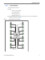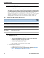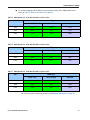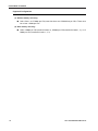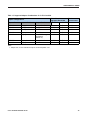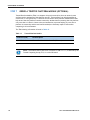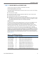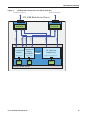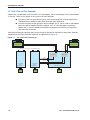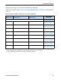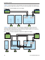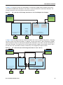
1
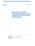
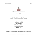
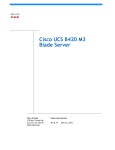
Cisco UCS B420 M4
Blade Server
CISCO SYSTEMS
170 WEST TASMAN DR.
SAN JOSE, CA, 95134
WWW.CISCO.COM
PUBLICATION HISTORY
REV A.2
JUNE 17, 2015
CONTENTS
OVERVIEW . . . . . . . . . . . . . . . . . . . . . . . . . . . . . . . . . . . . . . . . . . . . . . . 3
DETAILED VIEWS . . . . . . . . . . . . . . . . . . . . . . . . . . . . . . . . . . . . . . . . . . . 4
Blade Server Front View . . . . . . . . . . . . . . . . . . . . . . . . . . . . . . . . . . . . . . . . . . . . . . .4
BASE SERVER STANDARD CAPABILITIES and FEATURES . . . . . . . . . . . . . . . . . 5
CONFIGURING the SERVER . . . . . . . . . . . . . . . . . . . . . . . . . . . . . . . . . . . . 7
STEP
STEP
STEP
STEP
STEP
STEP
STEP
STEP
STEP
STEP
STEP
STEP
STEP
1 VERIFY SERVER SKU . . . . . . . . . . . . . . . . . . . . . . . . . . . . . . . . . . . . . . . . . . . . 8
2 CHOOSE CPU(S) . . . . . . . . . . . . . . . . . . . . . . . . . . . . . . . . . . . . . . . . . . . . . . 9
3 CHOOSE MEMORY . . . . . . . . . . . . . . . . . . . . . . . . . . . . . . . . . . . . . . . . . . . . 11
4 CHOOSE RAID CONTROLLER AND DISK DRIVE BAYS . . . . . . . . . . . . . . . . . . . . . . . 15
5 CHOOSE HARD DISK DRIVES or SOLID-STATE DRIVES (OPTIONAL) . . . . . . . . . . . . . . 18
6 CHOOSE ADAPTERS . . . . . . . . . . . . . . . . . . . . . . . . . . . . . . . . . . . . . . . . . . . 20
7 ORDER A TRUSTED PLATFORM MODULE (OPTIONAL) . . . . . . . . . . . . . . . . . . . . . . 24
8 ORDER CISCO FLEXIBLE FLASH SECURE DIGITAL CARDS . . . . . . . . . . . . . . . . . . . . 25
9 ORDER INTERNAL USB 2.0 DRIVE (OPTIONAL) . . . . . . . . . . . . . . . . . . . . . . . . . . 26
10 CHOOSE OPERATING SYSTEM AND VALUE-ADDED SOFTWARE . . . . . . . . . . . . . . . 27
11 CHOOSE OPERATING SYSTEM MEDIA KIT (OPTIONAL) . . . . . . . . . . . . . . . . . . . . 30
12 CHOOSE SERVICE and SUPPORT LEVEL . . . . . . . . . . . . . . . . . . . . . . . . . . . . . . 31
13 CHOOSE LOCAL KVM I/O CABLE* (OPTIONAL) . . . . . . . . . . . . . . . . . . . . . . . . . 36
SUPPLEMENTAL MATERIAL . . . . . . . . . . . . . . . . . . . . . . . . . . . . . . . . . . . 37
System Board . . . . . . . . . . . . . . . . . . . . . . . . . . . . . . . . .
DIMM and CPU Layout . . . . . . . . . . . . . . . . . . . . . . . . . . . .
DIMM Population Order . . . . . . . . . . . . . . . . . . . . . . . . . . .
Network Connectivity . . . . . . . . . . . . . . . . . . . . . . . . . . . .
VIC 1340/1240 and Port Expander . . . . . . . . . . . . . . . .
Connectivity Using the Cisco UCS 2208XP Fabric Extender
Connectivity using the Cisco UCS 2204XP Fabric Extender
. . . . . . . . . . . . . . . . . . . . 37
. . . . . . . . . . . . . . . . . . . . 39
. . . . . . . . . . . . . . . . . . . . 40
. . . . . . . . . . . . . . . . . . . . 44
. . . . . . . . . . . . . . . . . . . . 46
. . . . . . . . . . . . . . . . . . . . 47
. . . . . . . . . . . . . . . . . . . . 53
TECHNICAL SPECIFICATIONS . . . . . . . . . . . . . . . . . . . . . . . . . . . . . . . . . . 58
Dimensions and Weight . . . . . . . . . . . . . . . . . . . . . . . . . . . . . . . . . . . . . . . . . . . . . . . 58
Power Specifications . . . . . . . . . . . . . . . . . . . . . . . . . . . . . . . . . . . . . . . . . . . . . . . . 58
2
Cisco UCS B420 M4 Blade Server
OVERVIEW
OVERVIEW
Designed for demanding virtualization and database workloads, the UCS B420 M4 combines a large memory
footprint with four-socket scalability, leveraging the Intel® Xeon® processor E5-4600 v3 product family. The
UCS B420 M4 supports 2133 MHz DDR4 memory and utilizes UCS Virtual Interface Card (VIC) technology to
achieve up to 160 Gb aggregate I/O bandwidth, all in a dense, full-width blade form factor. The UCS B420
M4 maintains memory performance even as capacity grows, and the large power envelope of the UCS 5108
Blade Server Chassis means the UCS B420 can handle up to 3 TB of memory without compromise to CPU
speed or core count. Up to four UCS B420 M4 Blade Servers can be installed in the UCS 5108 Blade Server
Chassis.
The UCS B420 M4 Blade Server is centrally managed using Cisco UCS Manager. Cisco UCSM provides a single
management interface for all hardware and software components of a UCS domain. Cisco UCSM manages up
to 160 servers, using Single Connect Technology to consolidate network, storage, and management traffic.
With Cisco UCS Central, management can be extended globally to thousands of servers in multiple domains.
Figure 1
Cisco UCS B420 M4 Blade Server
Cisco UCS B420 M4 Blade Server
3
DETAILED VIEWS
DETAILED VIEWS
Blade Server Front View
Figure 2 is a detailed front view of the Cisco UCS B420 M4 Blade Server.
Figure 2
Blade Server Front View
2
3
4
305013
1
14
9
14
5
6
7
8
12
10 11
1
Drive bay 1
8
Power button and LED
2
Drive bay 2
9
Network link status button
3
Drive bay 3
10
Blade health LED
4
Drive bay 4
11
Local console connector1
5
Left blade ejector handle
12
Reset button access
6
Asset pull handle
13
Beaconing LED and button
14
Ejector thumbscrew
13
(a blank asset tag is provided on which
you can add your own label or sticker or
you can use a marker to write your asset
information on the tag)
7
Right blade ejector handle
Notes
1. For information about the KVM local I/O cable that plugs into the console connector (a cable is included with
every Cisco UCS 5100 Series blade server chassis accessory kit), see CHOOSE LOCAL KVM I/O CABLE*
(OPTIONAL) on page 36.
4
Cisco UCS B420 M4 Blade Server
BASE SERVER STANDARD CAPABILITIES and FEATURES
BASE SERVER STANDARD CAPABILITIES and FEATURES
Table 1 lists the capabilities and features of the base server. Details about how to configure the server for
a particular feature or capability (for example, number of processors, disk drives, or amount of memory)
are provided in CONFIGURING the SERVER on page 7.
NOTE: The B420 M4 blade server requires UCS Manager (UCSM) to operate as part of
the UCS system.
■
The B420 M4 with E5-4600 v3 CPUs requires UCSM 2.2(5a) or later
Table 1 Capabilities and Features
Capability/Feature
Description
Blade server chassis
The full-width UCS B420 M4 Blade Server mounts in a Cisco UCS 5100 series
blade server chassis
CPU
Up to four Intel® E5-4600 v3 series processor family CPUs.
2- and 4-CPU configurations are supported on the UCS B420 M4.
Chipset
Intel® C610 chipset
Memory
48 total slots for registered ECC DIMMs
I/O
3 configurable adapter slots:
Storage controller
■
One slot supports the Cisco VIC 1340/1240 adapter only.
■
Two additional slots support Cisco adapters and Cisco UCS Storage
Accelerator adapters.
■
Diskless system (no drive bays or RAID controller), or
■
Optional Cisco FlexStorage 12G SAS RAID controller options, offering:
• SAS/SATA/HDD/SSD support
• RAID support: 0, 1, 10
Storage devices
Either two or four hot-plug 2.5” SFF drive bays
One internal USB 2.0 port
Two Cisco Flexible Flash secure digital card slots
Interfaces
Front panel
■
Cisco UCS B420 M4 Blade Server
One console connector
(see CHOOSE LOCAL KVM I/O CABLE* (OPTIONAL) on page 36)
5
BASE SERVER STANDARD CAPABILITIES and FEATURES
Table 1 Capabilities and Features (continued)
Capability/Feature
Video
Description
The Cisco Integrated Management Controller (CIMC) provides video using the
Matrox G200e video/graphics controller:
■
■
Integrated 2D graphics core with hardware acceleration
DDR2/3 memory interface supports up to 512 MB of addressable memory
(8 MB is allocated by default to video memory)
■
Supports display resolutions up to 1920 x 1200 16bpp @ 60Hz
■
High-speed integrated 24-bit RAMDAC
■
Single lane PCI-Express host interface running at Gen 1 speed
Power subsystem
Integrated in the Cisco UCS 5100 series blade server chassis
Fans
Integrated in the Cisco UCS 5100 series blade server chassis
Integrated management
processor
The built-in Cisco Integrated Management Controller (CIMC) GUI or CLI
interface enables you to monitor the server inventory, health, and system
event logs.
Cisco UCS Diagnostics
for Cisco UCS B-Series
Blade Servers
The Cisco UCS Blade Server Diagnostics tool for Cisco UCS Blade Servers
enables you to verify the health of the hardware components on your
servers. The diagnostics tool provides a variety of tests to exercise and
stress the various hardware subsystems on the Cisco UCS Blade Servers, such
as memory and CPU. You can use the tool to run a sanity check on the state
of your Cisco UCS Blade Servers after you fix or replace a hardware
component. You can also use this tool to run comprehensive burn-in tests
before you deploy a new Cisco UCS Blade Server in your production
environment.
See the following links for more information:
User Guide:
http://www.cisco.com/c/en/us/td/docs/unified_computing/ucs/sw/ucs_di
agnostics/b_UCS_Blade_Server_Diagnostics_User_Guide.html
ISO Download:
http://www.cisco.com/cisco/software/navigator.html
6
Cisco UCS B420 M4 Blade Server
CONFIGURING the SERVER
CONFIGURING the SERVER
Follow these steps to configure the Cisco UCS B420 M4 Blade Server:
■
STEP 1 VERIFY SERVER SKU, page 8
■
STEP 2 CHOOSE CPU(S), page 9
■
STEP 3 CHOOSE MEMORY, page 11
■
STEP 5 CHOOSE HARD DISK DRIVES or SOLID-STATE DRIVES (OPTIONAL), page 18
■
STEP 6 CHOOSE ADAPTERS, page 20
■
STEP 7 ORDER A TRUSTED PLATFORM MODULE (OPTIONAL), page 24
■
STEP 8 ORDER CISCO FLEXIBLE FLASH SECURE DIGITAL CARDS, page 25
■
STEP 9 ORDER INTERNAL USB 2.0 DRIVE (OPTIONAL), page 26
■
STEP 10 CHOOSE OPERATING SYSTEM AND VALUE-ADDED SOFTWARE, page 27
■
STEP 11 CHOOSE OPERATING SYSTEM MEDIA KIT (OPTIONAL), page 30
■
STEP 12 CHOOSE SERVICE and SUPPORT LEVEL, page 31
■
STEP 13 CHOOSE LOCAL KVM I/O CABLE* (OPTIONAL), page 36
Cisco UCS B420 M4 Blade Server
7
CONFIGURING the SERVER
STEP 1
VERIFY SERVER SKU
Verify the product ID (PID) of the server as shown in Table 2.
Table 2 PID of the Base UCS B420 M4 Blade Server
Product ID (PID)
UCSB-B420-M4
Description
UCS B420 M4 Blade Server with no CPU, memory, HDD, SSD, or adapter cards
The base Cisco UCS B420 M4 blade server does not include the following components. They must
be selected during product ordering:
■
CPUs
■
Memory
■
Disk drives
■
Cisco adapters (such as the VIC 1340, VIC 1240, VIC 1380, VIC 1280, and Port Expander)
■
Cisco UCS Storage Accelerators
NOTE: Use the steps on the following pages to order servers with the
configurable components that you want configured in your servers.
8
Cisco UCS B420 M4 Blade Server
CONFIGURING the SERVER
STEP 2
CHOOSE CPU(S)
The standard CPU features are:
■
Intel Xeon processor E5-4600 v3 series processor family CPUs
■
Core counts of up to 18
■
Cache sizes of up to 45 MB
Select CPUs
The supported Intel Xeon E5-4600 v3 series CPUs on the UCS B420 M4 are listed in Table 3.
Table 3 Supported Intel CPUs: E5-4600 v3 Series Processor Family CPUs
Product ID (PID)
Intel
Number
Clock
Freq
(GHz)
Power
(W)
Cache
Cores
Size (MB)
QPI
Highest DDR4 DIMM
Clock Support (MHz)
Intel Xeon E5-4600 v3
UCS-CPU-E5-4669D
E5-4669 v3
2.10
135
45
18
9.6
2133
UCS-CPU-E5-4667D
E5-4667 v3
2.00
135
40
16
9.6
2133
UCS-CPU-E5-4660D
E5-4660 v3
2.10
120
35
14
9.6
2133
UCS-CPU-E5-4655D
E5-4655 v3
2.90
135
30
6
9.6
2133
UCS-CPU-E5-4650D
E5-4650 v3
2.10
105
30
12
9.6
2133
UCS-CPU-E5-4640D
E5-4640 v3
1.90
105
30
12
8.0
1866
UCS-CPU-E5-4627D
E5-4627 v3
2.60
135
25
10
8.0
2133
UCS-CPU-E5-4620D
E5-4620 v3
2.00
105
25
10
8.0
1866
UCS-CPU-E5-4610D
E5-4610 v3
1.70
105
25
10
6.4
1600
Cisco UCS B420 M4 Blade Server
9
CONFIGURING the SERVER
Supported Configurations
(1) Two-CPU Configuration
■
Choose two identical CPUs from any one of the rows of Table 3. CPUs 1 and 2 will be
populated.
(2) Four-CPU Configuration
■
Choose four identical CPUs from any one of the rows of Table 3.
■
The system will run at the lowest CPU or DIMM clock speed.
■
System speed is also dependent on how many DIMMs are populated per channel.
■
For 2-CPU systems, only 24 DIMM slots are functional (channels A - H).
■
See Table 11 on page 22 for supported adapter combinations in 2-CPU systems.
■
For 4-CPU systems, all 48 DIMM slots are functional.
Notes
10
Cisco UCS B420 M4 Blade Server
CONFIGURING the SERVER
STEP 3
CHOOSE MEMORY
The standard memory features are:
DDR4 ECC registered DIMMs
—
Clock speed: 2133 MHz
—
Ranks per DIMM: up to 8
—
Operational voltage: 1.2 V
Memory is organized with four memory channels per CPU, with up to three DIMMs per
channel (DPC), as shown in Figure 3.
Bank 2
Bank 3
Bank 1
UCS B420 M4 Memory Organization
Bank 3
Figure 3
—
E1 E2 E3
A3 A2 A1
Channel A
Channel E
Channel B
Channel F
Channel C
Channel G
Channel D
Channel H
B3 B2 B1
F1 F2 F3
G1 G2 G3
C3 C2 C1
D3 D2 D1
H1 H2 H3
CPU 2
CPU 3
CPU 4 Channel M
Bank 1
Bank 3
Bank 2
Bank 1
CPU 1
I3 I2 I1
Bank 2
Bank 3
■
DIMMs
Bank 2
Bank 1
■
M1 M2 M3
Channel I
J3 J2 J1
N1 N2 N3
Channel J
Channel N
K3 K2 K1
O1 O2 O3
Channel K
Channel O
I3 I2 I1
P1 P2 P3
Channel L
Channel P
48 DIMMS
4 memory channels per CPU
3 DIMMs per channel
Cisco UCS B420 M4 Blade Server
11
CONFIGURING the SERVER
Choose DIMMs and Memory Mirroring
Select the memory configuration and whether or not you want the memory mirroring option.
The supported memory DIMMs and the mirroring option are listed in Table 4.
When memory mirroring is enabled, the memory subsystem simultaneously writes identical data
to two adjacent channels. If a memory read from one of the channels returns incorrect data due
to an uncorrectable memory error, the system automatically retrieves the data from the other
channel. A transient or soft error in one channel does not affect the mirrored data, and
operation continues unless there is a simultaneous error in exactly the same location on a DIMM
and its mirrored DIMM. Memory mirroring reduces the amount of memory available to the
operating system by 50% because only one of the two populated channels provides data.
Table 4 Supported DDR4 DIMMs and Memory Mirroring Option
PID Description
Voltage
Ranks
/DIMM
UCS-MR-1X648RU-A
64GB DDR4-2133-MHz TSV-RDIMM/PC4-17000/x4
1.2 V
8
UCS-MR-1X322RU-A
32GB DDR4-2133-MHz RDIMM/PC4-17000/x4
1.2 V
2
UCS-MR-1X162RU-A
16GB DDR4-2133-MHz RDIMM/PC4-17000/x4
1.2 V
2
UCS-MR-1X081RU-A
8GB DDR4-2133-MHz RDIMM/PC4-17000/x4
1.2 V
1
Product ID (PID)
DIMM Options
Memory Mirroring Option
N01-MMIRROR
Memory mirroring option
Notes
■
■
12
DIMM configuration rules:
—
The minimum configuration is 1 DIMM per CPU
—
The order in which DIMMs must be installed in a channel is Bank 1 (blue socket),
then Bank 2 (black socket), then Bank 3 (white socket).
—
You cannot mix DIMM capacities within a bank
—
You can mix DIMM capacities within a channel
—
64GB TSV-RDIMMs cannot be mixed with any other DIMMs
To optimize memory performance:
—
Configure DIMMs identically for each CPU
—
Fill banks equally across the CPU. See DIMM population guidelines in Table 25 on
page 40, Table 26 on page 41, and Table 27 on page 41.
—
Populate less than 3 DPC
Cisco UCS B420 M4 Blade Server
CONFIGURING the SERVER
■
For systems shipping with E5-4600 v3 series processor family CPUs, DIMM speeds are as
shown in Table 5, Table 6, and Table 7 on page 13.
Table 5 DIMM Speeds for 2133-MHz E5-4600 v3 Series CPUs
DPC
DIMM Type
64 GB (TSV)
16/32 GB (DR)
8 GB (SR)
1DPC
2133
2133
2133
2DPC
2133
2133
2133
3 DPC
1600
1866
1600
Table 6 DIMM Speeds for 1866-MHz E5-4600 v3 Series CPUs
DPC
DIMM Type
64 GB (TSV)
16/32 GB (DR)
8 GB (SR)
1DPC
1866
1866
1866
2DPC
1866
1866
1866
3 DPC
1333
1600
1333
Table 7 DIMM Speeds for 1600-MHz E5-4600 v3 Series CPUs
DPC
DIMM Type
64 GB (TSV)
16/32 GB (DR)
8 GB (SR)
1DPC
1600
1600
1600
2DPC
1600
1600
1600
3 DPC
1066
1333
1066
For more information regarding memory, see DIMM and CPU Layout on page 39.
Cisco UCS B420 M4 Blade Server
13
CONFIGURING the SERVER
Supported Configurations
(1) Without memory mirroring:
■
Select from 1 to 12 DIMMs per CPU (note that there are 12 DIMM slots per CPU). There must
be at least 1 DIMM per CPU.
(2) With memory mirroring:
■
14
Select 4 DIMMs per CPU (installed in bank 1), 8 DIMMs per CPU (installed in banks 1, 2), or 12
DIMMs per CPU (installed in banks 1, 2, 3).
Cisco UCS B420 M4 Blade Server
CONFIGURING the SERVER
STEP 4
CHOOSE RAID CONTROLLER AND DISK DRIVE BAYS
The UCS B420 M4 can be ordered with or without the Cisco FlexStorage RAID controller with disk
drive bays (local storage subsystem).
There is no RAID or local storage controller or drive bays included (embedded) with the B420 M4
server. Therefore, the Cisco FlexStorage RAID controller with drive bays must be purchased in
order to support any (1, 2, 3, or 4) local hard disk drives (HDDs) or solid state drives (SSDs). The
Cisco FlexStorage RAID controller option includes drive bays one and two, and supports RAID
0,1,10. An optional passthrough module includes drive bays three and four.
For servers that do not need any local HDDs or SSDs (for example, for booting from SAN), you can
order the server without the Cisco FlexStorage RAID controller with disk drive bays; however be
sure to keep Cisco FlexStorage blanking panels installed to maintain proper cooling airflow.
The ordering information is listed in Table 10.
Table 8 Card Cage and RAID Ordering Options
Product ID (PID)
PID Description
UCSB-MRAID12G
Cisco FlexStorage 12G SAS RAID controller with two drive bays
UCSB-LSTOR-PT
Passthrough module with two drive bays
UCSB-LSTOR-BK
Cisco FlexStorage blanking panels w/o controller, w/o drive bays
See Figure 4 on page 16 for a top view of the B420 M4 server with and without the Cisco
FlexStorage SAS RAID controller and drive bays. See Figure 5 on page 16 for a front view of
these configurations. When no drive bays are installed, blanking panels must be installed.
Cisco UCS B420 M4 Blade Server
15
CONFIGURING the SERVER
Figure 4
UCS B420 M4 With and Without Drive Bays (Top View)
RAID
Controller
(integrated
in drive bay)
Disk Drive
Bays (4)
Blanking Panels
(a) Server with four drive bays
Figure 5
(b) Server with no drive bays
UCS B420 M4 With and Without Drive Bays (Front View)
Blanking Panels
(a) Server with four drive bays
(b) Server with no drive bays
Blanking Panel
16
Cisco UCS B420 M4 Blade Server
CONFIGURING the SERVER
Supported Configurations1
(1) Four Drive Bays with RAID 0, 1, 10
■
Choose the following:
—
One UCSB-MRAID12G. This provides two drive bays installed on the left side of the
blade server (viewed from the front). The RAID controller is integrated in the drive
bays and provides RAID 0,1,10.
—
One UCSB-LSTOR-PT. This provides two drive bays installed on the right side of the
blade server (viewed from the front) and includes a passthrough connector that
allows the drives to be managed from the RAID controller in UCSB-MRAID12G (RAID
0,1,10).
(2) Two Drive Bays with RAID 0, 1, 10
■
Choose the following:
—
One UCSB-MRAID12G. This provides two drive bays installed on the left side of the
blade server (viewed from the front). The RAID controller is integrated in the drive
bays and provides RAID 0,1,10. The two right-hand bays are fitted with blanking
panels to maintain proper cooling airflow.
(3) No Drive Bays
■
System is installed with blanking panels.
Notes
1. Any empty drive bays must be fitted with blanking panels to maintain proper cooling airflow.
Cisco UCS B420 M4 Blade Server
17
CONFIGURING the SERVER
STEP 5
CHOOSE HARD DISK DRIVES or SOLID-STATE DRIVES (OPTIONAL)
The UCS B420 M4 can be ordered with or without drives. If you ordered one of the RAID
controller with drive bay options in CHOOSE RAID CONTROLLER AND DISK DRIVE BAYS on page
15 (UCSB-MRAID12G for drive bays one and two, and optionally UCSB-LSTOR-PT for drive bays
three and four), you can order drives listed in this section. The B420 M4 provides up to four hot
plug 2.5” SFF drive bays.
Choose Drives
The supported drives in the UCS B420 M4 are listed in Table 9.
Table 9 Supported Hot Plug Drives
PID Description
Drive
Type
Capacity
UCS-HD12T10KS2-E
1.2 TB SAS 10K RPM SFF HDD
SAS
1.2 TB
A03-D600GA2
600 GB SAS 10K RPM SFF HDD
SAS
600 GB
UCS-HD450G15KS2-E
450 GB SAS 15K RPM SFF HDD
SAS
450 GB
UCS-HD300G12F105
300 GB 6 Gb SAS 15K RPM SFF HDD
SAS
300 GB
A03-D300GA2
300 GB SAS 10K RPM SFF HDD
SAS
300 GB
UCS-SD16T12S2-EP
1.6 TB 2.5 inch Enterprise performance 12G SAS SSD
SAS
1.6 TB
UCS-SD400G12S2-EP
400 GB 2.5 inch Enterprise performance 12G SAS SSD
SAS
400 GB
UCS-SD480G0KS2-EV
480 GB 2.5 inch Enterprise Value 6G SATA SSD
SATA
480 GB
UCS-SD120G0KS2-EV
120 GB 2.5 inch Enterprise Value 6G SATA SSD
SATA
120 GB
Product ID (PID)
HDDs
SSDs
18
Cisco UCS B420 M4 Blade Server
CONFIGURING the SERVER
Supported Configurations
■
Select up to 4 of the drives listed in Table 9. This is dependent on the number of drive bays
selected in CHOOSE RAID CONTROLLER AND DISK DRIVE BAYS on page 15.
■
When creating a RAID volume, mixing different capacity drives causes the system to use the
lowest-capacity drive.
■
Mixing of drive types is supported, but performance may be impacted.
■
Multiple RAID volumes are supported. RAID volumes should use the same media type.
Notes
Cisco UCS B420 M4 Blade Server
19
CONFIGURING the SERVER
STEP 6
CHOOSE ADAPTERS
The adapter offerings are:
■
Cisco Virtual Interface Cards (VICs)
Cisco developed 1300 Series and 1200 Series Virtual Interface Cards (VICs) to provide flexibility
to create multiple NIC and HBA devices. The VICs also support adapter Fabric Extender and
Virtual Machine Fabric Extender technologies. The VIC features are listed here:
—
1200 Series VICs enable advanced networking features including Netflow for
network statistics, and DPDK, USNIC for low-latency computing applications.
—
1300 Series VICs include all of the 1200 Series features plus additional
enhancements including network overlay offload support for NVGRE and VXLAN, and
RoCE services.
—
In addition, 1300 Series VICs support PCIe Gen 3.0 for greater bandwidth than 1200
Series VICs
—
Two Converged Network Adapter (CNA) ports, supporting both Ethernet and FCoE
—
Delivers 160 Gbs total I/O throughput to the server, for example:
• VIC 1240 supports 4 x 10 Gbs Unified I/O ports, Port Expander supports 4 x 10 Gbs
Unified I/O ports, and VIC 1280 supports 8 x 10 Gbs Unified ports, for a total of
160 Gbs (see Figure 16 on page 50).
• VIC 1340 supports dual 4 x 10 Gbs Unified I/O ports, Port Expander supports 4 x
10 Gbs Unified I/O ports, and VIC 1380 supports 8 x 10 Gbs Unified ports, for a
total of 160 Gbs (see Figure 16 on page 50).
■
—
Creates up to 256 fully functional unique and independent PCIe adapters and
interfaces (NICs or HBAs) without requiring single-root I/O virtualization (SR-IOV)
support from operating systems or hypervisors
—
Provides virtual machine visibility from the physical network and a consistent
network operations model for physical and virtual servers
—
Supports customer requirements for a wide range of operating systems and
hypervisors
Cisco UCS Storage Accelerator Adapters
Cisco UCS Storage Accelerator adapters are designed specifically for the Cisco UCS B-series M4
blade servers and integrate seamlessly to allow improvement in performance and relief of I/O
bottlenecks.
Table 10 shows the supported adapters.
To help ensure that your operating system is compatible with the cards you have selected,
please check the Hardware Compatibility List at this URL:
http://www.cisco.com/en/US/products/ps10477/prod_technical_reference_list.html
20
Cisco UCS B420 M4 Blade Server
CONFIGURING the SERVER
Choose an Adapter
The supported mezzanine adapters in the UCS B420 M4 are listed in Table 10.
Table 10 Supported Mezzanine Adapters
Product ID (PID)
PID Description
Connector
Virtual Interface Cards (VICs)
UCSB-MLOM-40G-03
Cisco UCS VIC 1340 modular LOM for blade servers
Adapter 1
UCSB-VIC-M83-8P
Cisco UCS VIC 1380 mezzanine adapter
Adapter 3
UCSB-MLOM-40G-01
Cisco UCS VIC 1240 modular LOM for blade servers
Adapter 1
UCS-VIC-M82-8P
Cisco UCS VIC 1280 mezzanine adapter
Adapter 3
Port Expander Card for VIC Option
UCSB-MLOM-PT-01
Cisco UCS Port Expander Card for VIC. This is a hardware option
to enable an additional 4 ports of the VIC 1340 or VIC 1240,
bringing the total capability of the VIC 1340 or VIC 1240 to 8 x 10
GbE
Cisco Storage Accelerators1,
Adapter 2
2
UCSB-F-FIO-1600MS
UCS 1600 GB Fusion ioMemory3 SX Scale line for B-Series
Adapter 2 or
Adapter 3
UCSB-F-FIO-1300MP
UCS 1300 GB Fusion ioMemory3 PX Performance line for B-Series
Adapter 2 or
Adapter 3
Notes
1. Fusion io storage accelerators must be identical if you choose two of them.
2. As of UCSM version 2.2(4b), the Cisco UCS Storage Accelerators are capable of providing an additional 4 ports
of 10 Gb throughput each if placed in adapter slot 2, similar to the Cisco UCS Port Expander Card for VIC.
Supported Configurations
Table 11 on page 22 and Table 12 on page 23 shows the supported adapter combinations. The
configuration rules are summarized as follows:
■
Adapter slot 1 is dedicated for the VIC 1240 or VIC 1340 only. No other mezzanine card can
fit in Adapter Slot 1.
■
The Port Expander Card can only be selected if the VIC 1240 or VIC 1340 is also selected for
the server.
■
You must select at least one VIC.
■
You can select up to two Storage Acceleration adapters.
■
If using 6100 Series Fabric Interconnects, configure only the VIC 1240/1280 adapters. If using
6200 Series Fabric Interconnects, configure only the VIC 1340/1380 adapters.
Cisco UCS B420 M4 Blade Server
21
CONFIGURING the SERVER
Select an adapter combination according to Table 11 or Table 12 on page 23.
NOTE: CPU1 controls adapter slot 1, CPU 2 controls adapter slot 3, and CPU 4
controls adapter slot 2.
Table 11 Supported Adapter Combinations for 4 CPUs Installed
Fabric Extenders Aggregate Fabric
Bandwidth
Interconnects
Adapter Configurations
Adapter Slot 1
Adapter Slot 2
Adapter Slot 3
2 x 2208XP
2 x 2204XP
VIC 1340
not populated
not populated
40 Gb/s
20 Gb/s
2 x 62xx
VIC 1340
Port Expander Card
not populated
80 Gb/s
40 Gb/s
2 x 62xx
VIC 1340
not populated
VIC 1380
120 Gb/s
60 Gb/s
2 x 62xx
VIC 1340
Port Expander Card
VIC 1380
160 Gb/s
80 Gb/s
2 x 62xx
not populated
not populated
VIC 1380
80 Gb/s
40 Gb/s
2 x 62xx
VIC 1340
Cisco UCS Storage
not populated
80 Gb/s
40 Gb/s
2 x 62xx
Accelerator
(Fusion-io)
Note: for the following configuration, slots 2 and 3 must have identical types of storage cards.
VIC 1340
Cisco UCS Storage
Accelerator
(Fusion-io)
not populated
80 Gb/s
40 Gb/s
2 x 62xx
VIC 1240
Cisco UCS Storage
Accelerator
(Fusion-io)
not populated
40 Gb/s
20 Gb/s
2 x 61xx
VIC 1240
not populated
VIC 1280
120 Gb/s
60 Gb/s
2 x 61xx
VIC 1240
Port Expander Card
VIC 1280
160 Gb/s
80 Gb/s
2 x 61xx
22
Cisco UCS B420 M4 Blade Server
CONFIGURING the SERVER
Table 12 Supported Adapter Combinations for 2 CPUs Installed
Fabric Extenders
Aggregate Bandwidth
Adapter Configurations
Adapter Slot 1
Fabric
Interconnects
Adapter Slot 3
2 x 2208XP
2 x 2204XP
VIC 1340
Adapter Slot 21
not populated
not populated
40 Gb/s
20 Gb/s
2 x 62xx
VIC 1340
Port Expander Card
not populated
80 Gb/s
40 Gb/s
2 x 62xx
VIC 1340
Port Expander Card
VIC 1380
160 Gb/s
80 Gb/s
2 x 62xx
VIC 1340
not populated
VIC 1380
120 Gb/s
60 Gb/s
2 x 62xx
VIC 1340
not populated
40 Gb/s
20 Gb/s
2 x 62xx
VIC 1240
not populated
Cisco UCS Storage
Accelerator
(Fusion-io)
not populated
40 Gb/s
20 Gb/s
2 x 61xx
VIC 1240
not populated
VIC 1280
120 Gb/s
60 Gb/s
2 x 61xx
Notes
1. Adapter slot 2 is not available except for the Port Expander card.
Cisco UCS B420 M4 Blade Server
23
CONFIGURING the SERVER
STEP 7
ORDER A TRUSTED PLATFORM MODULE (OPTIONAL)
Trusted Platform Module (TPM) is a computer chip (microcontroller) that can securely store
artifacts used to authenticate the platform (server). These artifacts can include passwords,
certificates, or encryption keys. A TPM can also be used to store platform measurements that
help ensure that the platform remains trustworthy. Authentication (ensuring that the platform
can prove that it is what it claims to be) and attestation (a process helping to prove that a
platform is trustworthy and has not been breached) are necessary steps to ensure safer
computing in all environments.
The TPM ordering information is listed in Table 13.
Table 13
Trusted Platform Module
Product ID (PID)
PID Description
UCSX-TPM2-001
Trusted Platform Module for UCS (SPI-based)
NOTE: The module used in this server conforms to TPM v1.2/1.3, as defined by the
Trusted Computing Group (TCG). It is also SPI-based.
24
Cisco UCS B420 M4 Blade Server
CONFIGURING the SERVER
STEP 8
ORDER CISCO FLEXIBLE FLASH SECURE DIGITAL CARDS
Dual SDHC flash card sockets are provided on the front left side of the server. Mirroring of two
SDHC cards is supported.
The SDHC card ordering information is listed in Table 14.
Table 14
PIDs for Secure Digital Card(s)
Product ID (PID)
PID Description
UCS-SD-64G-S
64 GB SD Card for UCS servers
UCS-SD-32G-S
32 GB SD Card for UCS servers
Supported Configurations
(1) Select one or two Cisco Flexible Flash secure digital cards
■
Select up to two 32 GB SD cards or two 64 GB SD cards
(2) Do not mix 64 GB cards and 32 GB cards
Cisco UCS B420 M4 Blade Server
25
CONFIGURING the SERVER
STEP 9
ORDER INTERNAL USB 2.0 DRIVE (OPTIONAL)
You can order one optional internal USB 2.0 drive. The USB drive ordering information is listed in
Table 15.
Table 15
26
USB 2.0 Drive
Product ID (PID)
PID Description
UCS-USBFLSHB-16GB
UCS Servers 16 GB Flash USB Drive
Cisco UCS B420 M4 Blade Server
CONFIGURING the SERVER
STEP 10 CHOOSE OPERATING SYSTEM AND VALUE-ADDED SOFTWARE
Several operating systems and value-added software programs are available. Select as desired
from Table 16.
Table 16 OSs and Value-Added Software (for 4-CPU servers)
PID Description
Product ID (PID)
Cisco One
C1F2PUCSK9
Cisco ONE Foundation Perpetual UCS
C1F2SICFBK9
Cisco ONE Foundation Subsr Intercloud Fabric For Business
C1A1PUCSK9
Cisco ONE Enterprise Cloud Perpetual UCS
C1UCS-OPT-OUT
Cisco One Data Center Compute Opt Out Option Microsoft Windows Server
MSWS-12-ST2S
Windows Server 2012 Standard (2 CPU/2 VMs)
MSWS-12-DC2S
Windows Server 2012 Datacenter (2 CPU/Unlimited VMs)
MSWS-12-ST2S-NS
Windows Server 2012 Standard (2 CPU/2 VMs) No Cisco Svc
MSWS-12-DC2S-NS
Windows Server 2012 Datacenter (2 CPU/Unlim VM) No Cisco Svc
MSWS-12R2-ST2S
Windows Server 2012 R2 Standard (2 CPU/2 VMs)
MSWS-12R2-DC2S
Windows Server 2012 R2 Datacenter (2 CPU/Unlimited VMs)
MSWS-12R2-ST2S-NS
Windows Server 2012 R2 Standard (2 CPU/2 VMs) No Cisco SVC
MSWS-12R2-DC2S-NS
Windows Server 2012 R2 Datacen (2 CPU/Unlim VM) No Cisco Svc
SUSE
SLES-2S2V-1A
SUSE Linux Enterprise Srvr (1-2 CPU,1 Phys);1yr Support Reqd
SLES-2S2V-3A
SUSE Linux Enterprise Srvr (1-2 CPU,1 Phys);3yr Support Reqd
SLES-2S2V-5A
SUSE Linux Enterprise Srvr (1-2 CPU,1 Phys);5yr Support Reqd
SLES-2SUV-1A
SUSE Linux Enterprise Svr (1-2 CPU,Unl Vrt);1yr Support Reqd
SLES-2SUV-3A
SUSE Linux Enterprise Svr (1-2 CPU,Unl Vrt);3yr Support Reqd
SLES-2SUV-5A
SUSE Linux Enterprise Svr (1-2 CPU,Unl Vrt);5yr Support Reqd
SLES-2S2V-1A
SUSE Linux Enterprise Srvr (4 CPU,1 Phys); 1yr Support Reqd
SLES-2S2V-3A
SUSE Linux Enterprise Srvr (4 CPU,1 Phys); 3yr Support Reqd
SLES-2S2V-5A
SUSE Linux Enterprise Srvr (4 CPU,1 Phys); 5yr Support Reqd
SLES-2SUV-1A
SUSE Linux Enterprise Srvr (4 CPU,Unl Vrt); 1yr Support Reqd
SLES-2SUV-3A
SUSE Linux Enterprise Srvr (4 CPU,Unl Vrt); 3yr Support Reqd
SLES-2SUV-5A
SUSE Linux Enterprise Srvr (4 CPU,Unl Vrt); 5yr Support Reqd
SLES-2S-HA-1S
SUSE Linux High Availability Ext (1-2 CPU); 1yr Support Reqd
SLES-2S-HA-3S
SUSE Linux High Availability Ext (1-2 CPU); 3yr Support Reqd
SLES-2S-HA-5S
SUSE Linux High Availability Ext (1-2 CPU); 5yr Support Reqd
SLES-2S-GC-1S
SUSE Linux GEO Clustering for HA (1-2 CPU); 1yr Support Reqd
SLES-2S-GC-3S
SUSE Linux GEO Clustering for HA (1-2 CPU); 3yr Support Reqd
Cisco UCS B420 M4 Blade Server
27
CONFIGURING the SERVER
Table 16 OSs and Value-Added Software (for 4-CPU servers) (continued)
PID Description
Product ID (PID)
SLES-2S-GC-5S
SUSE Linux GEO Clustering for HA (1-2 CPU); 5yr Support Reqd
SLES-SAP-2S2V-1A
SLES for SAP Applications (1-2 CPU,1 Phys); 1yr Support Reqd
SLES-SAP-2S2V-3A
SLES for SAP Applications (1-2 CPU,1 Phys); 3yr Support Reqd
SLES-SAP-2S2V-5A
SLES for SAP Applications (1-2 CPU,1 Phys); 5yr Support Reqd
SLES-SAP-2SUV-1A
SLES for SAP Applications (1-2 CPU,Unl Vrt);1yr Support Reqd
SLES-SAP-2SUV-3A
SLES for SAP Applications (1-2 CPU,Unl Vrt);3yr Support Reqd
SLES-SAP-2SUV-5A
SLES for SAP Applications (1-2 CPU,Unl Vrt);5yr Support Reqd
Red Hat Enterprise Linux
RHEL-2S-1G-1A
RHEL/2 Socket/1 Guest/1Yr Svcs Required
RHEL-2S-1G-3A
RHEL/2 Socket/1 Guest/3Yr Svcs Required
RHEL-HA-2S-1A
RHEL Option/High-Availability/2 Socket/1Yr Svcs Required RHEL-HA-2S-3A
RHEL Option/High-Availability/2 Socket/3Yr Svcs Required RHEL-RS-2S-1A
RHEL Option/Resilient Storage w/HA /2 Socket/1 Yr Svcs Reqd RHEL-RS-2S-3A
RHEL Option/Resilient Storage w/HA /2 Socket/3 Yr Svcs Reqd RHEL-SFS-2S-1A
RHEL Option/Scalable File System/2 Socket/1 Yr Svcs Required RHEL-SFS-2S-3A
RHEL Option/Scalable File System/2 Socket/1 Yr Svcs Required
Nexus 1000V for Hyper-V and vSphere
N1K-VSG-UCS-BUN
Over half off N1K and VSG w/ purchase of UCS B/C Series
N1K-VLEM-UCS-1
Nexus 1000V License Paper Delivery (1 CPU) for bundles
VSG-VLEM-UCS-1
VSG License Paper Delivery (1 CPU) for bundles
UCS Director
CUIC-PHY-SERV-BM-U
Cisco Cloupia Resource Lic - One Phy Server node bare metal
CUIC-PHY-SERV-U
Cisco Cloupia Resource Lic - One physical Server node
CUIC-TERM
Acceptance of Cisco Cloupia License Terms
UCS Performance Manager
UCS-PM-IE UCS Performance Manager
UCS-PM-EE
UCS Performance Manager Express
EVAL-UCS-PM-IE UCS Performance Manager - 60 days evaluation
EVAL-UCS-PM-EE
UCS Performance Manager Express - 60 days evaluation
NFR-UCS-PM-IE
UCS Performance Manager - Not For Resale
NFR-UCS-PM-EE
CS Performance Manager Express - Not For Resale
IMC Supervisor
EVAL-CIMC-SUP
EVAL: IMC Supervisor-Branch Mgt SW for C/E-Series - 50 Svrs
EVAL-CIMC-SUP-BAS EVAL: IMC Supervisor One-time Site Installation License
CIMC-SUP-B01
IMC Supervisor-Branch Mgt SW for C-Series & E-Series up to 100 Svrs
CIMC-SUP-B02
IMC Supervisor- Branch Mgt SW for C-Series & E-Series up to 250 Svrs
CIMC-SUP-B10
IMC Supervisor- Branch Mgt SW for C-Series & E-Series up to 1K Svrs
28
Cisco UCS B420 M4 Blade Server
CONFIGURING the SERVER
Table 16 OSs and Value-Added Software (for 4-CPU servers) (continued)
PID Description
Product ID (PID)
CIMC-SUP-BASE-K9
IMC Supervisor One-time Site Installation License
CIMC-SUP-TERM
Acceptance of Cisco IMC Supervisor License Terms
VMWare 5
VMW-VS5-STD-1A
VMware vSphere 5 Standard for 1 Processor, 1 Year, Support Rqd
VMW-VS5-STD-2A
VMware vSphere 5 Standard for 1 Processor, 2 Year, Support Rqd
VMW-VS5-STD-3A
VMware vSphere 5 Standard for 1 Processor, 3 Year, Support Rqd
VMW-VS5-STD-4A
VMware vSphere 5 Standard for 1 Processor, 4 Year, Support Rqd
VMW-VS5-STD-5A
VMware vSphere 5 Standard for 1 Processor, 5 Year, Support Rqd
VMW-VS5-ENT-1A
VMware vSphere 5 Enterprise for 1 Processor, 1 Year Support Rqd
VMW-VS5-ENT-2A
VMware vSphere 5 Enterprise for 1 CPU, 2 Yr Support Rqd
VMW-VS5-ENT-3A
VMware vSphere 5 Enterprise for 1 CPU, 3 Yr Support Rqd
VMW-VS5-ENT-4A
VMware vSphere 5 Enterprise for 1 Processor, 4 Year Support Rqd
VMW-VS5-ENT-5A
VMware vSphere 5 Enterprise for 1 CPU, 5 Yr Support Rqd
VMW-VS5-ENTP-1A
VMware vSphere 5 Enterprise Plus for 1 Processor, 1 Year Support Rqd
VMW-VS5-ENTP-2A
VMware vSphere 5 Enterprise Plus for 1 CPU, 2 Yr Support Rqd
VMW-VS5-ENTP-3A
VMware vSphere 5 Enterprise Plus for 1 Processor, 3 Year Support Rqd
VMW-VS5-ENTP-4A
VMware vSphere 5 Enterprise Plus for 1 Processor, 4 Year Support Rqd
VMW-VC5-STD-1A
VMware vCenter 5 Server Standard, 1 yr support required VMW-VC5-STD-2A
VMware vCenter 5 Server Standard, 2 yr support required VMW-VC5-STD-3A
VMware vCenter 5 Server Standard, 3 yr support required VMW-VC5-STD-4A
VMware vCenter 5 Server Standard, 4 yr support required VMW-VC5-STD-5A
VMware vCenter 5 Server Standard, 5 yr support required Cisco UCS B420 M4 Blade Server
29
CONFIGURING the SERVER
STEP 11 CHOOSE OPERATING SYSTEM MEDIA KIT (OPTIONAL)
Choose the optional operating system media listed in Table 17.
Table 17
30
OS Media
Product ID (PID)
PID Description
RHEL-6
RHEL 6 Recovery Media Only (Multilingual)
SLES-11
SLES 11 media only (multilingual)
MSWS-12-ST2S-RM
Windows Server 2012 Standard (2 CPU/2 VMs) Recovery Media
MSWS-12-DC2S-RM
Windows Server 2012 Datacenter (2 CPU/Unlimited VM) Rec Media
MSWS-12R2-ST2S-RM
Windows Server 2012 R2 Standard (2 CPU/2 VMs) Recovery Media
MSWS-12R2-DC2S-RM
Windows Server 2012 R2 Datacen(2 CPU/Unlimited VM) Rec Media
Cisco UCS B420 M4 Blade Server
CONFIGURING the SERVER
STEP 12 CHOOSE SERVICE and SUPPORT LEVEL
A variety of service options are available, as described in this section.
Unified Computing Warranty, No Contract
If you have noncritical implementations and choose to have no service contract, the following
coverage is supplied:
■
Three-year parts coverage.
■
Next business day (NBD) onsite parts replacement eight hours a day, five days a week.
■
90-day software warranty on media.
■
Ongoing downloads of BIOS, drivers, and firmware updates.
■
UCSM updates for systems with Unified Computing System Manager. These updates include
minor enhancements and bug fixes that are designed to maintain the compliance of UCSM
with published specifications, release notes, and industry standards.
SMARTnet for UCS
For support of the entire Unified Computing System, Cisco offers the Cisco SMARTnet for UCS
Service. This service provides expert software and hardware support to help sustain
performance and high availability of the unified computing environment. Access to Cisco
Technical Assistance Center (TAC) is provided around the clock, from anywhere in the world.
For UCS blade servers, there is Smart Call Home, which provides proactive, embedded
diagnostics and real-time alerts. For systems that include Unified Computing System Manager,
the support service includes downloads of UCSM upgrades. The Cisco SMARTnet for UCS Service
includes flexible hardware replacement options, including replacement in as little as two hours.
There is also access to Cisco's extensive online technical resources to help maintain optimal
efficiency and uptime of the unified computing environment. You can choose a desired service
listed in Table 18.
Table 18
Cisco SMARTnet for UCS Service
Product ID (PID)
On Site?
Description
CON-PREM-B420M4
Yes
ONSITE 24X7X2 UCS B420 M4 Blade Server
CON-OSP-B420M4
Yes
ONSITE 24X7X4 UCS B420 M4 Blade Server
CON-OSE-B420M4
Yes
ONSITE 8X5X4 UCS B420 M4 Blade Server
CON-OS-B420M4
Yes
ONSITE 8X5XNBD UCS B420 M4 Blade Server
CON-S2P-B420M4
No
SMARTNET 24X7X2 UCS B420 M4 Blade Server
CON-SNTP-B420M4
No
SMARTNET 24X7X4 UCS B420 M4 Blade Server
CON-SNTE-B420M4
No
SMARTNET 8X5X4 UCS B420 M4 Blade Server
CON-SNT-B420M4
No
SMARTNET 8X5XNBD UCS B420 M4 Blade Server
Cisco UCS B420 M4 Blade Server
31
CONFIGURING the SERVER
SMARTnet for UCS Hardware Only Service
For faster parts replacement than is provided with the standard Cisco Unified Computing System
warranty, Cisco offers the Cisco SMARTnet for UCS Hardware Only Service. You can choose from
two levels of advanced onsite parts replacement coverage in as little as four hours. SMARTnet
for UCS Hardware Only Service provides remote access any time to Cisco support professionals
who can determine if a return materials authorization (RMA) is required. You can choose a
service listed in Table 19.
Table 19
SMARTnet for UCS Hardware Only Service
Product ID (PID)
Service
Level GSP
On
Site?
Description
CON-UCW7-B420M4
UCW7
Yes
UC PLUS 24X7X4OS UCS B420 M4 Blade Server
CON-UCW5-B420M4
UCW5
Yes
UC PLUS 8X5XNBDOS UCS B420 M4 Blade
Server
Unified Computing Partner Support Service
Cisco Partner Support Service (PSS) is a Cisco Collaborative Services service offering that is
designed for partners to deliver their own branded support and managed services to enterprise
customers. Cisco PSS provides partners with access to Cisco's support infrastructure and assets
to help them:
■
Expand their service portfolios to support the most complex network environments
■
Lower delivery costs
■
Deliver services that increase customer loyalty
Partner Unified Computing Support Options enable eligible Cisco partners to develop and
consistently deliver high-value technical support that capitalizes on Cisco intellectual assets.
This helps partners to realize higher margins and expand their practice.
PSS is available to all Cisco PSS partners, but requires additional specializations and
requirements. For additional information, see the following URL:
www.cisco.com/go/partnerucssupport
The two Partner Unified Computing Support Options include:
■
Partner Support Service for UCS
■
Partner Support Service for UCS Hardware Only
Partner Support Service for UCS provides hardware and software support, including triage
support for third party software, backed by Cisco technical resources and level three support.
32
Cisco UCS B420 M4 Blade Server
CONFIGURING the SERVER
See Table 20.
Table 20
Partner Support Service for UCS
Product ID (PID)
Service
Level
GSP
On
Site?
Description
CON-PSJ1-B420M4
PSJ1
No
UCS SUPP PSS 8X5XNBD UCS B420 M4 Blade
Server
CON-PSJ2-B420M4
PSJ2
No
UCS SUPP PSS 8X5X4 UCS B420 M4 Blade Server
CON-PSJ3-B420M4
PSJ3
No
UCS SUPP PSS 24X7X4 UCS B420 M4 Blade Server
CON-PSJ4-B420M4
PSJ4
No
UCS SUPP PSS 24X7X2 UCS B420 M4 Blade Server
Partner Support Service for UCS Hardware Only provides customers with replacement parts in as
little as two hours. See Table 21.
Table 21
Partner Support Service for UCS (Hardware Only)
Product ID (PID)
Service
Level
GSP
On
Site?
Description
CON-PSW2-B420M4
PSW2
No
UCS W PL PSS 8X5X4 UCS B420 M4 Blade Server
CON-PSW3-B420M4
PSW3
No
UCS W PL PSS 24X7X4 UCS B420 M4 Blade Server
CON-PSW4-B420M4
PSW4
No
UCS W PL PSS 24X7X2 UCS B420 M4 Blade Server
Unified Computing Combined Support Service
Combined Services makes it easier to purchase and manage required services under one
contract. SMARTnet services for UCS help increase the availability of your vital data center
infrastructure and realize the most value from your unified computing investment. The more
benefits you realize from the Cisco Unified Computing System (Cisco UCS), the more important
the technology becomes to your business. These services allow you to:
■
Optimize the uptime, performance, and efficiency of your UCS
■
Protect your vital business applications by rapidly identifying and addressing issues
■
Strengthen in-house expertise through knowledge transfer and mentoring
■
Improve operational efficiency by allowing UCS experts to augment your internal staff
resources
■
Enhance business agility by diagnosing potential issues before they affect your operations
Cisco UCS B420 M4 Blade Server
33
CONFIGURING the SERVER
You can choose a service listed in Table 22.
Table 22
UCS Computing Combined Support Service
Product ID (PID)
Service
On
Level
Description
Site?
GSP
CON-NCF2-B420M4
NCF2
No
CMB SPT SVC 24X7X2 UCS B420 M4 Blade Server
CON-NCF2P-B420M4
NCF2P
Yes
CMB SPT SVC 24X7X2OS UCS B420 M4 Blade Server
CON-NCF4P-B420M4
NCF4P
Yes
CMB SPT SVC 24X7X4OS UCS B420 M4 Blade Server
CON-NCF4S-B420M4
NCF4S
Yes
CMB SPT SVC 8X5X4OS UCS B420 M4 Blade Server
CON-NCFCS-B420M4
NCFCS
Yes
CMB SPT SVC 8X5XNBDOS UCS B420 M4 Blade Server
CON-NCFE-B420M4
NCFE
No
CMB SPT SVC 8X5X4 UCS B420 M4 Blade Server
CON-NCFP-B420M4
NCFP
No
CMB SPT SVC 24X7X4 UCS B420 M4 Blade Server
CON-NCFT-B420M4
NCFT
No
CMB SPT SVC 8X5XNBD UCS B420 M4 Blade Server
Unified Computing Drive Retention Service
With the Cisco Unified Computing Drive Retention (UCDR) Service, you can obtain a new disk
drive in exchange for a faulty drive without returning the faulty drive. In exchange for a Cisco
replacement drive, you provide a signed Certificate of Destruction (CoD) confirming that the
drive has been removed from the system listed, is no longer in service, and has been destroyed.
Sophisticated data recovery techniques have made classified, proprietary, and confidential
information vulnerable, even on malfunctioning disk drives. The UCDR service enables you to
retain your drives and ensures that the sensitive data on those drives is not compromised, which
reduces the risk of any potential liabilities. This service also enables you to comply with
regulatory, local, and federal requirements.
If your company has a need to control confidential, classified, sensitive, or proprietary data, you
might want to consider one of the Drive Retention Services listed in Table 23.
NOTE: Cisco does not offer a certified drive destruction service as part of this
service.
34
Cisco UCS B420 M4 Blade Server
CONFIGURING the SERVER
Table 23 Drive Retention Service Options
Service Description
Service
Program Name
SMARTnet for UCS
Service with Drive
Retention
UCS DR
SMARTnet for UCS
HW ONLY+Drive
Retention
UCS HW+DR
Service
Level GSP
Service Level
Product ID (PID)
UCSD7
24x7x4 Onsite
CON-UCSD7-B420M4
UCSD7
8x5xNBD Onsite
CON-UCSD5-B420M4
UCWD7
24x7x4 Onsite
CON-UCWD7-B420M4
UCWD5
8x5xNBD Onsite
CON-UCWD5-B420M4
For more service and support information, see the following URL:
http://www.cisco.com/en/US/services/ps2961/ps10312/Unified_Computing_Services_Overview.pdf
For a complete listing of available services for Cisco Unified Computing System, see this URL:
http://www.cisco.com/en/US/products/ps10312/serv_group_home.html
Cisco UCS B420 M4 Blade Server
35
CONFIGURING the SERVER
STEP 13 CHOOSE LOCAL KVM I/O CABLE* (OPTIONAL)
The local KVM I/O cable ships with every UCS 5100 Series blade chassis accessory kit. The cable provides a
connection into the server, providing a DB9 serial connector, a VGA connector for a monitor, and dual USB
ports for a keyboard and mouse. With this cable, you can create a direct connection to the operating
system and the BIOS running on the server.
The local KVM I/O cable ordering information is listed in Table 24.
Table 24 Local KVM I/O Cable
Product ID (PID)
PID Description
N20-BKVM=
Local KVM I/O cable for UCS servers console port
Figure 6
Local KVM I/O Cable
4
2
3
192621
1
1
Connector (to server front panel)
3
VGA connector (for a monitor)
2
DB-9 serial connector
4
Two-port USB connector (for a mouse and
keyboard)
NOTE: *The blade chassis ships with the local KVM I/O cable.
36
Cisco UCS B420 M4 Blade Server
SUPPLEMENTAL MATERIAL
SUPPLEMENTAL MATERIAL
System Board
A top view of the UCS B420 M4 system board is shown in Figure 7.
Figure 7
UCS B420 M4 System Board
2
6
3
7
4
1
6
8
9
10
7
5
11
8
6
6
12
3
6
6
7
8
7
1
11
6
6
1
Ejector thumbscrew
7
Heat sink and CPU (underneath)
2
SD card slots
8
CPU heat sink install guide pins
3
Modular storage subsystem connector
9
Trusted Platform Module (TPM)
4
USB memory
10
Adapter 1 slot supports the Cisco VIC
1340/1240 adapter only
Cisco UCS B420 M4 Blade Server
305015
8
37
SUPPLEMENTAL MATERIAL
5
6
38
CMOS battery
DIMM slots
11
12
Adapter cards:
■
Adapter 2 is the slot on the left (when
facing the server) and partially covers
Adapter 1
■
Adapter 3 is the slot on the right
(facing the server)
Diagnostic button
Cisco UCS B420 M4 Blade Server
SUPPLEMENTAL MATERIAL
DIMM and CPU Layout
Memory is organized as shown in Figure 8.
Bank 2
Bank 3
Bank 2
Bank 1
Bank 1
UCS B420 M4 Memory Organization
E1 E2 E3
A3 A2 A1
Channel A
Channel E
Channel B
Channel F
B3 B2 B1
F1 F2 F3
G1 G2 G3
C3 C2 C1
Channel G
Channel C
D3 D2 D1
H1 H2 H3
Channel H
Channel D
CPU 2
CPU 3
CPU 4 Channel M
Bank 1
Bank 3
Bank 2
Bank 1
CPU 1
I3 I2 I1
Bank 2
Bank 3
Bank 3
Figure 8
M1 M2 M3
Channel I
J3 J2 J1
N1 N2 N3
Channel J
Channel N
K3 K2 K1
O1 O2 O3
Channel K
Channel O
I3 I2 I1
P1 P2 P3
Channel L
Channel P
48 DIMMS
4 memory channels per CPU
3 DIMMs per channel
Cisco UCS B420 M4 Blade Server
39
SUPPLEMENTAL MATERIAL
Each CPU controls four memory channels and 12 DIMM slots, as follows:
CPU1: Channels A, B, C, and D
■
—
Bank 1 - A1, B1, C1, and D1 (blue DIMM slots)
—
Bank 2 - A2, B2, C2, and D2 (black DIMM slots)
—
Bank 3 - A3, B3, C3, and D3 (white DIMM slots)
CPU2: Channels E, F, G, and H
■
—
Bank 1 - E1, F1, G1, and H1 (blue DIMM slots)
—
Bank 2 - E2, F2, G2, and H2 (black DIMM slots)
—
Bank 3 - E3, F3, G3, and H3 (white DIMM slots)
CPU3: Channels I, J, K, and L
■
—
Bank 1 - I1, J1, K1, and L1 (blue DIMM slots)
—
Bank 2 - I2, J2, K2, and L2 (black DIMM slots)
—
Bank 3 - I3, J3, K3, and L3 (white DIMM slots)
CPU4: Channels M, N, O, and P
■
—
Bank 1 - M1, N1, O1, and P1 (blue DIMM slots)
—
Bank 2 - M2, N2, O2, and P2 (black DIMM slots)
—
Bank 3 - M3, N3, O3, and P3 (white DIMM slots)
DIMM Population Order
Populate the DIMMs for a CPU according to Table 25.
Table 25
DIMMs
per CPU
Populate
CPU 1 Slots
Populate
CPU 2 Slots
Populate
CPU 3 Slots
Populate
CPU 4 Slots
1
A1
E1
I1
M1
2
A1, B1
E1, F1
I1, J1
M1, N1
3
A1, B1, C1
E1, F1, G1
I1, J1, K1
M1, N1, O1
4
A1, B1, C1, D1
E1, F1, G1, H1
I1, J1, K1, L1
M1, N1, O1, P1
5
Not recommended for performance reasons
6
A1, B1, C1,
E1, F1, G1,
I1, J1, K1,
M1, N1, O1,
A2, B2, C2
E2, F2, G2
I2, J2, K2
M2, N2, O2
7
40
DIMM Population Order per CPU
Not recommended for performance reasons
Cisco UCS B420 M4 Blade Server
SUPPLEMENTAL MATERIAL
Table 25
DIMM Population Order per CPU (continued)
DIMMs
per CPU
Populate
CPU 1 Slots
Populate
CPU 2 Slots
Populate
CPU 3 Slots
Populate
CPU 4 Slots
8
A1, B1, C1, D1,
E1, F1, G1, H1,
I1, J1, K1, L1,
M1, N1, O1, P1,
A2, B2, C2, D2
E2, F2, G2, H2
I2, J2, K2, L2
M2, N2, O2, P2
A1, B1, C1,
E1, F1, G1,
I1, J1, K1,
M1, N1, O1,
A2, B2, C2,
E2, F2, G2,
I2, J2, K2,
M2, N2, O2,
A3, B3, C3
E3, F3, G3
I3, J3, K3
M3, N3, O3
9
10
Not recommended for performance reasons
11
Not recommended for performance reasons
12
A1, B1, C1, D1,
E1, F1, G1, H1,
I1, J1, K1, L1,
M1, N1, O1, P1,
A2, B2, C2, D2,
E2, F2, G2, H2,
I2, J2, K2, L2,
M2, N2, O2, P2,
A3, B3, C3, D3
E3, F3, G3, H3
I3, J3, K3, L3
M3, N3, O3, P3
A quick reference for the recommended DIMM population order is shown in Table 26 and Table 27. CPU 1
DIMM population order is shown as an example. Pick the number of DIMMs in the table you wish to populate,
then, starting with A1, populate down Bank 1, then down Bank 2, then down Bank 3 until you reach the
number you picked. If you picked 8 DIMMs, for example, use Table 26 and populate DIMMs in A1, B1, C1,
D1, A2, B2, C2, and D2. If you picked 6 DIMMs, for example, use Table 27 and populate DIMMs in A1, B1, C1,
A2, B2, and C2, leaving D1 and D2 empty.
Table 26
DIMM Population Quick Reference for CPU 1 (for 1, 2, 4, 7, 8, 10, 11, or 12 DIMMS)
CPU Channel
Bank 1
Bank 2
Bank 3
A
1
5
9
B
2
6
101
C
3
71
111
D
4
8
12
Notes
1. Not recommended for performance reasons
Table 27
DIMM Population Quick Reference for CPU 1 (for 3, 5, 6, or 9 DIMMS)
CPU Channel
Bank 1
Bank 2
Bank 3
A
1
4
7
B
2
51
8
C
3
6
9
D
empty
empty
empty
Notes
1. Not recommended for performance reasons
Cisco UCS B420 M4 Blade Server
41
SUPPLEMENTAL MATERIAL
DIMM Physical Layout
The overall DIMM and CPU physical layout is shown in Figure 9.
Figure 9
DIMM and CPU Layout
1
4
CPU 4
CPU 2
CPU 3
305020
CPU 1
2
3
1
Channel A - D DIMMs for CPU 1
3
Channel I - L DIMMs for CPU 3
2
Channel E - H DIMMs for CPU 2
4
Channels M - P DIMMs for CPU 4
42
Cisco UCS B420 M4 Blade Server
SUPPLEMENTAL MATERIAL
Figure 10 shows how channels are physically laid out on the blade server. The DIMM slots are contiguous to
their associated CPU.
Physical Representation of DIMMs and CPUs
C1
C2
C3
D1
D2
D3
M1
M2
M3
N1
N2
N3
CPU 1
CPU 4
G1
G2
G3
H1
H2
H3
I1
I2
I3
J1
J2
J3
CPU 2
F3
F2
F1
E3
E2
E1
Cisco UCS B420 M4 Blade Server
Rear
P3
P2
P1
O3
O2
O1
Front
B3
B2
B1
A3
A2
A1
CPU 3
L3
L2
L1
K3
K2
K1
305018
Figure 10
43
SUPPLEMENTAL MATERIAL
Network Connectivity
This section shows how the supported adapter card configurations for the B420 M4 connect to the Fabric
Extender modules in the 5108 blade server chassis.
There are three configurable adapter slots on the B420 M4. One slot supports only the VIC 1340/1240
adapter, and two additional slots accommodate Cisco adapters, as well as Cisco UCS Storage Accelerator
adapters. Table 11 on page 22 and Table 12 on page 23 show supported adapter configurations. You must
install at least one VIC adapter in one of the three adapter slots.
Maximum bandwidth is a function of the Fabric Extender, the adapter, and the adapter slot, as shown in
Table 28.
Table 28
Maximum Bandwidth Using Dual Fabric Extenders (FEXs)
FEX Model
Maximum
Bandwidth
Using Dual
FEXs
2208XP
160 Gb
Example Configuration to Achieve Maximum Bandwidth
Adapter 1 = VIC 1340/1240 (4 x 10 Gb)
Adapter 2 = Port Expander (4 x 10 Gb)
Adapter 3 = VIC 1380/1280 (8 x 10 Gb)
See Figure 16 on page 50
2204XP
80 Gb
Adapter 1 = VIC 1340/1240 (2 x 10 Gb)
Adapter 2 = Port Expander (2 x 10 Gb)
Adapter 3 = VIC 1380/1280 (4 x 10 Gb)
See Figure 24 on page 55
Figure 11 shows the configuration for maximum bandwidth, where the following ports are routed to 8-port
Fabric Extender Modules A and B inside the 5108 blade server chassis:
■
4 x 10 Gb KR ports from the VIC 1340/1240 adapter
■
4 x 10 Gb KR ports from the Port Expander
■
8 x 10 Gb KR ports from the VIC 1380/1280 adapter
■
4 x 10 Gb from a Cisco Storage Accelerator when placed in adapter slot 2, similar to the
Cisco UCS Port Expander Card for VIC. Requires UCSM 2.2(4b) or later.
The resulting aggregate bandwidth is 160 Gb (80 Gb to each Fabric Extender).
44
Cisco UCS B420 M4 Blade Server
SUPPLEMENTAL MATERIAL
Figure 11
UCS B420 M4 Connections to the Fabric Extenders
To Fabric Interconnects
To Fabric Interconnects
UCS 5108 Blade Server Chassis
Port
Expander or
VIC 1380/1280
4 x 10G KR
Storage
Adapter
Accelerator
adapter slot #3
adapter slot #2
PCIe x16
CPU 2
PCIe x16
CPU 3
2 x 10G KR
2 x 10G KR
2 x 10G KR
Fabric
Extender B
2 x 10G KR
4 x 10G KR
4 x 10G KR
Fabric
Extender A
VIC 1340/1240
Adapter Card
adapter slot #1 for VIC 1240
PCIe x16
CPU 1
B420 M4 Blade Server
Cisco UCS B420 M4 Blade Server
45
SUPPLEMENTAL MATERIAL
VIC 1340/1240 and Port Expander
Adapter slot 1 is dedicated to the VIC 1340 or VIC 1240 adapter, and no other adapter card can be installed
in this slot. There are two groups of four ports on the VIC 1340/1240:
■
Two ports of the first group and two ports of the second group are wired through the UCS
5108 Blade Server chassis to Fabric Extender A and Fabric Extender B.
■
The other two ports of each group are wired to adapter slot 2. The VIC 1340 or 1240 adapter
senses the type of adapter installed in adapter slot 2. If a Port Expander is installed in
adapter slot 2, the four 10G KR ports between the adapters are used for port expansion;
otherwise they are unused.
With the Port Expander installed, there are up to eight 10 Gb network interfaces to each Fabric Extender
(depending on the Fabric Extender installed), as represented in Figure 12.
Figure 12
VIC 1340/1240 Connectivity
Fabric
Extender B
Port Group A
10G KR
10G KR
Variable # of ports (depends on Fabric Extender type)
10G KR
10G KR
Fabric
Extender A
Port Group B
10G KR
10G KR
Cisco-certified
Adapter
adapter slot #3
PCIe x16
CPU 2
46
Cisco-certified
Adapter
adapter slot #2
PCIe x16
CPU 3
10G KR
10G KR
VIC 1340/1240 Adapter
adapter slot #1 for VIC 1240
PCIe x16
CPU 1
Cisco UCS B420 M4 Blade Server
SUPPLEMENTAL MATERIAL
Connectivity Using the Cisco UCS 2208XP Fabric Extender
The connectivity options shown in Figure 13 on page 48 through Figure 20 on page 52 are summarized in
Table 29.
Table 29 Supported Adapter Combinations Using the 2208XP FEX1
Adapter Slot 1
Adapter Slot 2
Adapter Slot 3
Total Available
Bandwidth
2 x 2208 XP
VIC 1340/1240
Not populated
Not populated
40 Gb
Figure 13 on page 48
VIC 1340
Port Expander Card
Not populated
80 Gb
Figure 14 on page 48
VIC 1340/1240
Not populated
VIC 1380/1280
120 Gb
Figure 15 on page 49
VIC 1340/1240
Port Expander Card
VIC 1380/1280
160 Gb
Figure 16 on page 50
Not populated
Not populated
VIC 1380
80 Gb
Figure 17 on page 50
VIC 1340
Cisco UCS Storage Accelerator
Not populated
80 Gb
Figure 18 on page 51
VIC 1340
not populated
Cisco UCS Storage Accelerator
40 Gb
Figure 19 on page 51
VIC 13402
Cisco UCS Storage Accelerator
Cisco UCS Storage Accelerator
80 Gb
Figure 20 on page 52
Notes
1. Not all combinations are supported in 2-CPU configurations (see Table 11 on page 22)
2. This combination requires that both Storage Accelerators be identical.
Cisco UCS B420 M4 Blade Server
47
SUPPLEMENTAL MATERIAL
In Figure 13, two ports from the VIC 1340/1240 adapter are channeled to 2208XP Fabric Extender A and
two are channeled to 2208XP Fabric Extender B. The result is 20 Gb of bandwidth to each Fabric Extender.
Figure 13
VIC 1340/1240 (adapter slots 2 and 3 empty)
2208XP Fabric
Extender B
Port Group A
EMPTY
EMPTY
No Adapter
Installed
No Adapter
Installed
adapter slot #3
adapter slot #2
10G KR
10G KR
10G KR
10G KR
2208XP Fabric
Extender A
Port Group B
VIC 1340/1240 Adapter
adapter slot #1 for VIC 1340/1240
PCIe x16
CPU2
CPU 3
CPU 1
In Figure 14, two ports from the VIC 1340 are channeled to 2208XP Fabric Extender A and two are
channeled to 2208XP Fabric Extender B. The Port Expander Card installed in adapter slot 2 acts as a
pass-through device, channeling two ports to each of the Fabric Extenders. Adapter slot 3 is empty. The
result is 40 Gb of bandwidth to each Fabric Extender.
Figure 14
VIC 1340 and Port Expander in Adapter Slot 2 (adapter slot 3 empty)
2208XP Fabric
Extender B
Port Group A
adapter slot #3
10G KR
10G KR
10G KR
Port Expander Adapter
adapter slot #2
PCIe x16
CPU 2
48
Port Group B
10G KR
EMPTY
No
adapter
installed
10G KR
10G KR
10G KR
10G KR
10G KR
10G KR
10G KR
10G KR
2208XP Fabric
Extender A
VIC 1340 Adapter
adapter slot #1 for VIC 1340
PCIe x16
CPU 3
CPU 1
Cisco UCS B420 M4 Blade Server
SUPPLEMENTAL MATERIAL
In Figure 15, two ports from the VIC 1340/1240 are channeled to 2208XP Fabric Extender A and two are
channeled to 2208XP Fabric Extender B. Adapter slot 2 is empty. The VIC 1380/1280 installed in adapter slot
3 channels four ports to each of the Fabric Extenders. The result is 60 Gb of bandwidth to each Fabric
Extender.
Figure 15
VIC 1340/1240 and VIC 1380/1280 (adapter slot 2 empty)
2208XP Fabric
Extender B
Port Group A
Port Group B
Port Group A
10G KR
10G KR
10G KR
10G KR
10G KR
10G KR
10G KR
10G KR
10G KR
10G KR
10G KR
10G KR
2208XP Fabric
Extender A
Port Group B
EMPTY
VIC 1380/1280 Adapter
No Adapter
Installed
adapter slot #3
adapter slot #2
PCIe x16
CPU 2
Cisco UCS B420 M4 Blade Server
PCIe x16
CPU 3
VIC 1380/1240 Adapter
adapter slot #1 for VIC 1340/1240
PCIe x16
CPU 1
49
SUPPLEMENTAL MATERIAL
In Figure 16, two ports from the VIC 1340/1240 are channeled to 2208XP Fabric Extender A and two are
channeled to 2208XP Fabric Extender B. The Port Expander Card installed in adapter slot 2 acts as a
pass-through device, channeling two ports to each of the Fabric Extenders. In addition, the VIC 1380/1280
channels four ports to each Fabric Extender. The result is 80 Gb of bandwidth to each Fabric Extender.
Figure 16
VIC 1340/1240, Port Expander in Adapter Slot 2, and VIC 1380/1280 in Adapter Slot 3
2208XP Fabric
Extender B
Port Group A
Port Group B
10G KR
10G KR
10G KR
10G KR
10G KR
10G KR
10G KR
10G KR
10G KR
10G KR
10G KR
10G KR
10G KR
10G KR
10G KR
10G KR
2208XP Fabric
Extender A
Port Group A
Port Group B
10G KR
10G KR
10G KR
10G KR
VIC 1380/1280 Adapter
adapter slot #3
VIC 1340/1240 Adapter
Port Expander Adapter
adapter slot #2
adapter slot #1 for VIC 1340/1240
PCIe x16
PCIe x16
PCIe x16
CPU 3
CPU 2
CPU 1
In Figure 17, four ports from the VIC 1380 are channeled to 2208XP Fabric Extender A and four are
channeled to 2208XP Fabric Extender B. The VIC 1340 slot is empty and adapter slot 2 is empty. The result
is 40 Gb of bandwidth to each Fabric Extender.
Figure 17
VIC 1380 (VIC 1340 slot empty and adapter slot 2 empty)
2208XP Fabric
Extender B
Port Group A
10G KR
10G KR
10G KR
10G KR
10G KR
10G KR
10G KR
10G KR
2208XP Fabric
Extender A
Port Group B
EMPTY
No adapter installed
No VIC 1340 adapter installed
adapter slot #3
adapter slot #2
adapter slot #1 for VIC 1340
PCIe x16
CPU 2
50
EMPTY
VIC 1380 Adapter
PCIe x16
CPU 3
PCIe x16
CPU 1
Cisco UCS B420 M4 Blade Server
SUPPLEMENTAL MATERIAL
In Figure 18 (supported on 4-CPU configurations), the Storage Accelerator installed in adapter slot 2 acts as
a pass-through device, channeling two ports to each of the Fabric Extenders. In addition, two ports from
the VIC 1340 adapter are channeled to 2208XP Fabric Extender A and two are channeled to 2208XP Fabric
Extender B. The result is 40 Gb of bandwidth to each Fabric Extender. This configuration requires 4 CPUs.
Figure 18
VIC 1340 (Cisco UCS Storage Accelerator in slot 2 and adapter slot 3 empty)
2208XP Fabric
Extender B
Port Group A
Port Group B
10G KR
EMPTY
10G KR
10G KR
No Adapter
Installed
10G KR
Cisco UCS Storage Accelerator
adapter slot #3
10G KR
10G KR
10G KR
10G KR
10G KR
10G KR
10G KR
10G KR
2208XP Fabric
Extender A
adapter slot #2
VIC 1340 Adapter
adapter slot #1 for VIC 1340
PCIe x16
CPU 2
CPU 3
CPU1
In Figure 19 (supported on 2-CPU configurations), two ports from the VIC 1340 adapter are channeled to
2208XP Fabric Extender A and two are channeled to 2208XP Fabric Extender B. The result is 20 Gb of
bandwidth to each Fabric Extender. The storage accelerator in slot 3 provides no network connectivity.
Figure 19
VIC 1340 (Cisco UCS Storage Accelerator in slot 3 and adapter slot 2 empty)
2208XP Fabric
Extender B
Port Group A
10G KR
10G KR
10G KR
10G KR
2208XP Fabric
Extender A
Port Group B
EMPTY
Cisco UCS Storage Accelerator
adapter slot #3
No Adapter
Installed
adapter slot #2
VIC 1340 Adapter
adapter slot #1 for VIC 1340
PCIe x16
CPU 2
Cisco UCS B420 M4 Blade Server
CPU 3
CPU1
51
SUPPLEMENTAL MATERIAL
In Figure 20, the Storage Accelerator installed in adapter slot 2 acts as a pass-through device, channeling
two ports to each of the Fabric Extenders. In addition, two ports from the VIC 1340 adapter are channeled
to 2208XP Fabric Extender A and two are channeled to 2208XP Fabric Extender B. The result is 40 Gb of
bandwidth to each Fabric Extender. Two identical Cisco UCS Storage Accelerator adapters are installed in
slots 2 and 3, but the one in slot 3 provides no network connectivity. This configuration requires 4 CPUs.
Figure 20
VIC 1340 (Cisco UCS Storage Accelerator in slots 2 and 3)
2208XP Fabric
Extender B
Port Group A
10G KR
10G KR
10G KR
10G KR
10G KR
10G KR
10G KR
10G KR
2208XP Fabric
Extender A
Port Group B
10G KR
10G KR
10G KR
10G KR
Cisco UCS Storage Accelerator
adapter slot #3
Cisco UCS Storage Accelerator
adapter slot #2
VIC 1340 Adapter
adapter slot #1 for VIC 1340
PCIe x16
CPU 2
52
CPU 3
CPU1
Cisco UCS B420 M4 Blade Server
SUPPLEMENTAL MATERIAL
Connectivity using the Cisco UCS 2204XP Fabric Extender
The connectivity options shown in Figure 21 on page 54 through Figure 28 on page 57 are shown in
Table 30.
Table 30 Supported Adapter Combinations Using the 2204XP1
Adapter Slot 1
Adapter Slot 2
Adapter Slot 3
Total Available
Bandwidth
2 x 2204 XP
VIC 1340/1240
Not populated
Not populated
20 Gb
Figure 21 on page 54
VIC 1340
Port Expander Card
Not populated
40 Gb
Figure 22 on page 54
VIC 1340/1240
Not populated
VIC 1380/1280
60 Gb
Figure 23 on page 55
VIC 1340/1240
Port Expander Card
VIC 1380/1280
80 Gb
Figure 24 on page 55
Not populated
Not populated
VIC 1380
40 Gb
Figure 25 on page 56
VIC 1340
Cisco UCS Storage Accelerator
Not populated
40 Gb
Figure 26 on page 56
VIC 1340
not populated
Cisco UCS Storage Accelerator
20 Gb
Figure 27 on page 57
VIC 1340
Cisco UCS Storage Accelerator2
Cisco UCS Storage Accelerator
40 Gb
Figure 28 on page 57
Notes
1. Not all combinations are supported in 2-CPU configurations (see Table 11 on page 22)
2. This combination requires that both Storage Accelerators be identical.
Cisco UCS B420 M4 Blade Server
53
SUPPLEMENTAL MATERIAL
In Figure 21, one port from the VIC 1340/1240 is channeled to 2204XP Fabric Extender A and one is
channeled to 2204XP Fabric Extender B. The result is 10 Gb of bandwidth to each Fabric Extender.
Figure 21
VIC 1340/1240 (adapter slots 2 and 3 empty)
2204XP Fabric
Extender B
10G KR
10G KR
2204XP Fabric
Extender A
Port Group A
EMPTY
EMPTY
No Adapter Installed
No Adapter Installed
adapter slot #3
adapter slot #2
Port Group B
VIC 1340/1240 Adapter
adapter slot #1 for VIC 1340/1240
PCIe x16
CPU 2
CPU 3
CPU 1
In Figure 22, one port from the VIC 1340 is channeled to 2204XP Fabric Extender A and one is channeled to
2204XP Fabric Extender B. The Port Expander Card installed in adapter slot 2 acts as a pass-through device,
channeling one port to each of the Fabric Extenders. Adapter slot 3 is empty. The result is 20 Gb of
bandwidth to each Fabric Extender.
Figure 22
VIC 1340 and Port Expander in Adapter Slot 2 (adapter slot 3 empty)
2204XP Fabric
Extender B
10G KR
10G KR
10G KR
10G KR
2204XP Fabric
Extender A
Port Group A
EMPTY
Port Group B
10G KR
No adapter
installed
Port Expander Adapter
VIC 1340 Adapter
adapter slot #3
adapter slot #2
adapter slot #1 for VIC 1340
10G KR
PCIe x16
CPU 2
54
PCIe x16
CPU 3
CPU 1
Cisco UCS B420 M4 Blade Server
SUPPLEMENTAL MATERIAL
In Figure 23, one port from the VIC 1340/1240 is channeled to 2204XP Fabric Extender A and one is
channeled to 2204XP Fabric Extender B. Adapter slot 2 is empty. The VIC 1380/1280 installed in adapter slot
3 channels two ports to each of the Fabric Extenders. The result is 30 Gb of bandwidth to each Fabric
Extender.
Figure 23
VIC 1340/1240 and VIC 1380/1280 (adapter slot 2 empty)
2204XP Fabric
Extender B
Port Group A
Port Group B
10G KR
10G KR
10G KR
10G KR
10G KR
10G KR
2204XP Fabric
Extender A
Port Group A
Port Group B
EMPTY
VIC 1380/1280 Adapter
No
adapter
installed
VIC 1340/1240 Adapter
adapter slot #3
adapter slot #2
adapter slot #1 for VIC 1340/1240
PCIe x16
PCIe x16
CPU 2
PCIe x16
CPU 3
CPU 1
In Figure 24, one port from the VIC 1340/1240 is channeled to 2204XP Fabric Extender A and one is
channeled to 2204XP Fabric Extender B. The Port Expander Card installed in adapter slot 2 acts as a
pass-through device, channeling one port to each of the Fabric Extenders. In addition, the VIC 1380/1280
channels two ports to each Fabric Extender. The result is 40 Gb of bandwidth to each Fabric Extender.
Figure 24
VIC 1340/1240, Port Expander and VIC 1380/1280
2204XP Fabric
Extender B
Port Group A
Port Group B
10G KR
10G KR
10G KR
10G KR
10G KR
10G KR
10G KR
10G KR
2204XP Fabric
Extender A
Port Group A
Port Group B
10G KR
10G KR
VIC 1380/1280 Adapter
Port Expander Adapter
VIC 1340/1240 Adapter
adapter slot #3
adapter slot #2
adapter slot #1 for VIC 1340/1240
PCIe x16
PCIe x16
CPU 2
Cisco UCS B420 M4 Blade Server
CPU 3
CPU 1
55
SUPPLEMENTAL MATERIAL
In Figure 25, two ports from the VIC 1380 are channeled to 2204XP Fabric Extender A and two are
channeled to 2204XP Fabric Extender B. The VIC 1340 slot is empty and adapter slot 2 is empty. The result
is 20 Gb of bandwidth to each Fabric Extender.
Figure 25
VIC 1380 in Adapter Slot 3 (VIC 1340 slot empty and adapter slot 2 empty)
2204XP Fabric
Extender B
Port Group A
10G KR
10G KR
10G KR
10G KR
2104XP Fabric
Extender A
Port Group B
EMPTY
EMPTY
VIC 1380 Adapter
No adapter
installed
No VIC 1340 installed
adapter slot #3
adapter slot #2
adapter slot #1 for VIC 1340
PCIe x16
PCIe x16
CPU 2
PCIe x16
CPU 3
CPU 1
In Figure 26, the Storage Accelerator installed in adapter slot 2 acts as a pass-through device, channeling
one port to each of the Fabric Extenders. In addition, one port from the VIC 1340 is channeled to 2204XP
Fabric Extender A and one is channeled to 2204XP Fabric Extender B. The result is 20 Gb of bandwidth to
each Fabric Extender. This configuration requires 4 CPUs.
Figure 26
VIC 1340 (Cisco UCS Storage Accelerator in slot 2, slot 3 empty)
2204XP Fabric
Extender B
10G KR
10G KR
10G KR
10G KR
2204XP Fabric
Extender A
Port Group A
EMPTY
10G KR
10G KR
No Adapter Installed
Cisco UCS Storage Accelerator
adapter slot #3
Port Group B
adapter slot #2
VIC 1340 Adapter
adapter slot #1 for VIC 1340
PCIe x16
CPU 2
56
CPU 3
CPU 1
Cisco UCS B420 M4 Blade Server
SUPPLEMENTAL MATERIAL
In Figure 27, one port from the VIC 1340 adapter is connected to 2204XP Fabric Extender A and one is
connected to 2204XP Fabric Extender B. The result is 10 Gb of bandwidth to each Fabric Extender. The
storage accelerator in slot 3 provides no network connectivity.
Figure 27
VIC 1340 (Cisco UCS Storage Accelerator in slot 3 and adapter slot 2 empty)
2204XP Fabric
Extender B
10G KR
10G KR
2204XP Fabric
Extender A
Port Group A
Port Group B
EMPTY
No Adapter
Installed
Cisco UCS Storage Accelerator
adapter slot #3
VIC 1340 Adapter
adapter slot #1 for VIC 1340
adapter slot #2
PCIe x16
CPU 2
CPU 3
CPU1
In Figure 28, the Storage Accelerator installed in adapter slot 2 acts as a pass-through device, channeling
one port to each of the Fabric Extenders. In addition, one port from the VIC 1340 is channeled to 2204XP
Fabric Extender A and one is channeled to 2204XP Fabric Extender B. The result is 20 Gb of bandwidth to
each Fabric Extender. Two identical Cisco UCS Storage Accelerator adapters are installed in slots 2 and 3,
but the one in slot 3 provides no network connectivity. This configuration requires 4 CPUs.
Figure 28
VIC 1340/1240 (Cisco UCS Storage Accelerator in slots 2 and 3)
2204XP Fabric
Extender B
10G KR
10G KR
10G KR
10G KR
2204XP Fabric
Extender A
Port Group A
Port Group B
10G KR
10G KR
Cisco UCS Storage Accelerator
adapter slot #3
Cisco UCS Storage Accelerator
adapter slot #2
VIC 1340 Adapter
adapter slot #1 for VIC 1340
PCIe x16
CPU 2
Cisco UCS B420 M4 Blade Server
CPU 3
CPU 1
57
TECHNICAL SPECIFICATIONS
TECHNICAL SPECIFICATIONS
Dimensions and Weight
Table 31 UCS B420 M4 Dimensions and Weight
Parameter
Value
Height
1.95 in. (50 mm)
Width
16.5 in.(419 mm)
Depth
24.4 in. (620 mm)
Weight
■
Base server weight = 17.780 lb (8.1 kg)
■
Minimally configured server with 2 CPUs, 2 heatsinks, 2 RDIMMs, 1 Mezz, 4 HDD blank) =
21.098 lb (9.57 kg)
■
Minimally configured server with 2 CPUs, 2 heatsinks, 2 LRDIMMs, 1 Mezz, 4 HDD blank)
= 21.206 lb (9.62 kg)
■
Fully configured server with 4 CPU, 4 heatsinks, 48 RDIMMs, 3 Mezz, 2 RAID, 4 HDD) =
30.704 lb (13.93 kg)
■
Fully configured server with 4 CPU, 4 heatsinks, 48 LRDIMMs, 3 Mezz, 2 RAID, 4 HDD) =
33.296 lb (15.10 kg)
Power Specifications
For configuration-specific power specifications, use the Cisco UCS Power Calculator at:
http://ucspowercalc.cisco.com
58
Cisco UCS B420 M4 Blade Server