1
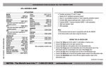
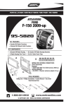
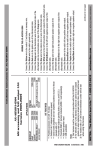
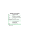
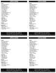
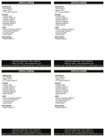
INSTAX-ADXSVI-CH3
INSTAX-ADXSVI-CH3
AX-ADXSVI-CH3
AX-ADXSVI-CH3
Dodge/RAM accessory and NAV output CAN harness 2013-up
• Provides accessory (12 volt 10 amp)
• Retains R.A.P. (retained accessory power)
• Used in non-amplified systems or when replacing amplified system
*Fiat 500L only: For use in both amplified and non-amplified systems
• Provides NAV outputs (parking brake, reverse, and V.S.S.)
• Prewired ASWC-1 harness included (ASWC-1 sold separately)
• Retains back-up camera (if through the OE radio)
• Retains the use of the 3.5mm AUX jack
• High level speaker input
• USB updatable
Note: This harness must be used in conjunction with the AX-ADXSVI
APPLICATIONS
DODGE
Dart (small screen option) 2013-up
Fiat
500L
2014-up
APPLICATIONS
RAM
1500, 2500, 3500
(small screen option) 2013-up
Chassis cab 3500, 4500, 5500 (small screen option)
2013-up
WIRING THE AX-ADXSVI-CH3
Connect the Yellow wire to the radio’s 12 volt battery or memory wire.
Connect the Black wire to the radio’s ground wire.
Connect the Red wire to the ignition wire of the aftermarket radio.
Connect the Orange wire to the illumination wire of the aftermarket radio. If the
aftermarket radio has no illumination wire, tape off the Orange wire.
• For the Fiat 500L only, connect the Blue/White wire to the amp turn on of the
aftermarket radio.
• Connect the White wire to the left front positive speaker output of the aftermarket radio.
• Connect the White/Black wire to the left front negative speaker output of the
aftermarket radio.
•
•
•
•
1-800-221-0932
REV. 12/19/13
DODGE
Dart (small screen option) 2013-up
Fiat
500L
2014-up
WIRING THE AX-ADXSVI-CH3
Connect the Yellow wire to the radio’s 12 volt battery or memory wire.
Connect the Black wire to the radio’s ground wire.
Connect the Red wire to the ignition wire of the aftermarket radio.
Connect the Orange wire to the illumination wire of the aftermarket radio. If the
aftermarket radio has no illumination wire, tape off the Orange wire.
• For the Fiat 500L only, connect the Blue/White wire to the amp turn on of the
aftermarket radio.
• Connect the White wire to the left front positive speaker output of the aftermarket radio.
• Connect the White/Black wire to the left front negative speaker output of the
aftermarket radio.
•
•
•
•
metraonline.com
© COPYRIGHT 2004-2013 METRA ELECTRONICS CORPORATION
RAM
1500, 2500, 3500
(small screen option) 2013-up
Chassis cab 3500, 4500, 5500 (small screen option)
2013-up
1-800-221-0932
REV. 12/19/13
metraonline.com
© COPYRIGHT 2004-2013 METRA ELECTRONICS CORPORATION
INSTAX-ADXSVI-CH3
INSTAX-ADXSVI-CH3
AX-ADXSVI-CH3
AX-ADXSVI-CH3
Dodge/RAM accessory and NAV output CAN harness 2013-up
• Provides accessory (12 volt 10 amp)
• Retains R.A.P. (retained accessory power)
• Used in non-amplified systems or when replacing amplified system
*Fiat 500L only: For use in both amplified and non-amplified systems
• Provides NAV outputs (parking brake, reverse, and V.S.S.)
• Prewired ASWC-1 harness included (ASWC-1 sold separately)
• Retains back-up camera (if through the OE radio)
• Retains the use of the 3.5mm AUX jack
• High level speaker input
• USB updatable
Note: This harness must be used in conjunction with the AX-ADXSVI
APPLICATIONS
DODGE
Dart (small screen option) 2013-up
Fiat
500L
2014-up
APPLICATIONS
RAM
1500, 2500, 3500
(small screen option) 2013-up
Chassis cab 3500, 4500, 5500 (small screen option)
2013-up
WIRING THE AX-ADXSVI-CH3
Connect the Yellow wire to the radio’s 12 volt battery or memory wire.
Connect the Black wire to the radio’s ground wire.
Connect the Red wire to the ignition wire of the aftermarket radio.
Connect the Orange wire to the illumination wire of the aftermarket radio. If the
aftermarket radio has no illumination wire, tape off the Orange wire.
• For the Fiat 500L only, connect the Blue/White wire to the amp turn on of the
aftermarket radio.
• Connect the White wire to the left front positive speaker output of the aftermarket radio.
• Connect the White/Black wire to the left front negative speaker output of the
aftermarket radio.
•
•
•
•
1-800-221-0932
REV. 12/19/13
metraonline.com
© COPYRIGHT 2004-2013 METRA ELECTRONICS CORPORATION
DODGE
Dart (small screen option) 2013-up
Fiat
500L
2014-up
RAM
1500, 2500, 3500
(small screen option) 2013-up
Chassis cab 3500, 4500, 5500 (small screen option)
2013-up
WIRING THE AX-ADXSVI-CH3
Connect the Yellow wire to the radio’s 12 volt battery or memory wire.
Connect the Black wire to the radio’s ground wire.
Connect the Red wire to the ignition wire of the aftermarket radio.
Connect the Orange wire to the illumination wire of the aftermarket radio. If the
aftermarket radio has no illumination wire, tape off the Orange wire.
• For the Fiat 500L only, connect the Blue/White wire to the amp turn on of the
aftermarket radio.
• Connect the White wire to the left front positive speaker output of the aftermarket radio.
• Connect the White/Black wire to the left front negative speaker output of the
aftermarket radio.
•
•
•
•
1-800-221-0932
REV. 12/19/13
metraonline.com
© COPYRIGHT 2004-2013 METRA ELECTRONICS CORPORATION
INSTAX-ADXSVI-CH3
INSTAX-ADXSVI-CH3
• Connect the Gray wire to the right front positive speaker output of the aftermarket radio.
• Connect the Gray/Black wire to the right front negative speaker output of the aftermarket radio.
• Connect the Green wire to the radio’s left rear positive speaker output.
• Connect the Green/Black wire to the radio’s left rear negative speaker output.
• Connect the Purple wire to the radio’s right rear positive speaker output.
• Connect the Purple/Black wire to the radio’s right rear negative speaker output.
The following wires are for the aftermarket radios that have navigation built in.
• Connect the Light Green wire to the parking brake wire of the aftermarket
navigation radio (if applicable).
• Connect the Blue/Pink wire to the VSS or speed sense wire of the aftermarket
navigation radio (if applicable).
• Connect the Green/Purple wire to the reverse wire of the aftermarket navigation
radio (if applicable).
• Cycle the key, by turning the ignition on for 30 seconds. Then off and on again to test the radio.
RCA Connections
• Connect the Yellow RCA to the "video in" of the aftermarket radio to retain the OE
back up camera (if equipped).
• Connect the White and Red RCA to the audio "AUX in" of the aftermarket radio to
retain the OE 3.5mm jack (if equipped).
AsWC-1 (if installing)
After the XSVI is initialized, plug in the ASWC-1 into the 12-pin harness of the AX-ADXSVI-CH3 and refer to the ASWC-1 instructions.
KNOWLEDGE IS POWER
Enhance your installation and fabrication skills by
enrolling in the most recognized and respected
mobile electronics school in our industry.
Log onto www.installerinstitute.com or call
800-354-6782 for more information and take steps
toward a better tomorrow.
Metra recommends MECP
certified technicians
1-800-221-0932
REV. 12/19/13
Caution: Metra recommends disconnecting the
negative battery terminal before beginning any
installation. All accessories, switches, and especially
air bag indicator lights must be plugged in before
reconnecting the battery or cycling the ignition.
Note: Refer to the instructions included with the
aftermarket radio.
metraonline.com
© COPYRIGHT 2004-2013 METRA ELECTRONICS CORPORATION
KNOWLEDGE IS POWER
Enhance your installation and fabrication skills by
enrolling in the most recognized and respected
mobile electronics school in our industry.
Log onto www.installerinstitute.com or call
800-354-6782 for more information and take steps
toward a better tomorrow.
Metra recommends MECP
certified technicians
1-800-221-0932
REV. 12/19/13
INSTAX-ADXSVI-CH3
Caution: Metra recommends disconnecting the
negative battery terminal before beginning any
installation. All accessories, switches, and especially
air bag indicator lights must be plugged in before
reconnecting the battery or cycling the ignition.
Note: Refer to the instructions included with the
aftermarket radio.
metraonline.com
© COPYRIGHT 2004-2013 METRA ELECTRONICS CORPORATION
INSTAX-ADXSVI-CH3
• Connect the Gray wire to the right front positive speaker output of the aftermarket radio.
• Connect the Gray/Black wire to the right front negative speaker output of the aftermarket radio.
• Connect the Green wire to the radio’s left rear positive speaker output.
• Connect the Green/Black wire to the radio’s left rear negative speaker output.
• Connect the Purple wire to the radio’s right rear positive speaker output.
• Connect the Purple/Black wire to the radio’s right rear negative speaker output.
The following wires are for the aftermarket radios that have navigation built in.
• Connect the Light Green wire to the parking brake wire of the aftermarket
navigation radio (if applicable).
• Connect the Blue/Pink wire to the VSS or speed sense wire of the aftermarket
navigation radio (if applicable).
• Connect the Green/Purple wire to the reverse wire of the aftermarket navigation
radio (if applicable).
• Cycle the key, by turning the ignition on for 30 seconds. Then off and on again to test the radio.
RCA Connections
• Connect the Yellow RCA to the "video in" of the aftermarket radio to retain the OE
back up camera (if equipped).
• Connect the White and Red RCA to the audio "AUX in" of the aftermarket radio to
retain the OE 3.5mm jack (if equipped).
AsWC-1 (if installing)
After the XSVI is initialized, plug in the ASWC-1 into the 12-pin harness of the AX-ADXSVI-CH3 and refer to the ASWC-1 instructions.
KNOWLEDGE IS POWER
Enhance your installation and fabrication skills by
enrolling in the most recognized and respected
mobile electronics school in our industry.
Log onto www.installerinstitute.com or call
800-354-6782 for more information and take steps
toward a better tomorrow.
Metra recommends MECP
certified technicians
1-800-221-0932
REV. 12/19/13
Caution: Metra recommends disconnecting the
negative battery terminal before beginning any
installation. All accessories, switches, and especially
air bag indicator lights must be plugged in before
reconnecting the battery or cycling the ignition.
Note: Refer to the instructions included with the
aftermarket radio.
metraonline.com
© COPYRIGHT 2004-2013 METRA ELECTRONICS CORPORATION