1
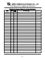
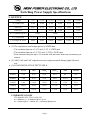
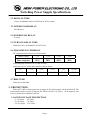
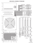
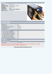
Part Name:
Model No: HPE-450-A12S
Document Version: A0
PRODUCT SPECIFICATION
Release Date: 2013/8/19
Approved by :
Checked by :
HIGH POWER ELECTRONIC CO., LTD
TEL: + 886-2-2659.2535
Fax : +886-2-2659.2265
Prepared by :
SIRFA International Co., Ltd.
TEL: +86-769-87720745
Fax :+86-769-87915210
Switching Power Supply Specifications
Subject:Change History of Specification
日期
版本
修訂
頁面
2013/8/19
A0
--
變 更 內 容
REF NO.
---
initial
Page 1
Switching Power Supply Specifications
Table of Contents
1 INPUT
1.1
1.2
1.3
1.4
1.5
1.6
1.7
1.8
VOLTAGE
FREQUENCY
CURRENT
INRUSH CURRENT
POWER EFFICIENCY
LEAKAGE CURRENT
POWER FACTOR
ErP REQUIREMENT
2 OUTPUT
2.1
2.2
2.3
2.4
2.5
2.6
2.7
REMOTE ON/OFF
HOLD-UP TIME
POWER GOOD DELAY
POWER FAIL DELAY
TURN-ON DELAY TIME
TRANSIENT OVERSHOOT
RISE TIME
3 PROTECTION
3.1
3.2
3.3
OVER VOLTAGE PROTECTION
SHORT PROTECTION
OVER POWER PROTECTION
4 ENVIRONMENT
4.1
4.2
4.3
4.4
4.5
4.6
OPERATING TEMP
STORAGE TEMP
OPERATING HUMIDITY
STORAGE HUMIDITY
OPERATING ALTITUDE
STORAGE ALTITUDE
5 HI-POT
5.1
PRIMARY TO SECONDARY
Page 2
Switching Power Supply Specifications
6 SAFETY AND EMC REQUIREMENTS
6.1
CONDUTED EMI
7 MTBF at 25℃ (demonstrated)
8 DIMENSIONS
Page 3
Switching Power Supply Specifications
1. INPUT:
1.1 VOLTAGE
MINIMUM
NOMINAL
MAXIMUM
UNITS
207
230
253
Vrms
1.2 FREQUENCY
47Hz ~ 63Hz
1.3 CURRENT
230Vac / 4.0A max.
1.4 INRUSH CURRENT
100A max. when AC input 230Vac and 25℃ cold start.
1.5 POWER EFFICIENCY
72% minimum under the load conditions defined in below table and 230Vac input.
Loading Table for Efficiency Measurements
450W(loading shown in Amps)
Loading
+12V1
+12V2
+5V
+3.3V
-12V
+5Vsb
Full
14.65
12.56
12.05
14.73
0.27
2.27
1.6 LEAKAGE CURRENT
3.5mA max.
1.7 POWER FACTOR
PF > 0.9 at 230Vac input
1.8 ErP REQUIREMENT
Meet ErP 2010 requirement
Page 4
Switching Power Supply Specifications
2. OUTPUT:
Voltage
+5V
+3.3V
+12V1
+12V2
-12V
+5Vsb
*(1) Max load
18.0A
22.0A
21.0A
18.0A
0.3A
2.5A
Min load
0.5A
0.3A
0.5A
0.5A
0.0A
0.0A
Peak load
--
--
24.0A
21.0A
--
3.0A
--
--
*(1) Combined power
120W
360W
*(3) Regulation
+5,-5%
+5,-5%
+5,-5%
+5,-5%
+10,-10%
+5,-5%
*(2) Ripple & Noise
50mV
50mV
120mV
120mV
120mV
50mV
* (1) The continuous total output power is 450W max.
‧The combined power of +5V and +3.3V is 120W max.
‧The combined power of +12V1 and +12V2 is 360W max.
‧Peak currents may last up to 12 seconds with not more than one occurrence per
minute.
* (2) Add 0.1uF and 10uF capacitors across output terminal during ripple & noise
test.
* (3) LOAD REGULATION TEST TABLE:
+3.3V
+5V
+12V1
+12V2
-12V
+5Vsb
LOAD1
0.3A
0.5A
0.5A
0.5A
0A
0A
LOAD2
7.0A
6.5A
7.0A
6.0A
0.15A
1.0A
LOAD3
9.0A
18.0A
15.0A
11.2A
0.3A
2.5A
LOAD4
22.0A
9.5A
15.0A
11.2A
0.3A
2.5A
LOAD5
7.0A
10.0A
17.0A
13.0A
0.3A
2.5A
2.1 REMOTE ON/OFF
TTL High/PS-OFF; TTL Low/PS-ON
VIL = 0.8Vmax, IIL = ‐1.6mAmax @Vin = 0.4V VIH = 2.0Vmin @ Iin = ‐200uA, VIH = 5.25Vmax @open ckt.
Page 5
Switching Power Supply Specifications
2.2 HOLD-UP TIME
13msec (minimum) at 80% of full load at 230Vac input.
2.3 POWER GOOD DELAY
100-500 msec.
2.4 POWER FAIL DELAY
>1 msec.
2.5 TURN-ON DELAY TIME
2000 msec max. At Nominal Line Full Load.
2.6 TRANSIENT OVERSHOOT
DC output transient step sizes as below table:
Output voltage
+5V
+3.3V
+12V1
+12V2
Max. step size
30%
30%
40%
40%
Load-changing repetition rate of 10m seconds.
Load slew rated 1.0A/uS and capacitive load as below :
+5V
+3.3V
+12V1
+12V2
-12V
+5Vsb
6000uF
6000uF
5000uF
3000uF
470uF
470uF
2.7 RISE TIME
20ms max at full load.
3. PROTECTION:
When OVP, OPP or short protection is triggered, the main outputs will be latched off. The
main outputs can be reset by cycling the DC remote on/off or AC power. +5Vsb output is auto
recovery when fault condition removed.
3.1 OVER VOLTAGE PROTECTION
+3.3V output
+5.0V output
+12.0V output
4.5 Vmax.
7.0 Vmax.
15.6 Vmax.
Page 6
Switching Power Supply Specifications
3.2 SHORT PROTECTION
All output to GND.
3.3 OVER POWER PROTECTION
Foldback at 110%~150% over peak load.
4. ENVIRONMENT:
4.1 OPERATING TEMP.
0℃ to +40℃
4.2 STORAGE TEMP.
-20℃ to +70℃
4.3 OPERATING HUMIDITY
20% to 90%, non-condensing
4.4 STORAGE HUMIDITY
5% to 95%, non-condensing
4.5 OPERATING ALTITUDE
0 to 10,000 feet
4.6 STORAGE ALTITUDE
0 to 50,000 feet
5. HI-POT:
5.1 PRIMARY TO SECONDRY
1800Vac for 1 minute
6. SAFETY AND EMC REQUIREMENTS
6.1 CONDUCTED EMI
CE
7. MTBF at 25℃(demonstrated)
80K hrs minimum
8. DIMENSIONS
WxLxH=150x140x86mm
Page 7