1
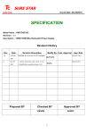
SURE STAR
Issued Date :Dec/06/2011
SURE STAR
SPECIFICATION
Model Name:
:R4B-600G1V2
Revision:
:1.1
Description:
:600W+600W Mini Redundant Power Supply.
Revision History
Rev.
1.0
Date
AUG.08
Revision Description
Modified the circuit for DC-DC backplane
2011
1.1
Dec.05
1. Add the “push button reset switch” on P.12.
2011
2. Modified the operation temp. to 50℃
Prepared BY
Modify By Cust. Approval
KEVIN
Jacky
Checked BY
KEVIN
App. Date
AUG.10, 2011
Dec.06, 2011
Approved BY
JACKY
①
SURE STAR
SURE STAR
Contents
1. General Description
2. Input Characteristics
2.1. AC Input voltage and frequency
2.2. Input current and inrush current
2.3. Power Factor
3. Power Efficiency
4. Output Characteristics
4.1. Output Voltage & Current Regulation
4.2. DC Output Ripple & Noise
4.3. Hold Up Time
4.4. Rise Time
4.5. Dynamic load response time
4.6. Remote on/off control
5. Power good signal
6. PROTECTION
6.1. Over voltage protection
6.2. Under-voltage protection
6.3. Over current Protection
6.4. Short circuit protection
6.5. Thermal Protection
7. Power System Signal status
7.1. Buzzer status
7.2. LED indicators
7.3. TTL signal
8. Load sharing
②
SURE STAR
SURE STAR
9. Isolation
9.1. Insulation Resistance
9.2. Dielectric Withstand Voltage
9.3. Leakage current
10. Safety Requirements
11. EMC
11.1. EMI
11.2. EMS
12. Environmental
12.1. Temperature
12.2. Humidity
12.3. Altitude
12.4. Vibration
12.5. Shock
12.6. Cooling Method
13. Reliability
13.1 MTBF Qualification
14. Mechanical 2D Drawing and Power Connector
14.1. Outside Dimension
14.2. DC Output cables
③
SURE STAR
SURE STAR
1.
General Description
This specification describes the performance characteristics of a 600 watts hot swappable, 1+1
power system with +3.3V,+5V,+12V, -12V main DC outputs, and 5V standby outputs. The
system is configured to hold two identical 600W power supply modules, SURE STAR Model
R4B-600G1V2.
2.
Input Characteristics
2.1. AC Input voltage and frequency
Minimum
Nominal
Maximum
Unit
90
100~240
264
VAC
47
50~60
63
Hz
2.2. Input current and inrush current
AC Input Voltage
Inrush Current
MAX. Input Current
per power supply module per power supply module
115Vac
10A
25A
230Vac
5A
50A
2.3. Power Factor
3.
90Vac
115Vac
230Vac
264Vac
>0.99
>0.98
>0.95
>0.92
Power Efficiency
The Minimum efficiency of the power supply is 80% at full load and 115Vac/60HZ input.
④
SURE STAR
SURE STAR
4.
Output Characteristics
4.1. Output Voltage & Current Regulation
Output Voltage
Min. Current
Rated current
REGULATION
+3.3V
1A
25A
±5%
+5V
1A
25A
±5%
+12V
1A
49A
±5%
-12V
0A
0.8A
±5%
0.5A
3.5A
±5%
+5VSB
Note: The combined total power from 5V & 3.3V shall not exceed 180W.
4.2. DC Output Ripple & Noise
Output Voltage Ripple & Noise (Max.)
+3.3V
60mVp-p
+5V
60mVp-p
+12V
120mVp-p
-12V
120mVp-p
+5VSB
50mVp-p
Note:
1. Ripple & Noise bandwidth is set to 20MHz.
2.Use a 0.1uF ceramic capacitor in parallel with a 10uF electrolytic capacitor at output
connector terminals for ripple & noise measurements.
4.3. Hold Up Time
Output Voltage
115VAC Input
230VAC Input
+3.3V
>16ms
>16ms
+5V
>16ms
>16ms
+12V
>16ms
>16ms
-12V
>16ms
>16ms
+5VSB
>16ms
>16ms
Note: All of dc output at full load.
⑤
SURE STAR
SURE STAR
4.4. Rise Time
Output Voltage
115/230Vac Input & Full Load
+3.3V
20ms (max.)
+5V
20ms (max.)
+12V
20ms (max.)
-12V
20ms (max.)
+5VSB
20ms (max.)
Note: The rise time measured is when the output voltages rise from10% to 90% of
specified output voltage Vout observed on the channel waveform.
4.5. Dynamic load response time
The following shall apply to the 3.3 V, 5 V, and 12 V outputs:
Output voltage for each output shall recover to within 5 % of its steady state level in less
than 1 ms under the following conditions:
AC Input Voltage: 90VAC ~ 264VAC
Repetition rate of 100Hz with 50 % duty cycle
Output
Step Load Size
Load Slew Rate
Capacitive Load
+3.3V
30% to 100% to 30% load
0.5 A/u sec
6000uF
+5V
30% to 100% to 30% load
0.5 A/u sec
6000uF
+12V
60% to 100% to 60% load
1 A/u sec
6000uf
+5SB
0% to 100% to 0% load
0.5 A/u sec
350uF
4.6. Remote on/off control
The main outputs of this power supply (3.3V,5V,12V,-12V) shall be energized when input
signal*PSON is active. *PSON is an active low TTL compatible signal referenced to the +5V
standby common. This input signal shall be an open collector signal capable of sinking a
minimum of 1.6mA. When *PSON becomes inactive, the main outputs shall be disabled.
PSON Signal
PSU on
PSU off
LOW (0.8V max)
HI (2V max)
⑥
SURE STAR
SURE STAR
5.
Power good signal
The system shall have an active high TTL compatible signal capable of sinking 1mA and
sourcing 100uA. The signal shall become active within 100 to 500 ms from the instant +5V output
reaches a steady state level within the specified regulation limits. It shall become inactive at least
1 ms before +5V drops to below the lower regulation limit.
6.
Power good @ 115/230VAC , Full Load
200ms ~ 500ms
Power Fail @ 115/230VAC , Full Load
1ms (Min.)
Protection
6.1. Over voltage protection
Output
Min
Max
Comments
+3.3V
3.75V
4.3V
PSU shutdown
+5V
5.7V
6.9V
PSU shutdown
+12V
13V
14.3V
PSU shutdown
Note:The power supply shall be test at max AC voltage (230Vac) and min load
or no load.
6.2. Under-voltage protection
Output
Min
Max
Comments
+3.3V
2.0V
2.4V PSU shutdown
+5V
3.3V
3.7V PSU shutdown
+12V
8.5V
9.5V PSU shutdown
Note:The power supply shall be test at max AC voltage (230Vac) and min load
or no load.
6.3. Over current protection
Output
+3.3V
Over Current(Type)
≧27.5A
Over Current(Max.)
Comments
37.5A
PSU shutdown
+5V
≧27.5A
37.5A
PSU shutdown
+12V
≧45.1A
61.5A
PSU shutdown
Note:The over current protection should be tested at other load rating.
⑦
SURE STAR
SURE STAR
6.4. Short circuit protection
Output
Comments
+3.3V
PSU shutdown
+5V
PSU shutdown
+12V
PSU shutdown
Note:The Short circuit protection should be tested at other load rating.
6.5. Thermal Protection
The power supply shall go into thermal protection as the case temperature exceeds 86℃ (±5℃)
limit. The output shall recover only when the temperature becomes normal and AC power is turned
on again.
7. Power System Signal status
7.1. Buzzer status
Power Supply Condition
Buzzer status
No AC power to all PSU
OFF
AC present/Only Standby Output On
OFF
Power supply DC outputs ON and OK
OFF
Power supply failure
Beeping
7.2. LED indicators
Power Supply Condition
Power system status
Per Power Module status
LED Color
RED
GREEN
ORANGE
No AC power to all PSU
OFF
OFF
OFF
AC present/Only Standby Output On
ON
OFF
OFF
Power supply DC outputs ON and OK
OFF
ON
ON
Power supply failure
OFF
Blinking
OFF
⑧
SURE STAR
SURE STAR
7.3. TTL signal
POWER SUPPLY CONDITION
OUTPUT CONDITION
Min.
Max.
NORMAL(POWER SUPPLY ON)
3V
5.25V
FAILURE(POWER SUPPLY OFF)
0V
1V
8. Load sharing
Output Voltage
Load Current
Load Share Voltage
+12V
1A
+0.48V ~ +0.52V
+5V
1A
+0.33V ~ +0.37V
+3.3V
1A
+0.33V ~ +0.37V
9. Isolation
9.1. Insulation Resistance
Input To Output 500Vdc , 50M ohms Min.( at room Temperature)
Input To FG
500Vdc , 50M ohms Min.( at room Temperature)
Output To FG
Non Insulation
9.2. Dielectric Withstand Voltage
Input To Output 1834Vac (30 mA) for 1 Minute.
Input To FG
1834Vac (30 mA) for 1 Minute.
Output To FG
Non Insulation
9.3. Leakage current
3.5mA max. at 120~264Vac/50~60HZ.
10. Safety Requirements
-IEC 60950-1
-TUV EN 60950-1
-UL or cUL
-BSMI
-CCC
⑨
SURE STAR
SURE STAR
11. EMC
The power supply shall comply with the following criterion:
11.1. EMI
1) Conduction Emission:
A.EN55022:2006/A1:2007 CLASS A; EN55024:1998/A1:2001/A2:20003.
B.CISPR PUB.22 and FCC PART 15 SUBPART B CLASS A.
2) Radiated Emission :
A.EN55022:2006/A1:2007 CLASS A; EN55024:1998/A1:2001/A2:20003.
B.CISPR PUB.22 and FCC PART 15 SUBPART B CLASS A.
12. Environmental
12.1. Temperature
Operating : 0℃to +50℃
Non Operating: -20℃to +70℃
12.2. Humidity
Operating : 5% to 95%, non-condensing
Non Operating: 20% to 90%,non-condensing
12.3. Altitude
Operating: sea level to 7,000 feet
Non-operating: sea level to 40,000 feet
12.4. Vibration
10-55Hz, 19.6m/s²(2G), 3minutes period, 60minutes each along X, Y and Z axis.
12.5. Shock
49m/s²(5G),11ms, once each X, Y and Z axis.
12.6. Cooling Method
BY BALL BEARING DC FAN.
13. Reliability
13.1 MTBF Qualification
Using MIL - HDBK -217F the calculated MTBF>100,000 hours at 25℃
⑩
14. Mechanical 2D Drawing and Power Connector
14.1. Outside Dimension:199(D)x150(W)x86(H)mm
修訂
REVISIONS
記述
DESCRIPION
簽名 SING 日期 DATE
修改兩側螺絲孔,調高VR孔1mm,地線柱位置
May,21,10
版次 REV
CR808-1
1.1
1.2
修改支架標示位置
Nov,07,11
CR808-1
CR807-1
#6-32(x8)
容許公差:
材料規格
單位
TOLEANCES:
.XXX= ± .025 MATERIAL
審核者
繪圖者
核准者
.XX= ± .1
± .2 APPROVE BY CHECK BY DRAW BY
.X=
圖號
投影法:
編號
UNITS
第三角法
⑪
SURE STAR
DRAW NO
SHEET
PROJECTION:
mm
日期
DATE
OF
品名
MODEL NO
料號
Nov,07,2011 PART NO
R4B
14.2. DC Output cables
1
2
3
4
5
PK
(1-3)
(4-6)
(7-9)
(10-12)
(13-15)
L=500mm±15mm
黑色編織網300mm
PIN24
24Pins(EPS12V)
Connector HOUSING: MOLEX 39-01-2240 or equivalent
TERMINAL: MOLEX 39-00-0039 or equivalent
PIN12
L=150mm+/-10mm
Housing
PL
1
2
3
4
5
(1-3)
(4-6)
(7-9)
(10-12)
(13-15)
PM
1
2
3
4
5
(1-3)
(4-6)
(7-9)
(10-12)
(13-15)
P24
PIN13
1
2
3
4
5
PN
PIN8
(1-3)
(4-6)
(7-9)
(10-12)
(13-15)
L=500mm±15mm
PIN5
PIN4
PIN3
P6
PIN1
PIN4
PW1 LED
PA
ORANGE
5 LED
PW2 LED
ORANGE
PB
External LED
RED / ORANGE
2 510
TTL Signal Cable
PC
H2510
PD
PIN1
PIN2
PIN3
PIN4
PIN1
PIN2
PIN3
PIN4
Connector HOUSING: MOLEX 39-01-0280 or equivalent
TERMINAL: MOLEX 39-00-0060 or equivalent
Housing
Pin WIRE
No. COLOR
P6
SIGNAL
YELLOW
YELLOW
YELLOW
BLACK
BLACK
BLACK
1
2
3
4
5
6
+12V
+12V
+12V
COM
COM
WIRE
TYPE
18AWG
18AWG
18AWG
18AWG
18AWG
18AWG
P4
PF
PIN1
PIN2
PIN3
PIN4
COM
Name
WIRE COLOR
WIRE
TYPE
LED COLOR
PW1LED BROWN
WHITE
ORANGE
22AWG
PW2LED RED
WHITE
ORANGE
22AWG
External LED
WHITE RED/ORANGE 22AWG
GREEN
LENGTH
1
2
BLACK
RED
SIGNAL
COM
+5V
1
2
GRAY
GRAY
PF
PI
WIRE
TYPE
LENGTH
22AWG
22AWG
900mm ±20mm
SIGNAL
WIRE
TYPE
LENGTH
COM
REST
22AWG
22AWG
900mm ±20mm
PG
PIN1
PIN2
PIN3
PIN4
PH
PIN1
PIN2
PIN3
PIN4
PJ
RED(+5V)
500mm/18AWG
BLACK(GND)
500mm/18AWG
GRAY(PG)
500mm/20AWG
PURPLE(+5VSB) 500mm/18AWG
YELLOW(+12V) 500mm/18AWG
YELLOW(+12V) 500mm/18AWG
ORANGE(+3.3V) 500mm/18AWG
500mm/18AWG
500mm/18AWG
500mm/18AWG
BLACK(GND)
BLACK(GND)
500mm/18AWG
500mm/18AWG
BLACK(GND)
NC
RED(+5V)
500mm/18AWG
RED(+5V)
500mm/18AWG
RED(+5V)
500mm/18AWG
BLACK(GND)
500mm/18AWG
BLACK
BLACK
BLACK
BLACK
YELLOW
YELLOW
YELLOW
YELLOW
WIRE
TYPE
SIGNAL
COM
COM
COM
COM
+12V
LENGTH
18AWG
18AWG
18AWG
18AWG
18AWG
18AWG
18AWG
+12V
+12V
+12V
500mm ±15mm
18AWG
1
2
3
4
BLACK
BLACK
YELLOW
YELLOW
WIRE
TYPE
SIGNAL
COM
COM
+12V
+12V
LENGTH
18AWG
18AWG
18AWG
500mm ±15mm
18AWG
1 YELLOW
2 BLACK
3 BLACK
4 RED
1 YELLOW
2 BLACK
3 BLACK
4 RED
1 YELLOW
2 BLACK
3 BLACK
4 RED
1 YELLOW
2 BLACK
3 BLACK
4 RED
WIRE
SIZE
SIGNAL
+12V
COM
COM
+5V
+12V
COM
COM
+5V
+12V
COM
COM
+5V
+12V
COM
COM
+5V
LENGTH
18AWG
18AWG
500mm ±15mm
18AWG
18AWG
18AWG
18AWG
150mm ±15mm
18AWG
18AWG
18AWG
18AWG
150mm ±15mm
18AWG
18AWG
22AWG
22AWG
150mm ±15mm
22AWG
22AWG
HOUSING: MOLEX 675820000 or equivalent
TERMINAL: MOLEX 675810000 or equivalent
Pin WIRE
Housing No.
COLOR
L=150mm+/-10mm
PI
PK
PIN1
PIN2
PIN3
PIN4
PM
PJ
1
2
3
4
5
ORANGE
BLACK
RED
BLACK
YELLOW
Pin WIRE
Housing No.
COLOR
L=150mm +/-10mm
22AWG 1007
PL
1
2
3
4
PN
容許公差:
TOLEANCES:
.XXX=
.XX=
.X=
1
2
3
4
5
ORANGE
BLACK
RED
BLACK
YELLOW
材料規格
+3V3
COM
+5V
COM
+12V
+3V3
COM
+5V
COM
+12V
繪圖者
第三角法
JACKY
500mm ±15mm
18AWG
18AWG
WIRE
TYPE
LENGTH
18AWG
18AWG
18AWG
150mm ±15mm
18AWG
18AWG
mm
SURE STAR
圖號
DRAW NO
編號
PROJECTION:
LENGTH
18AWG
18AWG
18AWG
SIGNAL
UNITS
審核者
WIRE
TYPE
SIGNAL
單位
MATERIAL
核准者
APPROVE BY. CHECK BY. DRAW BY.
投影法:
⑫
BLUE(-12V)
BLACK(GND)
GREEN(PS-ON) 500mm/20AWG
S.ATA HDD
L=150mm+/-10mm
ALARM Reset Switch Connector +Push Button Reset
Switch
Pin WIRE
No. COLOR
PE
PH
PC
900mm ±20mm
TTL Signal
Connector HOUSING: Molex 22-01-3027 or equivalent
Pin WIRE
No. COLOR
PD
PG
PB
L=500mm+/-15mm
POWER Module/System Status LED
500mm/18AWG
Pin WIRE
Housing No. COLOR
L=150mm+/-10mm
500mm ±15mm
500mm/18AWG
BLACK(GND)
4Pins(HD/CD-ROM/RW):P4H1~P4H4
Connector HOUSING: AMP 480424-0 or equivalent
TERMINAL:AMP 60619-4 or equivalent
4Pins(FLOPPY DISK):P4F
Connector HOUSING: AMP 171822-4 or equivalent
TERMINAL: AMP 170262-2 or equivalent
PIN1
PIN2
PIN3
PIN4
PE
500mm/18AWG
RED(+5V)
Pin WIRE
No. COLOR
PA
LENGTH
BLACK(GND)
4Pins(ATX12V,FOR P4)
Connector HOUSING: MOLEX 39-01-0280 or equivalent
TERMINAL: MOLEX 39-00-0060 or equivalent
PIN1
PIN2
PIN3
PIN4
PIN1
PIN2
PIN3
PIN4
14
15
16
17
18
19
20
21
22
23
24
1
2
3
4
5
6
7
8
P8
L=150mm+/-10mm
6Pins(PCI Express)
ORANGE(+3.3V) 500mm/18AWG
Pin WIRE
Housing No.
COLOR
L=500mm+/-15mm
Push Button
Reset Switch
Alarm Reset Switch Connector
2
3
4
5
6
7
8
9
10
LENGTH
ORANGE(+3.3V) 500mm/18AWG
ORANGE(+3.3Vs) 500mm/22AWG
PIN2
PIN1 P4
Housing
BLACK (COM)
RED (+5V)
13
PIN1
L=150mm+/-10mm
PIN1
PIN2
ORANGE(+3.3V) 500mm/18AWG
11
12
L=150mm+/-10mm
5 LED
Pin WIRE
LENGTH No.
COLOR
1
8Pins(EPS12V)
Connector HOUSING: MOLEX 39-01-0280 or equivalent
TERMINAL: MOLEX 39-00-0060 or equivalent
L=500mm+/-15mm
5 LED
Power Module/System Status LED
PIN4
P8
L=500mm±15mm
GREEN / WHITE
PIN1
L=500mm±15mm
L=150mm+/-10mm
RED / WHITE
Pin WIRE
No. COLOR
P24
L=500mm+/-15mm
BROWN / WHITE
Alarm Reset Switch Connector +Micro Switch
01
L=500mm+/-15mm
SHEET
日期
DATE
OF
品名
MODEL NO
料號
Dec.06.2011 PART NO
SS-R4B(9 )