1
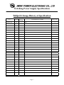
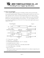
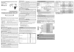
Part Name: 91.750BR.R1H01
Model No:
HPG-750BR-H14C (HP)
Document Version: A0
PRODUCT SPECIFICATION
Release Date: 2012/11/01
Approved by :
Checked by :
研發部
Prepared by :
2012.12.08
锺海明
HIGH POWER ELECTRONIC CO., LTD
TEL: + 886-2-2659.2535
Fax : +886-2-2659.2265
SIRFA International Co., Ltd.
TEL: +86-769-87720745
Fax :+86-769-87915210
Switching Power Supply Specifications
Subject:Change History of Specification
Date
Revision
Page of
Change
2012/11/01
A0
--
Description of Change
REF NO.
---
initial
Page 1
Switching Power Supply Specifications
Table of Contents
1 General
1.1
Scope
2 Input Characteristics
2.1
2.2
2.3
2.4
2.5
Input Voltage
Input Frequency
Max. Input AC Current
Inrush Current
Efficiency
3 Output characteristics
3.1
3.2
3.3
3.4
3.5
3.6
3.7
3.8
3.9
Nominal Operation Output
Remote On/Off controlled mode
Regulation
Rise Time
Hold-up Time
5 VSB
PG-OK
3.3V Sense
Capacitive Load
4 Protection
4.1
4.2
Input Protection
Output Protection
5 Start Stability
5.1
No Load Start
5.2 Cold Start
Page 2
Switching Power Supply Specifications
6 Environments
6.1
Temperature and Humidity
6.2
Altitude
6.3
Vibration and Shock
7 Conducted EMI
8 Product Safety
8.1
Safety Requirement
8.2
Leakage Current
8.3
Insulation Resistance
8.4
Dielectric Voltage Withstand
9 Power Good Signal
10 MTBF
11 Burn-In
11.1 Input Voltage t
11.2 Test Condition
12 Harmonics
13 Power Factor
14 Mechanical Specification
14.1 Outline Dimension
14.2 Weight
14.3 Pin Assignment
Page 3
Switching Power Supply Specifications
1. General
1.1 Scope
This specification defines the performance characteristics of a single phase 750 watts, 5
output power supply. This specification also defines worldwide safety and electromagnetic
compatibility requirements for the power supply which is intended for use in computer
products.
2. Input Characteristics
2.1 Input Voltage
Nominal Voltage
Voltage Variation Range
---------------------
----------------------------
230 Vrms
207 - 253 Vrms
2.2 Input Frequency
Nominal Frequency
Frequency Variation Range
------------------------
--------------------------------
50 Hz
47 Hz to 63 Hz
* The power supply must operate at above frequency with 207 - 253VACrms input voltage range.
2.3 Max. Input AC Current
Max. Input Current
Measuring Range
------------------------
-----------------------
6.3A
207 - 253 Vrms
2.4 Inrush Current
The power supply must meet inrush requirements for any rated AC voltage, during turn on
at any phase of AC voltage, during a single cycle AC dropout condition, during repetitive
ON/OFF cycling of AC, and over the specified temperature range. The peak inrush current
shall be less than the ratings of its critical components (including input fuse, bulk rectifiers,
and surge limiting device).
2.5 Efficiency
HPG-750BR-H14C provides an efficiency of 82% when measured at full load under
230V/50Hz condition.
Page 4
Switching Power Supply Specifications
3. Output characteristics
3.1 Normal Operation Output
Output
Load
Range
Ripple & Noise
Peak
Regulation
Voltage
MIN
MAX
1. +5V
0.2A
22.0A
±5%
50mV
2. +3.3V
0.1A
22.0A
±5%
50mV
3. +12V
0.6A
56.25A
±5%
120mV
4. -12V
0.0A
0.3A
±10%
120mV
5. +5Vs
0.0A
2.5A
±5%
50mV
3.5A
P-P Max.
z Maximum continuous total DC output power should not exceed 750W.
z Maximum continuous combined load on +3.3VDC and +5VDC outputs shall not exceed 130W.
z Maximum combined load on 12V outputs shall not exceed 675W.
NOTE:
Noise test should be measured with 20 MHz bandwidth frequency oscilloscope. The output terminal
shall add a tantalum capacitor of 10uF in parallel with a ceramic capacitor of 0.1uF.
3.2 Remote On/Off Controlled mode
The PSON# signal is required to remotely turn on/off the power supply, PSON# is an active
low signal that turns on the output power rails. When this is not pulled low by the system, or
left open, the outputs (except the +5VSB) turn off. This signal is pulled to a standby voltage
by a pull-up resistor internal to the power supply.
TTL level
"H" 2.0 V - 5.25 V
"L" 0.0 V – 1.0 V
3.3 Regulation
The cross regulation defined as follows, the output regulation should be within the specified
range.
Load
+5V
+3.3V
+12V
-12V
+5Vsb
Light Load.
2.86 A
2.86 A
10.28 A
0.05 A
0.46A
Typical Load
7.15 A
7.15 A
25.69A
0.14 A
1.14 A
Full Load
14.31 A
14.31 A
51.38A
0.27 A
2.28A
Page 5
Switching Power Supply Specifications
3.4 Rise Time
DC output rise time is less than 20 mS at nominal line and full load.
3.5 Hold-up Time
DC +5V output maintains at least 16mS , after power off , under 230V/50Hz 75%Load
condition.
3.6 5VSB
5VSB is requierd for the implementation of PS-ON described above. 5VSB is a standby
voltage that may be used to power circuits that require power input during the powereddown state of all power rails. The 5 VSB pin should deliver 5V ± 5% at a minimum of 2.5
A for PC board circuits to operate. Conversely, PC board should draw no more than 2.5A
maximum form this pin. This power may be used to operate circuits such as soft power
control.
3.7 PG-OK
PG-OK is a power good signal and should be asserted high by power supply to indicate
that the +5 VDC and +3.3 VDC outputs are above the under-voltage thresholds of the
power supply. When this signal is asserted high, there should be sufficient mains energy
stored by the converter to guarantee continuous power operation within specification.
Conversely, when either the +5VDC or the +3.3VDC output voltage falls below the under-voltage
threshold, or when mains power has been removed for a time sufficiently long so that power supply
operation is no longer guaranteed, PG-OK should be deasserted to a low state. See Figure 1 for a
representation of the timing characteristics of the PG-OK,PS-ON, and germane power rail
signals.
3.8 3.3V Sense
A default 3.3V sense line should be implemented pin 13 of the connector.
3.9 Capacitive Load
The power supply should be able to power up and operate normally with the following
capacitances simultaneously present on the DC outputs.
Output
Capacitive load (uF)
+5V
6000
+12V
8000
+3.3V
-12V
+5VS
6000
350
350
Page 6
Switching Power Supply Specifications
4. Protection
4.1 Input Protection
In primary circuit of the power supply , a protected fuse is inserted. Only internal fault of
the power supply will cause the fuse blown. Any overload or short circuit at DC output will
keep from fuse brown or fire hazard.
4.2 Output Protection
4.2.1 Under voltage protection
The +5V/+3.3V DC output are protected against the under voltage condition . range
value can't be exceed 3.3~3.7V at 5V terminal and 2.0~2.4V at 3.3V.
4.2.2 Over Voltage Protection
The +5V/+12V/+3.3V DC output are protected against the over voltage condition .
Maximum value can't be over 6.5V at 5V terminal and 15.5V at 12V, 4.3V at 3.3V.
4.2.3 Over Power Protection
The power supply can be used electronic circuit to limit the output current against
exceeding 50% of surge output power or protected against excessive power delivery
since short circuit of any output or over total power at high line.
4.2.4 Short Circuit Protection
Short circuit placed on +5V,+12V,+3.3V,-12V will latch off. +5VSB will autorecovery.
5. Start Stability
5.1 No Load Start
When power is applied to HPG-750BR-H14C with no load connected or under minimum
load connected, neither damage to power supply nor hazards to users will occur.
5.2 Cold Start
The power supply shall operate properly when first applied at normal input voltage and or
so maximum load after 4 hours storage in 0℃ environment.
Page 7
Switching Power Supply Specifications
6. Environments
6.1 Temperature and Humidity
6.1.1
Operating
Temperature
Relative Humidity
6.1.2 Storage
Temperature
Relative Humidity
0 to 35 oC
20 to 90 %
-40 to 70 oC
20 to 95 % noncondensing
6.2 Altitude
The power supply can operate normally at any altitude between 0 to 10000 feet.
6.3 Vibration and Shock
Sweep and resonance search for each of X,Y,Z, axis at the sweep.
RATE of 1/OCTAVE/Min.
Frequency
5-55-10 Hz
Duration
30 minutes
Amplitude
0.35 mm
7. Conducted EMI
8. Product Safety
8.1 Safety Requirement
TUV, CB,CCC
8.2 Leakage Current
The AC leakage current is less than 3.5mA when the power supply connect to
253Vac/50Hz .
8.3 Insulation Resistance
The insulation resistance should be not less than 30M ohm after applying of 500VDC for 1
minute.
8.4 Dielectric Voltage Withstand
The power supply shall withstand for 1 minute without breakdown the application of a
60Hz 1500V AC voltage applied between both input line and chassis (20mA DC cut-off
current). Main transformer shall similarly withstand 3000Vac applied between both
primary and secondary windings for a minimum of one minute.
Page 8
Switching Power Supply Specifications
9. Power Good Signal
A TTL compatible signal for the purpose of initiating an orderly start-up procedure under
normal input operating conditions. During power up, this signal is asserted ( low ) until +5V is
under regulation and AC reaches min. line specification range. After all voltage are going
appropriate level, the system may have a turn on delay of 100mS, but no greater than 500mS.
During power off the signal should go to low level before +5V is out of regulation. The low
level is 0 to 0.8V and high level is 4.75 to 5.25V. The " Power Good "signal can drive up to 6
standard TTL loads.
Time Diagram
Figure 1
* T1 : Turn on time ( 2 sec. Max.)
* T2 : Rise time ( ≦ 20mS Max.)
* T3 : Power good turn on delay time ( 100 < T3 < 500 mS )
* T4 : Switch on time (0.5 sec. Max.)
* T5 : Power good turn off delay time ( 1.0 mS Min.) PS-ON/OFF
* T6 : Power hold-up time ( 16 mS Min.)
* Power on-off cycle :
When the power supply is turned off for a minimum of 2.0 sec. and turn on again, the power
good signal will be asserted.
Page 9
Switching Power Supply Specifications
10. MTBF
The MTBF of the power should be 50,000 hours min.
11. Burn-In
11.1 Input Voltage
Applying 220Vac for230Vac model.
11.2 Test Condition
Applying 75% loads for the power supply in 40 (+/-5) oC chamber for 4 hours.
12. Harmonics
The product shall meet requirement for EN61000-3-2 & EN61000-3-3 :2003 standard of class
D, test at 230Vac 50Hz.
13. Power Factor
The power supply with active power factor correction, and meet the EN61000-3-2 standards,
The power factor is greater than 0.9 at 230V/50Hz, Max. load.
14. Mechanical Specification
14.1 Outline Dimension
Please refer the mechanical drawing of HPG-750BR-H14C.
14.2 Weight
Maximum weight is 1.75 Kgs.
14.3 Pin Designation
14.3.1 DC CONNECTOR REQUIREMENTS
List or recognized component appliance wiring material(AVLV2),CN,rated min
850C ,300VAC shall be used for all output wiring.
Page 10
Switching Power Supply Specifications
14.3.2 BASEBOARD CONNECTOR
PA Connector:MOLEX 39-01-2200 or Approved Equivalent
18 AWG Wire
Signal
Orange
+3.3 VDC
Brown
+3.3V (SENSE)
Blue
Pin
Pin Signal
18 AWG Wire
13
1
+3.3 VDC
Orange
-12 VDC
14
2
+3.3 VDC
Orange
Black
COM
15
3
COM
Black
Green
PS-ON
16
4
+5 VDC
Red
Black
COM
17
5
COM
Black
Black
COM
18
6
+5 VDC
Red
Black
COM
19
7
COM
Black
None
20
8
PWR_OK
Gray
Red
+5 VDC
21
9
+5 Vsb
Purple
Red
+5 VDC
22
10 +12 VDC
Yellow
Red
+5 VDC
23
11 +12 V DC
Yellow
Black
COM
24
12 +3.3 VDC
Orange
PA1
14.3.3 Peripheral Connectors
PG/PH/PI
PM
Connector : AMP 1-480424-0 or MOLEX
Connector : AMP 171822-4 or approved
8981-04P or approved equivalent
equivalent
Pin
Signal
18AWG Wire
Pin Signal
1
+12 V DC
Yellow
1
+5 VDC
Red
2
COM
Black
2
COM
Black
3
COM
Black
3
COM
Black
4
+5 VDC
Red
4
+12 V DC
Yellow
Page 11
22AWG Wire
Switching Power Supply Specifications
14.3.4 +12V Power Connector
PB Connector : Molex 39-01-2040 or equivalent
Pin Signal
18 AWG Wire
1 COM
Black
2 COM
Black
3 COM
Black
4 COM
Black
5 +12 V DC
Yellow
6 +12 V DC
Yellow
7 +12 V DC
Yellow
8 +12 V DC
Yellow
14.3.4 Serial ATA Power Connector
PE/PF Connector : MOLEX 88751 or equivalent
Pin Signal
18AWG Wire
1 +3.3V DC
Orange
2 COM
Black
3 +5 VDC
Red
4 COM
Black
5 +12V DC
Yellow
14.3.6 PCI Power Connector
PC/PC1/PD/PD1 Connector : MOLEX 88751 or equivalent
Pin Signal
18 AWG Wire
1 +12V DC
Yellow
2 +12V DC
Yellow
3 +12V DC
Yellow
4 COM
Black
5 COM
Black
6 COM
Black
Page 12