1
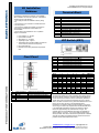
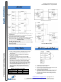
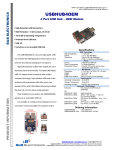
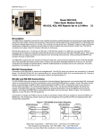
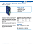
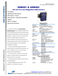
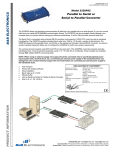
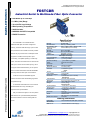
B&B ELECTRONICS pn 8684R0 FOSTCDR-0812ds page 1/5 ©2010 B&B Electronics. All rights reserved FOSTCDR Industrial Serial to Multimode Fiber Optic Converter Data Rates up to 115.2 kbps 2.5 Mile (4 km) Range 10 to 30 VDC Input Voltage Wide Operating Temperature 2000V Isolation MODBUS ASCII/RTU Compatible EMI/RFI Protection Specifications The FOSTCDR is our Industrial Serial to Multimode Fiber Optic Converter. Designed for industry, it extends serial data range up to 2.5 miles and provides the most versatile connection possible between any asynchronous full or half-duplex serial RS-232 RS-485 2-Wire RS-422/485 4-Wire Serial Connector Data Rate RS-232 RS-422/485 Isolation Industrial Bus equipment. In addition to direct point-to-point connectivity, it is capable operating in a multi-drop mode. This allows one serial device to communicate with up to 31 others around a fiber optic ring. Since it supports mixed serial standards, you can replace Type / Wavelength Output Power Receive Sensitivity Cable Connector Data Rate Maximum Distance Idle State other converters and isolators and add the EMI/RFI immunity inherent to fiber optic communications. PRODUCT INFORMATION In RS-232 mode, the FOSTCDR supports transmit and receive data. Handshaking signals are not passed through. Source Input Voltage Power Consumption Connector LED Indicators Dimensions Enclosure Weight An Automatic Send Data Control circuit controls Op Temperature Storage Temp Op Humidity the RS-422/485 driver chip, eliminating the requirement for special software. Approvals Easy to install and configure, it has an 8 position MTBF DIP Switch to set up the RS-422/485 parameters MTBF Calc. Method and terminal blocks to connect serial signals and power. Serial Technology TD, RD, GND Data A(-), Data B(+), GND TDA(-), TDB(+), RDA(-), RDB(+), GND Terminal Block (24 to14 AWG) Up to 115.2 Kbps Up to Up to 460.8 Kbps 2KV RMS, 1 minute MODBUS ASCII/RTU Fiber Optic Technology Multi-mode / 820 nm (-) 17 to (-) 10 dBm (-) 25.4 dBm to (-) 24 dBm 62.5/125 micro-meter ST 9.6 TO 115.2 kbps 2.5 miles (4 km) Transmitter Light ON Power External 10 to 30 VDC 4.2 Watts Terminal Block (24 to 14 AWG) Mechanical Serial TD, RD, and Power 4.3 x 2.3 x .95 in (11 x 9 x 2.5 cm) 35mm DIN Mount, Plastic 0.4 lbs (182 g) Environmental - 40 to 176°F (- 40 to 80°C) - 40 to 185°F (- 40 to 85°C) 0 to 95% Non-condensing Regulatory FCC, CE, cULus Recognized, File E222870 460854 hours MIL 217F Parts Count Reliability Prediction Ordering Information FOSTCDR Accessories MDR-40-12 Serial to Multimode Fiber Optic Converter Industrial Slim-line Power Supply www.bb-elec.com [email protected] [email protected] International Office: 707 Dayton Road PO Box 1040 Ottawa, IL 61350 USA 815-433-5100 Fax 433-5104 European Office: Westlink Commercial Park Oranmore Co. Galway Ireland +353 91 792444 Fax +353 91 792445 B&B ELECTRONICS UL Installation Guidance Underwriters Laboratories Conditions of Acceptability – When installed in the end-use equipment, consideration should be given to the following: 1. The wiring terminals are suitable for factory wiring only. 2. This device is to be mounted in a suitable enclosure in the end-product. 3. This device is suitable for operation at a maximum surrounding air temperature as described in the documentation. 4. These devices are intended for use in a pollution degree 2 environment. • • • • • Input Voltage: 10 – 30 VDC Input Power 4.2 Watts Wire Range: 12 – 24 AWG Tightening Torque: 4 kgf-cm Temperature rating of filed installed conductors is 105 C minimum, sized for 60 C ampacity. • Use copper wire only • Maximum surrounding ambient air temperature 80 C Front Panel PRODUCT INFORMATION pn 8684R0 FOSTCDR-0812ds page 2/5 ©2010 B&B Electronics. All rights reserved 1 2 3 4 5 6 Fiber Connectors PWR LED TD LED RD LED DIP Switch Terminal Blocks Terminal Block Terminal A B C D E F G H J K L DIP Switch (SW1) Pos 1 2 3 4 5 6 7 8 Multi-mode, ST Connectors ON When Power Applied On When Serial Data Transmitted On When Serial Data Received 8 Position Serial Data and Power Signal RS-232 RD (OUTPUT) GND GND RS-232 TD (INPUT) NOT CONNECTED +10 TO 30 VDC RS-422/485 TDA(-) / DATA A(-) RS-422/485 TDB(+) / DATA B (+) +10 TO 30 VDC RS-422/485 RDA(-) / DATA A (-) RS-422/485 RDB(+) / DATA B (+) ON OFF RS-422/485 Baud Rate Selection RS-422/485 Baud Rate Selection RS-422/485 Baud Rate Selection RS-422/485 Baud Rate Selection RS-422/485 Baud Rate Selection FO Multi-drop Ring FO Point-to-Point RS-422/485 Mode Selection RS-422/485 Mode Selection Baud 1 1200 2400 4800 9600 19.2K 38.4K 57.6K 76.8K 115.2 K 153.6K 230.4K 460.8K ON ON OFF OFF OFF OFF ON ON ON ON ON OFF 2 OFF OFF OFF OFF OFF ON OFF OFF ON OFF OFF OFF 3 4 OFF OFF OFF OFF ON OFF OFF ON ON OFF OFF OFF OFF OFF OFF ON OFF OFF OFF ON OFF OFF OFF OFF 5 OFF OFF ON OFF OFF OFF OFF OFF OFF OFF OFF OFF R9 820 kΩ 430 kΩ None None None None None None None 6.2 kΩ 4.3 kΩ 2.2 kΩ TIME OUT 8.20 ms 4.30 ms 2.20 ms 1.30 ms 0.56 ms 0.27 ms 0.22 ms 0.14 ms 0.10 ms 0.06 ms 0.04 ms 0.02 ms The Dip-Switch defines the mode of operation when being used for RS-422 or RS-485. Positions 1 through 5 determine the timeout of the RS-485 driver. Because the driver is controlled by hardware, a specific time must be set to tell the hardware how long to wait for data on the fiber side before turning off the RS-422/485 driver. If this time is set too short, the driver could be disabled before transmission is complete, resulting in data corruption. If the time is set too long, the device may respond before the RS-422/485 driver in the FOSTCDR is disabled, corrupting this response. Set the timeout for approximately one character time or longer. The character times for several different baud rates are selectable on switch positions 1 through 5. If you need a different timeout than what is provided, R10 can be removed and replaced with a different value R9. This table shows different timeout values for the switch positions as well as R9 replacement values. www.bb-elec.com [email protected] [email protected] International Office: 707 Dayton Road PO Box 1040 Ottawa, IL 61350 USA 815-433-5100 Fax 433-5104 European Office: Westlink Commercial Park Oranmore Co. Galway Ireland +353 91 792444 Fax +353 91 792445 B&B ELECTRONICS PRODUCT INFORMATION RS-422/RS-485 Mode Selection pn 8684R0 FOSTCDR-0812ds page 3/5 ©2010 B&B Electronics. All rights reserved RS-422 / RS-485 4-Wire 1. RS-422/485 mode is selected by positioning DIP Switch positions 7 and 8 as shown below. Mode RS-485 2-Wire RS-485 4-Wire RS-422 Position 7 ON ON OFF Position 8 ON OFF OFF RS-485 2-Wire 1. Loosen the screws to open the Serial TB Lead Clamps for the G, H, K, L, and M terminals. 2. Jumper terminal G to terminal K and connect to RS-485 Data A (-) lead. 3. Jumper terminal H to terminal L and connect to RS-485 Data B (+) lead. 4. Connect the signal ground lead to terminal M. 5. Tighten the screws to close the Serial TB Lead Clamps. Ensure the clamps hold the leads securely. However, do not over tighten. 6. Position DIP Switch positions 1 through 5 for t he desired baud rate. 7. Position DIP Switch positions 7 and 8 to ON for RS-485 2-Wire mode. Installation Notes: Not all RS-485 devices are marked correctly for Data (+) and (-), so if the slave devices don’t respond after going through the fiber converter, try swapping the wire pairs polarity to each converter. When there is no light received from the fiber in, the receive indicator will be On. You can interconnect or loop back the transmit fiber on one unit to the receive input on the same unit to verity the receive light goes out. If the transmit light is lighted all the time without data, the polarity of the RS-485 is reversed, or there is not enough bias, or termination loads on the RS-485 bus. Normal bias before termination is about 3.8 to 4.0 VDC, Data (+) to (-). See our RS-422/485 Application note for more information on biasing. 1. Loosen the screws to open the Serial TB Lead Clamps for the G, H, K, L, and M terminals. 2. Connect RS-422/485 signal leads as shown in the diagram. 3. Connect the signal ground lead to terminal M. 4. Tighten the screws to close the Serial TB Lead Clamps. Ensure the clamps hold the leads securely. However, do not over tighten. 5. Position DIP Switch positions 1 through 5 for t he desired baud rate. 6. Position DIP Switch positions 7 to ON and 4 to OFF for RS485 4-Wire mode. Set DIP Switch positions 7 and 8 to OFF for RS-422 mode. Installation Notes: Not all RS-485 devices are marked correctly for Data (+) and (-), so if the slave devices don’t respond after going through the fiber converter, try swapping the wire pairs polarity to each converter. When there is no light received from the fiber in, the receive indicator will be On. You can interconnect or loop back the transmit fiber on one unit to the receive input on the same unit to verity the receive light goes out. If the transmit light is lighted all the time without data, the polarity of the RS-485 is reversed, or there is not enough bias, or termination loads on the RS-485 bus. Normal bias before termination is about 3.8 to 4.0 VDC, Data (+) to (-). See our RS-422/485 Application note for more information on biasing. www.bb-elec.com [email protected] [email protected] International Office: 707 Dayton Road PO Box 1040 Ottawa, IL 61350 USA 815-433-5100 Fax 433-5104 European Office: Westlink Commercial Park Oranmore Co. Galway Ireland +353 91 792444 Fax +353 91 792445 B&B ELECTRONICS pn 8684R0 FOSTCDR-0812ds page 4/5 ©2010 B&B Electronics. All rights reserved RS-232 Fiber Optic Point-to-Point 1. Loosen the screws to open the Serial TB Lead Clamps for the D, A, and B terminals. 2. Insert the RS-232 Signal Leads into the TB. Refer to the diagram above for DTE and DCE wiring configurations. 3. Tighten the screws to close the Serial TB Lead Clamps. Ensure the clamps hold the leads securely. However, do not over tighten. Installation Notes: • DIP Switch Positions 1 through 5, 7 and 8 are not used in RS232 Mode. Set switch 6 to OFF. • The wiring example shows a DTE device on one end and a DCE device on the other. • Handshaking signals are not passed through. PRODUCT INFORMATION Fiber Optic Fiber Optic Multi-drop Ring RS-232 Loopback Test 1. Ensure your fiber optic cable is terminated with an ST type connector. 62.5/125 micro-meter multimode cable is recommended. 2. Connect the converter’s transmitter to the distant end receiver and vice-versa. 3. The fiber optic transmitter light is ON in the idle state. Therefore, the RX indicator will be lighted when data is not being transferred. 4. DIP Switch SW1-6 is used to select point-to-point or multidrop mode. For point-to-point, set the switch to OFF for both converters. For multi-drop, set the switch to ON for each converter in the ring. With SW1-6 in the ON position, receive data will be looped back to the fiber optic transmitter. Data will repeat around the ring until it finally reaches its source. When the data is received by the originator, timeout circuitry will prevent it from being retransmitted. Maximum Converters in a Fiber Ring Baud Rate RS-232 RS-422/485 19.2 kbps and lower 32 32 38.4 kbps 16 24 115.2 kbps 2 8 1. Configure the converter for RS-232. 2. Set DIP Switch SW1-6 to OFF. 3. Cross-connect the fiber optic transmitter to the fiber optic receiver using a multimode patch cord. 4. Connect a PC to the serial port. 5. Using Hyper Terminal or similar program, connect to the appropriate COM port. Set the baud rate to match the converter. Ensure Hyper Terminal local echo is OFF. 6. Transmit data. If the same character string is returned, the test is good. www.bb-elec.com [email protected] [email protected] International Office: 707 Dayton Road PO Box 1040 Ottawa, IL 61350 USA 815-433-5100 Fax 433-5104 European Office: Westlink Commercial Park Oranmore Co. Galway Ireland +353 91 792444 Fax +353 91 792445 B&B ELECTRONICS pn 8684R0 FOSTCDR-0812ds page 5/5 ©2010 B&B Electronics. All rights reserved Power An external 10 to 30 VDC power supply is required. Attach power leads as shown above. Power use is 4.2 Watts. PRODUCT INFORMATION Mechanical Diagram www.bb-elec.com [email protected] [email protected] International Office: 707 Dayton Road PO Box 1040 Ottawa, IL 61350 USA 815-433-5100 Fax 433-5104 European Office: Westlink Commercial Park Oranmore Co. Galway Ireland +353 91 792444 Fax +353 91 792445