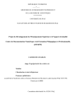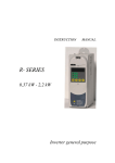
1
USER MANUAL IPC MINI REDUNDANT POWER SUPPLY Solutions: For IPC, Server, Storage, Workstation, Networking and Disk Array System. Model Name: R4B-500/600/700/800G1V2 (Rear) R4B-500/600/700/800GFV2 (Front) INDEX 1.1 INTRODUCTION 1.2 PACKING 1.3 SPECIFICATIONS 1.4 DRAWING 1.5 INSTALLATION & TESTING 1.6 HOT SWAP PROCEDURES 1.7 PIN-OUTS AND FUNCTION OF THE CONNECTORS 1.8 BUILT IN THERMAL CONTROL 1.9 TROUBLE SHOOTING 2 1.1 INTRODUCTION COMIX thank you for purchasing R4B series PS II size mini redundant power supply. The R4B series is a 1+1 hot-swappable / hot-pluggable redundant power supply. It consists of, A) Complete metal frame with compact size power modules. B) Backplane board. The R4B Series of hot swappable mini redundant power supply offer maximum 500/600/700/800 watts of o utput power. The series provide Active Power Factor Correction (PFC) at full range AC input that complies with E N 61000-3-2 for CE norms. The units are compact as PS II form factor and all the power modules are built interior 40X40X20 mm ball bearing fans for better ventilation. The units also provide a warning sub -system, including LED display, buzzer alarm, TTL signal etc.. When all the power modules are at normal condition, it balances the load share through its parallel design and results in the increa sing reliability of the power system. In order to use the power supply more effectively and safety, we suggest that you read through this manual carefully in advance of the installation and any operation. 1.2 PACKING R4B box package should consist of the follo wing: A) R4B Mini Redundant power suppl ies x 1 set B) Power cord (option) x 1 C) Accessories pack / Brackets (option) x 1 D) User manual (option) x 1 3 1.3 SPECIFICATIONS Model Name:R4B-500G1V2 / R4B-500GFV2 ( 500W + 500W ) Input Characteristics: 1. Voltage: 90 ~ 264V AC Full rang e 2. Frequency: 47 ~ 63Hz 3. Input Current: 10.0A for 115VAC, 5.0A for 230VAC. 4. Inrush Current: 25A for 115VAC, 50A for 230VAC per power supply module. Output Characteristics: Output Voltage Min. Current Max. Current Regulation Ripple & Noise ( Max.) +3.3V 1A 25A ± 5% 60mVp-p +5V 1A 25A ± 5% 60mVp-p +12V 1A 41A ± 5% 120mVp-p -12V 0A 0.8A ± 5% 120mVp-p +5VSB 0.5A 3.5A ± 5% 50mVp-p Note: The combined total power from 5V & 3.3V shall not exceed 1 70W. Features: AC Inlet in each module . Active Power Factor Correction (PFC). Hold up time > 16ms of DC output at full load. Compact size (PS II form factor). Balance load sharing design and power efficiency > 80%. Temperature range: Operation 0 ℃ ~ 50℃ , Storage -20℃ ~ 70℃ . Faulty alarm methods: LED, Buzzer, TTL Signal. Power protection: OPP, OVP, SCP, OCP, OTP . Over Power Protection: 130% ~ 160% Over Voltage Protection:+3.3V 3.75V~4.3V, +5V 5.7V~6.9V, +12V13V~14.3V. Over Current Protection:+3.3V 27.5A~37.5A, +5V27.5A~37.5A, +12V41.5A~61.5A. Meet EMI noise filter: FCC Class A , CISPR 22 Class A. Power good signal at 115/230VAC full load: 200ms to 500ms. Power fail: 1ms (Min.) Cooling: TW O 40mm DC Fans (module) . Dimensions: 150(W ) x 86(H) x 199(D) mm. 4 Model Name:R4B-600G1V2 / R4B-600GFV2 ( 600W + 600W ) Input Characteristics: 1. Voltage: 90 ~ 264V AC Full range 2. Frequency: 47 ~ 63Hz 3. Input Current: 10.0A for 115VAC, 5.0A for 230VAC. 4. Inrush Current: 25A for 115VAC, 50A for 230VAC per power supply module. Output Characteristics: Output Voltage Min. Current Max. Current Regulation Ripple & Noise ( Max.) +3.3V 1A 25A ± 5% 60mVp-p +5V 1A 25A ± 5% 60mVp-p +12V 1A 49A ± 5% 120mVp-p -12V 0A 0.8A ± 5% 120mVp-p +5VSB 0.5A 3.5A ± 5% 50mVp-p Note: The combined total power from 5V & 3.3V shall not exceed 1 80W. Features: AC Inlet in each module . Active Power Factor Correction (PFC). Hold up time > 16ms of DC output at full load. Compact size (PS II form factor). Balance load sharing design and power efficiency > 80%. Temperature range: Operation 0 ℃ ~ 50℃ , Storage -20℃ ~ 70℃ . Faulty alarm methods: LED, Buzzer, TTL Signal. Power protection: OPP, OVP, SCP, OCP, OTP. Over Power Protection: 130% ~ 160% Over Voltage Protection:+3 .3V3.75V~4.3V,+5V5.7V~6.9V,+12V13V~14.3V. Over Current Protection:+3.3V 27.5A~37.5A, +5V27.5A~37.5A, +12V53.9A~73.5A. Meet EMI noise filter: FCC Class A, CISPR 22 Class A. Power good signal at 115/230VAC full load: 200ms to 500ms. Power fail: 1ms (Min.) Cooling: TW O 40mm DC Fans (module) . Dimensions: 150(W ) x 86(H) x 199(D) mm. 5 Model Name:R4B-700G1V2 / R4B-700GFV2 ( 700W + 700W ) Input Characteristics: 1. Voltage: 90 ~ 264V AC Full range 2. Frequency: 47 ~ 63Hz 3. Input Current: 1 2.0A for 115VAC, 6.0A for 230VAC. 4. Inrush Current: 30A for 115VAC, 60A for 230VAC per power supply module. Output Characteristics: Output Voltage Min. Current Max. Current Regulation Ripple & Noise ( Max.) +3.3V 1A 32A ± 5% 60mVp-p +5V 1A 25A ± 5% 60mVp-p +12V 1A 57A ± 5% 120mVp-p -12V 0A 0.8A ± 5% 120mVp-p +5VSB 0.5A 3.5A ± 5% 50mVp-p Note: The combined total power from 5V & 3.3V shall not exceed 1 90W. Features: AC Inlet in each module . Active Power Factor Correction (PFC). Hold up time > 16ms of DC output at full load. Compact size (PS II form factor). Balance load sharing design and power efficiency > 80%. Temperature range: Operation 0 ℃ ~ 50℃ , Storage -20℃ ~ 70℃ . Faulty alarm methods: LED, Buzzer, TTL Signal. Power protection: OPP, OVP, SCP, OCP, OTP. Over Power Protection: 130% ~ 160% Over Voltage Protection:+3.3V 3.75V~4.3V,+5V5.7V~6.9V,+12V13V~14.3V. Over Current Protection:+3.3V 35.2A~48A, +5V27.5A~37.5A, +12V62.7A~85.5A. Meet EMI noise filter: FCC Class A, CI SPR 22 Class A. Power good signal at 115/230VAC full load: 200ms to 500ms. Power fail: 1ms (Min.) Cooling: TW O 40mm DC Fans (module) . Dimensions: 150(W ) x 86(H) x 199(D) mm. 6 Model Name:R4B-800G1V2 / R4B-800GFV2 ( 800W + 800W ) Input Characteristics: 1. Voltage: 90 ~ 264V AC Full range 2. Frequency: 47 ~ 63Hz 3. Input Current: 1 2.0A for 115VAC, 6.0A for 230VAC. 4. Inrush Current: 30A for 115VAC, 60A for 230VAC per power supply module. Output Characteristics: Output Voltage Min. Current Max. Current Regulation Ripple & Noise ( Max.) +3.3V 1A 32A ± 5% 60mVp-p +5V 1A 25A ± 5% 60mVp-p +12V 1A 65A ± 5% 120mVp-p -12V 0A 0.8A ± 5% 120mVp-p +5VSB 0.5A 3.5A ± 5% 50mVp-p Note: The combined total power from 5V & 3.3V shall not exceed 1 90W. Features: AC Inlet in each module . Active Power Factor Correction (PFC). Hold up time > 16ms of DC output at full load. Compact size (PS II form factor). Balance load sharing design and power efficiency > 80%. Temperature range: Operation 0 ℃ ~ 50℃ , Storage -20℃ ~ 70℃ . Faulty alarm methods: LED, Buzzer, TTL Signal. Power protection: OPP, OVP, SCP, OCP, OTP. Over Power Protection: 130% ~ 160% Over Voltage Protection: +3.3V3.75V~4.3V, +5V 5.7V~6.9V, +12V13V~14.3V. Over Current Protection: +3.3V35.2A~48A, +5V27.5A~37.5A, +12V71.5A~97.5A Meet EMI noise filter: FCC Class A, C ISPR 22 Class A. Power good signal at 115/230VAC full load: 200ms to 500ms. Power fail: 1ms (Min.) Cooling: TW O 40mm DC Fans (module) . Dimensions: 150(W ) x 86(H) x 199(D) mm. 7 1.5 INSTALLATION & TESTING Mount the power supply into the system chassis by using proper mounting tool. Attach the connectors to the motherboard by following it’s instructions, there are various connectors / pin-outs of both power supply and motherboard. Please ensure to connect the matched one; otherwise, the connection will cause unexpected harms. Connect the remaining power connectors to the various peripherals as needed. These connectors are “keyed”, so there will be only one possible way to connect them. Before applying power source to the system, make sure these is no loosed or incorrect connectors. Double check if all connection to the motherboard is matched properly. Maybe you would like to test the redundancy function before you out back the cover of your system chassis, then, please power it on. If the power system operates normally, the individual LEDs on power module and the external warning LED should be lighted. Now, remove one power module from the power system, the warning buzzer in the power system will sound, the external warning LED, which displays the status of the total power system, will change to be RED, the individual LED indicating the power module ’s status will distinguish. Meanwhile, the power system will continue to backup the power output without affecting the operation of your computing system. The warning buzzer will sound continuously. You can reset warning buzzer by pressing the buzzer reset switch. Insert the power module which is removed for test earlier. The sound of the warning buzzer will stop; the 10 external warning LED will turn to be GREEN again; the LED indicating the status of power module will light in GREEN. Test another power supply by performing the same procedure. If everything works out fine, then turn off the power system. Now put back the cover of the chassis and tighten with the screws which you have retained earlier. Now you have completed the testing and installation of R4B redundant power supply system. 1.6 HOT SWAP PROCEDURES Please refer to the following when either power module or the fan found defective. A) Locate the defective power module by examining the individual LED (if LED without light, it indicates the power module is defective). W ARNING: Please perform the above step carefully otherwise it may cause shut down the whole system. B) Turn off the individual on / off switch of the defective power module. W ARNING: Please do not remove the defective power module until you have worn gloves to keep from be burned. This is due to the cover of the power module is used as heat sink for cooling, usually the temperature is around 60 ~ 70 degree Celsius under full load condition. C) Remove the defective power module by pulling out method . W ARNING: Please put aside the power module await for cooling down. Keep from other people tough it until it is cool. 11 D) Replace a new good power module, insert the power module into the power system to the end. E) Turn on the power module. F) Check the LED of the power module, which should be in Green. G) Check the LED indicating the total power system status. It should be from twinkle to Green. Remarks: If the DC fan of the power module fails, you have to replace the power module. Please follow the same proce dures. 1.7 PIN-OUTS AND FUNCTION OF THE CONNECTORS ~ Please be aware of the polarity ~ 5LED BROWN / WHITE Power Module/System Status LED Name WIRE COLOR LED COLOR PW1LED BROWN WHITE PW2LED RED WHITE ORANGE WHITE GREEN/ORANGE External LED GREEN 5LED RED / WHITE ORANGE 5LED GREEN / WHITE TTL Signal Connector SIGNAL Pin No. WIRE COLOR 1 BLACK COM 2 RED +5V PIN1 PIN2 2510 BLACK (COM) RED (+5V) H2510 Alarm Reset Switch Connector Pin No. WIRE COLOR SIGNAL 1 GRAY COM 2 GRAY RESET PIN1 GRAY (COM) PIN2 GRAY (RESET) 187P 12 1.8 BUILT IN THERMAL CONTROL = LOW NOISE This small card can auto distinguished the power heats and fan speed. If power supply temp. get heating the speed should be go faster ; contrariwise. 1.9 TROUBLE SHOOTING If you have followed these directions correctly, there should be no problem occurred. Same common symptoms are: the system doesn’t work, buzzer sound, work for a very s hort period, etc., please try the following steps to verify and correct it: 1. Check all the connections (correct pin -outs, loose connectors, wrong direction, etc.). 2. Check for short-circuits or defective peripherals by unhooking each peripheral once at a time. When the system functions again, you have solved the problem. 3. Once you hear the buzzer sound or see the LED with RED light, please be aware of: a) If AC input voltage been set correct? b) If each power cord been well plugged into the AC in let? c) If the load is “under the minimum” or “over the maximum” load of each channel (please refer the Sec. 1. 3 specifications). Suppose the above condition been happened, please unplug the power cords, wait for 2 ~ 3 minutes for releasing the prot ection state, then test it again. 13 d) If buzzer still sound or the LED shows power module is defective, please locate which power module is defective, perform hot -swap procedure (please refer the Sec.1.7 Hot -swap procedures), sent the defective power module to your vendor for RMA operation. e) If you can not fix the problem, please contact with your vendor for supporting. Remarks: 1. Unambiguous reference to service document for instructions for replacement of fuses replaceable only by service perso nnel. 2. Caution: for continued protection against risk of fire, replace only with same type and rating of fuse. 3. Disconnect power supply cords before servicing. www.comix.com.tw 14