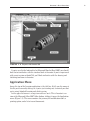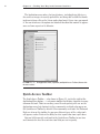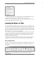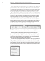
1
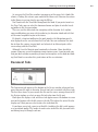
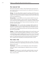
GH
TE
D
MA
TE
RI
AL
CHAPTER 1
CO
PY
RI
Finding Your Way
in the Inventor
Interface
Understanding Inventor’s interface behavior
Opening existing files
Creating new files
Modifying the look and feel of Inventor
Managing file locations
Accessing the Help system
2
C h a p t e r 1 • F i n d i n g Yo u r Wa y i n t h e I n v e n t o r I n t e r f a c e
Inventor’s User Interface
When you’re learning a new software application, it can sometimes seem as
though finding a tool is more difficult than learning to use it.
When Inventor first launches, you’re greeted with an opportunity to participate in the Customer Involvement Program (Figure 1.1). This program will
help Autodesk improve the product in the future. I highly recommend lending
a hand — your input may influence the future of the software you’re learning
today.
F I G U R E 1 . 1 Autodesk Customer Involvement Program sign-up dialog
After you’ve signed up for the Customer Involvement Program, you’ll be able
to view the Inventor interface. With no file loaded, you can immediately see its
simplicity. Let’s start by becoming familiar with the component of Inventor that
you’ll use every time you start the program: the graphical user interface (GUI).
Figure 1.2 shows the main components that we’ll review and expand on in this
chapter.
I n v e n t o r ’s U s e r I n t e r f a c e
F I G U R E 1 . 2 The parts of the Inventor GUI
If you’re used to the look and feel of Microsoft Word or Excel 2007, you should
find a lot of similarities with the standard tools in Inventor. If you’re experienced
with recent versions of AutoCAD, you’ll find similarities with the drawing and
sketching tool icons in Inventor.
Application Menu
Across the top of the Inventor application is the title bar. It tells you the name of
the file you’re currently editing; or, if you’re just starting out, it reminds you that
you’re using Autodesk Inventor and which version.
In the upper-left corner is a large icon with an I on it. This is Inventor’s version of the Microsoft Office 2007 Office button; clicking it opens the Application
menu (Figure 1.3). The menu contains the primary file-modification tools, a
printing option, and a list of recent documents.
3
4
C h a p t e r 1 • F i n d i n g Yo u r Wa y i n t h e I n v e n t o r I n t e r f a c e
The Application menu offers a lot great features, including being able to see
the names or images of recently opened files and being able to click the thumbtack icon to keep a file on the list no matter how long it’s been since you opened
it. You can also access the options for Autodesk Inventor that control its appearance and some aspects of its behavior.
F I G U R E 1 . 3 The Application menu (expanded) and Quick Access Toolbar (discussed in
the next section)
Quick Access Toolbar
The Quick Access Toolbar — also shown in Figure 1.3, just to the right of the
Application Menu button — is a dynamic toolbar that displays shortcuts to many
common file tools. Tools for creating a new file and opening a file are on the
Application menu, but shortcuts to these commonly used tools also appear on
the Quick Access Toolbar by default. Other commonly used tools, like Undo and
Redo, are also on this toolbar. As you open different types of files, other tools
will appear, such as Print or the ability to select a part color from a pull-down.
You can Add frequently used tools to the Quick Access Toolbar to save time
and eliminate the need to search for a tool that you use frequently.
L e a r n i n g t h e B a s i c s o f Ta b s
To add a tool, right-click the desired tool shown in the Ribbon below the title
bar, and select Add to Quick Access Toolbar from the context menu.
While we’re discussing fundamentals, let’s take a little time to review some of
the basic functions of the interface in general.
Learning the Basics of Tabs
The Autodesk Inventor 2010 interface is frequently referred to as a Ribbon interface because of the large ribbon of tools that is displayed horizontally across the
top of the screen. Depending on the type of file you’re editing, multiple tabs may
appear on the Ribbon. In each tab there are additional groupings of tools called
panels that offer even more precise organization.
In this book’s exercises, I’ll refer to the location of a tool by the tab and panel
on which it’s located. This should make it easier to locate new tools as they’re
introduced. When tools are reused, the specific location may not be given to
encourage learning their location.
Depending on your screen resolution, some panels will switch to a narrower,
expandable version to allow the primary tool to be displayed on the Ribbon.
Get Started Tab
Inventor is set up to open by default with no file or dialog boxes open. The interface displays only the Get Started tab (Figure 1.4) and behind it another tab
called Tools.
F I G U R E 1 . 4 The Get Started tab gives you access to the basic tools as well as
learning materials.
5
6
C h a p t e r 1 • F i n d i n g Yo u r Wa y i n t h e I n v e n t o r I n t e r f a c e
On the Get Started tab are the basic New, Open, and Projects tools. (We’ll talk
more about Projects later in this chapter.) These tools are in the Launch panel.
The Learn about Inventor panel and User Interface Overview panel contain tutorials that go into some of the concepts of the interface and provide easy access
to information about this version of Inventor and Inventor’s tools in general.
For an added touch, the Involvement panel offers quick access to the Autodesk
Education Community where students and teachers can access free software and
curricula. This panel also provides an important link to the Autodesk Customer
Involvement program, where you can participate in programs and tell Autodesk
what you like about Inventor or where you would like improvements made.
Inventor has a tradition of a dynamic interface. Inventor automatically offers
different tools based on the type of file you’re in or what you’re doing in that file.
For example, when you create a new Part file, Inventor begins the new file in a
sketch by default; therefore, the Sketch tab is active (Figure 1.5).
F I G U R E 1 . 5 Tabs that are automatically selected by Inventor are also highlighted.
Because Inventor is now primarily focused on these sketching tools, the
dynamically selected tab is highlighted in color; the bottoms of the tab’s panels
also appear in color. If you need to use a tool on another tab, the dynamically
selected tab’s highlight makes it easier to return to. To use a tab that Inventor
didn’t select, you only have to click the name of the tab.
Over the course of the following chapters and exercises, you’ll see that frequently,
Inventor presents the tab that you need most when you need it. You’ll also notice
in Figure 1.5 that not all tools are the same size, which makes it easier to find the
most commonly used tools. Some panels have a downward-pointing arrow next to
the panel name to show that you can access additional tools by clicking the arrow
and expanding the panel.
L e a r n i n g t h e B a s i c s o f Ta b s
If you find that you rarely use one of the tools, you can move it to the hidden portion of the panel by right-clicking the tool and selecting Move to
Expanded Panel.
You can also rearrange panels by clicking an individual panel’s title bar and
dragging it to a new location in the tab.
Some individual tools have options. For example, there is more than one type
of circle; so, next to the default circle you see a downward-pointing arrow.
Clicking this arrow expands the available options.
All of these tools have tooltips as well. Some of these are referred to as progressive tooltips; they give you basic information if you pause over the tool and then
provide illustrations or more in-depth information if you pause a little longer.
Ribbon Appearance
The Ribbon can also appear in different ways. The default appearance is referred
to as Normal (shown earlier, in Figure 1.5). To modify the overall appearance of
the Ribbon, right-click any part of the Ribbon and hover over the words Ribbon
Appearance until the list of options is displayed. You can also click the words
7
8
C h a p t e r 1 • F i n d i n g Yo u r Wa y i n t h e I n v e n t o r I n t e r f a c e
Ribbon Appearance if you’re in a hurry. Figures 1.6–1.8 show the Sketch tab in
different modes.
F I G U R E 1 . 6 The Sketch tab in Text Off mode
F I G U R E 1 . 7 The Sketch tab in Small mode
F I G U R E 1 . 8 The Sketch tab in Compact mode
The Ribbon itself can also be reduced in size to maximize screen space.
A small icon appears next to the tab names. Click it once, and the Ribbon is
reduced to showing only the panel names of the selected tab; a second click
removes the panels, leaving only the list of tabs. A third click of the button
restores the Ribbon to its full display in whatever mode you had selected.
Hovering over or clicking the collapsed panel name causes the panel to
expand, revealing the tools. If the panel name is concealed, click the tab name;
the Ribbon appears for a short time or until you select a tool or click another
part of the screen.
Selecting a tool on the Ribbon often causes a dialog box to appear on the
screen. Let’s review some of the things you need to know about dialog boxes.
Learning to Use the Dialog Boxes
Learning to Use the Dialog Boxes
One thing that makes Inventor easy to use is a kind of “graphical language” common to all the dialog boxes. These are items that behave consistently wherever
they appear. As you use Inventor, working with these items will become second
nature. As you’re getting started, knowing what to look for will make it easy to
understand what Inventor needs from you in order to accomplish your task.
Buttons
The following buttons and button states have the same effect no matter where
you encounter them in Inventor’s interface:
A button with a red arrow indicates that Inventor needs you to select something. Text may appear next to the arrow, identifying the type of input that
Inventor is looking for.
A button with a white arrow means that Inventor has been given the information it needs.
The OK button is grayed out until Inventor has the necessary user input to
execute an operation. Clicking OK initiates the command or function and closes
the dialog box.
The Apply button is also grayed out until Inventor has the necessary user
input to execute an operation. Clicking Apply initiates the command or function
but doesn’t close the dialog box. This allows you to execute the function and
start using it again immediately.
The Cancel button closes the dialog box without executing any operation.
The More button exposes additional options for a dialog box. After those options
become visible, the arrows then point to the left so you can hide the options again.
Any button with an ellipsis after the name launches another dialog box or
selection window when clicked.
Dialog Box Tabs
9
10
C h a p t e r 1 • F i n d i n g Yo u r Wa y i n t h e I n v e n t o r I n t e r f a c e
Another element of the common graphical language is the way dialog boxes are
organized. Many dialog boxes have tabs across the top, with each tab offering
additional options. Although most common functions are contained on the first
tab, when you begin working with a new dialog box, it’s worth taking a few
moments to explore the options on the other tabs. For example, in the Extrude
dialog box illustrated here, the Shape tab offers the basic options to select the
shape and define the distance it will be extruded, whereas the More tab offers
options to apply taper or draft to the shape.
Context Menus
You can access a large number of Inventor’s tools by clicking your secondary
mouse button — typically the right button — at different places on your screen.
As in other Windows software, right-clicking displays a context menu of options
that are relevant to what you’re doing at the time. In the exercises and examples
in this book, I’ll often instruct you to right-click and select the next operation
from a context menu.
To make it easier to get a feel for Inventor’s interface, let’s open a file to see the
changes that occur to the interface and get your first glimpse at its dynamic nature.
The Open Dialog Box
The tool to launch the Open dialog is available in several locations, as you probably noticed in the earlier parts of the chapter.
As in any contemporary software, this dialog box allows you to select a file or
files to open in Inventor, as shown in Figure 1.9. If you’re accustomed to
Microsoft Windows Explorer and some of its viewing options, this dialog box will
seem familiar. Using it should be comfortable for you right away. The dialog box
includes several components, and it’s important to understand what these parts
are and what they will do for you.
Inventor LT users see a slightly different Open dialog box. Inventor LT doesn’t
have assembly capabilities, so it doesn’t need some elements. It will still be beneficial for LT users to understand the capabilities of Inventor Suite or
Professional 2010 in case you use it in the future.
It’s possible to resize many dialog boxes by clicking and
dragging the corners, in order to allow easy viewing of the information
displayed.
N O T E
The Open Dialog Box
F I G U R E 1 . 9 File list displaying large icons
Shortcuts and the File List
At upper left in the Open dialog box is an area with a list of shortcuts to Frequently
Used Subfolders (Figure 1.10). You can customize this pane to create shortcuts to
folders that you’d like to access quickly. You can even set up subreferences and have
a structure that replicates the folder structure on your hard drive.
F I G U R E 1 . 1 0 Frequently Used Subfolders list
11
12
C h a p t e r 1 • F i n d i n g Yo u r Wa y i n t h e I n v e n t o r I n t e r f a c e
Centered in the dialog box and making up the bulk of it is the file list, where
the files are displayed. The File of Type option, described shortly, controls what
files are listed. You can open a file (or files) from here by selecting the
filename(s) and clicking OK or by double-clicking the filename.
At the top of the dialog box is the Look In field. This displays the name of
the folder whose files are currently displayed below it in the file list. The arrow
to the right allows you cascade the folder structure or to begin browsing for
other folders.
Navigation Controls
To the right of the Look In field are four icons that allow you to navigate easily
and to control how you view the files you’re looking for.
These tools share icons and functions with many standard Windows icons
and tools:
Go To Last Folder Visited The first button has an arrow pointing left. This button allows you to navigate back to the previous folder(s) you were browsing in. It
works on the same principle as the Back button in a web browser. When you’ve
just begun a session, the arrow is grayed out, because you don’t have any browsing history to recall.
Up One Level The next icon looks like a folder with a green arrow pointing up.
This takes you up a level in your folder structure from wherever you’re currently
browsing.
Create New Folder The third icon allows you to create a new folder in the
folder that you’re currently browsing in.
The View Menu The icon on the right is a fly-out tool that lets you change the
way the files you’re browsing are displayed. Depending on the operating system
you’re using, you see different options ranging from a detailed listing of dates
and file size to thumbnail previews of the files in the display area. In Figure 1.11,
you can see the same folder as in Figure 1.9 being browsed with the Thumbnail
display option.
You’ll find commonality in the controls between Inventor and many Microsoft
applications. This is done so that you don’t have to learn every aspect of the user
interface from scratch.
The Open Dialog Box
F I G U R E 1 . 1 1 File list showing Thumbnail view
File Display Options
Immediately below the file list are three selection pull-down lists that control
the file display options:
File Name This pull-down displays the full name of the selected file(s). If you
click the arrow to the right, and it opens a list of recently open files.
Files of Type This option is very important. Clicking the arrow to the right lets
you choose from a list of file types that Inventor can open. It’s important to filter the file types displayed because of the broad array of types.
Project File This fly-out allows you to select from a list of project files that
have been used in the past. The active or current project file is shown any time
13
14
C h a p t e r 1 • F i n d i n g Yo u r Wa y i n t h e I n v e n t o r I n t e r f a c e
the Open dialog box is brought up. To the right of the pull-down is a button
marked Projects, which launches the Project File editor, which in turn allows
you to select project files that have not been used previously, edit existing project files, or create a new project file. We’ll look at the Project File dialog box
later in this chapter in the “Project Files” section.
To the left of File Display Options is the File Preview pane. As you select a file
in the file list, a preview of that file appears in this area. Not all files have a preview to display.
At lower left in the Open dialog box are three icons under the heading Quick
Launch. At least one of these icons won’t be available at any given time. If you’re
in the Open dialog box, the first icon is available; it switches you from Open to
the New dialog box. The middle icon switches you back to Open from New. The
third icon is for opening files from the Vault, a great data-management system
that I highly recommend installing. (The Vault comes with Inventor, so there’s
no additional cost; it offers great benefits that I’ll talk about briefly in Appendix
C.) This icon is available only if the project file that is active has the Vault
enabled.
At lower right is the Find button. Clicking it displays a Find File dialog box
(Figure 1.12) that can execute simple or complex searches. You can search for
file properties, creation dates, or strings of text, and you can even save your
searches to be reused in the future.
Other Controls
Three more options complete the Open dialog box:
Options Available only when you import, export, or open a file that can have
additional settings applied to it. For example, if you want to export a DWG file
for use with AutoCAD, you can select which version of AutoCAD can open the
file, back to AutoCAD 2000.
Open Executes the opening of the selected file or files. You can open multiple
files at the same time by holding the Ctrl key to select multiple individual files
or by holding Shift to click a range of files. You can also open multiple files by
dragging a file or files from Windows Explorer onto the title bar of Autodesk
Inventor.
Cancel Exits the attempt to open a file, and returns you to Inventor.
The Open Dialog Box
F I G U R E 1 . 1 2 The Find File dialog box
Opening a File
Now that you’ve had an overview of the parts and functions of the Open dialog
box, let’s put what you’ve learned to use. (Some options won’t be available to
Inventor LT users; again, LT can’t work with assemblies.) Follow these steps:
1. Click the Open icon on the Get Started tab to access the Open dialog
box. If the Samples project isn’t displayed as the active project, use
the pull-down list to select it. It should be on the short list of project
files. If it doesn’t appear on the list, open the Project File dialog box
by clicking the Projects button next to the pull-down, select Samples
from the list, and click Open. This should set that project to be active
and return you to the Open dialog box. Use the Frequently Used
Subfolders list to find the Assemblies\Suspension\Components\
Shock Absorber Front.iam assembly file.
2. When you’ve found the file, you can select it with a single mouse click
and click OK, or you can double-click the file in the window. Once
the file is open, you should see something like Figure 1.13.
15
16
C h a p t e r 1 • F i n d i n g Yo u r Wa y i n t h e I n v e n t o r I n t e r f a c e
F I G U R E 1 . 1 3 The Shock Absorber Front assembly in the Design window
If you’re not opening an existing file to edit it, then chances are you’re creating a new one.
The New File Dialog Box
The New File dialog box (Figure 1.14) is much simpler than the Open dialog box.
Like the Open dialog box, it has a Quick Launch section that allows you to switch
to the Open dialog box and where you can set the active project file.
Every new drawing you create in Inventor is based on a template, which provides information such as borders, title blocks, layer colors, and the standard
dimension style. You can customize these templates, and Inventor comes with a
sizable selection to give you a head start. It’s also possible to convert existing
AutoCAD drawings to Inventor templates.
More of the Inventor Interface
F I G U R E 1 . 1 4 The New File dialog box showing the Default templates
In the New File dialog box, Inventor’s collection of built-in templates is categorized in tabs across the top. There are templates for Default, English, and
Metric measurements.
More of the Inventor Interface
Because you have the assembly loaded, let’s use it to explore how you’ll interact
with Inventor and take a closer look at some of the elements of the interface
that we just touched on.
The Browser Bar
In the default display, the Browser bar (Figure 1.15) is positioned on the left
edge of the screen. The Browser bar displays a list of features or components and
the relationships that reflect how the file you’re working in was built. Regardless
of the type of Inventor file, you can easily review critical information about how
it was constructed. This is particularly important when you’re working on a file
that you didn’t create or last edit.
17
18
C h a p t e r 1 • F i n d i n g Yo u r Wa y i n t h e I n v e n t o r I n t e r f a c e
F I G U R E 1 . 1 5 The Browser bar displays the contents and structure of the file
you’re editing.
As you create and edit 3D and 2D files in later chapters, you’ll do quite a bit of
work with the Browser, and you’ll see some capabilities that any user can take
advantage of.
The Design Window
The Design window displays the file you’re editing. Along with the display of
drawings and geometry, this window has a couple of special elements worth noting that appear by default. The 3D indicator shows the part or assembly file’s
More of the Inventor Interface
orientation to the X, Y, and Z axes. As shown earlier in Figure 1.13 the X axis is
red, the Y axis is green, and the Z axis is blue. Although it isn’t always critical to
orient parts in a particular direction, doing so can be useful for understanding
how a part is constructed and for sketching a horizontal or vertical relationship
between points.
The Status Bar
The final major screen element I’d like to review before you begin working in
Inventor is the status bar. This term refers to the display along the bottom edge
of the Inventor window. It has multiple functions, but most of them are for
delivering information.
If you’re an AutoCAD user, you probably noticed that there is no
“command line” in Inventor. However, when you’re in a command, if you
become unsure of what is expected, you can look at the lower-left corner of
the Inventor window: on the status bar will be a prompt describing what is
expected of you.
N O T E
While you’re creating geometry, the right side of the status bar displays feedback about that geometry. For example, while you’re drawing a line, the status
bar tells you the position of your endpoint, along with the line’s length and direction. This helps you to approximate the size of the geometry you’re creating.
The status bar has a couple of other important capabilities. At the far right, you’ll
find two numbers. The first of the two numbers represents Total Occurrences in
Active Document, which is the number of parts being shown on screen. The second
number represents the Open Documents in Session, which is the number of files
being accessed by Inventor.
For example, an assembly that has five copies of one part file in it may display
the numbers 5 and 2 because you’re displaying five components on screen that
reside in two files — one part file and an assembly file. The Shock Absorber
Front.iam that you loaded shows that there are 19 total occurrences and 18
active files in Inventor.
Revisiting the Quick Access Tools
With the Assembly file loaded, some new items appear on the Quick Access
Toolbar.
19
20
C h a p t e r 1 • F i n d i n g Yo u r Wa y i n t h e I n v e n t o r I n t e r f a c e
Two icons you need to be familiar with are our old friends Undo and Redo. If
you make a mistake, Inventor allows up to 30 steps of Undo and Redo. A great
feature in Inventor is that changes to the model view (zooming, panning, and so
on) don’t use Undo steps. You can even undo the creation or opening of a file.
Just to the right of Redo is the Return button. You’ll use the Return button
frequently, although its importance has been reduced in Inventor 2010 compared to previous releases. This tool moves you from one editing state to the one
above it. Right now, that may not make sense; but its importance will become
clear as you start working in Inventor.
Some tools aren’t always available, even though they’re visible in a faded
state. If Inventor is unsure that what it’s displaying is the most current information, the Update button becomes available and lets you update the data that
is on the screen.
Next is the Filters pull-down list. Filters are tools for focusing or streamlining
selections. They can limit or enhance the selection of certain types of entities in
parts, assemblies, or drawings. The use of filters is a great thing to learn and
explore. Many experienced Inventor users are missing out by not becoming
more comfortable with them.
A different type of pull-down takes up quite a bit of space on the Quick Access
Toolbar. It allows you to choose a different color for a selected part or parts. With
no parts selected, it lets you access data about the physical properties or materials used in Inventor. Materials are different than colors — if you tell a part it’s
made of lead, it will have a different mass than a part with a Material value of
Aluminum. On the other hand, you can make a piece of aluminum look like it’s
wood by changing its color.
The final icon is Recover, which normally appears faded or dimmed. When it’s
red, this indicates an error that Inventor’s Design Doctor wants to assist you with.
The Design Doctor (Figure 1.16) lists any errors and allows you to select
which one you want to fix first in the Select screen. On the Examine screen, it
offers a solution; and the Treat screen lets you select what treatment method
you want to use.
Another important thing to know about the Design Doctor is that you don’t
have to respond immediately. You can do most things in Inventor while a problem remains unresolved. In fact, you may do something that you know will
cause a problem, and when you’re finished, the problem will resolve itself. This
is the kind of flexibility that has made Inventor popular.
Working in the De sign Window
F I G U R E 1 . 1 6 The Design Doctor screens
Working in the Design Window
Because you have the assembly loaded, let’s use it to explore how you’ll interact
with Inventor and take a closer look at some of the tools that help you manipulate the model on the screen.
21
22
C h a p t e r 1 • F i n d i n g Yo u r Wa y i n t h e I n v e n t o r I n t e r f a c e
View Tab
The View tab (Figure 1.17) contains tools that aren’t necessarily used every time
you work with Inventor but can establish some of your preferences. It also contains some other useful tools for presenting your designs. Let’s review them.
F I G U R E 1 . 1 7 The View tab
Appearance Panel
The Appearance panel includes several tool sets. The first tool, Slice Graphics, is
available only when you’re editing a sketch. It allows you to section the part or
the assembly to make the sketch easy to see and edit.
Next is a group of four tools you use to create sections of 3D parts and
assemblies using planes or faces to define what portions are removed. The
default tool is the Quarter Section View; it works much like Slice Graphics,
but it removes roughly a quarter of the assembly depending on the planes
selected.
To the right is a pair of options that control whether the model is viewed in
a perspective or orthographic view. You can even alter the lens length of the
perspective view to give a different effect by holding the Ctrl key and pressing
the Shift key while rolling the mouse wheel.
The first of these options lets you display the 3D model as a shaded display, hidden edge display, or wireframe display. Figure 1.18 illustrates the
three modes.
Working in the De sign Window
F I G U R E 1 . 1 8 3D display modes. Shaded (left) is the most realistic; Hidden Edge
(middle) shows the edges on the back of the shaded model; and Wireframe (right) allows you
to see all of a part’s features.
As you can see in Figure 1.19, displaying a shadow of the model can sometimes
help you keep your orientation. The display of the two types of shadow is controlled by the fly-out above and to the right of the Orthographic/Perspective button. Ground Shadow casts a shadow of the overall shape of the part or assembly as
though there were a light above it, and X-Ray Shadow shows more of the internal
characteristics of a part and casts individual shadows for the parts of an assembly.
F I G U R E 1 . 1 9 Displaying a shadow can help maintain orientation.
23
24
C h a p t e r 1 • F i n d i n g Yo u r Wa y i n t h e I n v e n t o r I n t e r f a c e
The button below that controls whether inactive parts of an assembly dim or
change appearance when you activate a part in the assembly to edit it. It isn’t
available to Inventor LT users.
With Transparency On set (the default), only the component being edited in
the context of an assembly is a solid color. All the other parts change in some
way. I highly recommend working in this mode because it helps you keep track of
whether you’re in the assembly or editing a part in the assembly. Transparency
Off keeps components in their normal appearance even though you’re in effect
editing only one component.
To demonstrate this, hover over the gray part (Shock Strut) on the left of
the assembly, and notice that it highlights. When it has become highlighted,
double-click it quickly. After it has been made “active,” your display should look
something like Figure 1.20.
F I G U R E 1 . 2 0 Editing a component in the assembly with transparency on
Navigate Panel
The Navigate panel contains tools for altering your view of the model or drawing. Most of these tools are also presented in a more heads-up fashion directly in
the Design window next to your model. We’ll cover the tools in the context of
this panel, but I suspect you’ll use them like I do: either through the window
toolbar or using the mouse and keyboard shortcuts that accompany them.
The Navigation Wheels (plural because there are a few different versions) allow
heads-up access to the Zoom, Orbit, and Pan tools as well as several other features. Navigation Wheels can be found not only in Inventor but in other Autodesk
products as well, such as AutoCAD. Because of this, some of the tools aren’t specifically built for Inventor. Walk, Look, and Up/Down may be useful for showing
someone how to navigate through a large assembly, but I suspect that other tools
will be more useful to you.
Working in the De sign Window
One key is to position the function you want to select on the wheel over the
point you want it centered on, before you pick the point. The point where you
pick the tool is picked up as the center for Zoom or the pivot point for Orbit, for
example.
Clicking over the downward arrow at lower right lets you select a different size
wheel set or control the options of the Navigation Wheels. Selecting the X at
upper right closes the Navigation Wheels.
One tool on the Navigation Wheels that you may find useful but not try otherwise is the Rewind tool (Figure 1.21). As I mentioned earlier, the Undo function
doesn’t record or affect changes to Zoom.
F I G U R E 1 . 2 1 The Rewind tool
Rewind shows you a film reel–style list of previous views; as you move through
them, you see the model move back to previous points of view. This is a double
benefit because the film reel allows you to move quickly to an approximate view
that you want to recall, but the onscreen display gives you the full view immediately so you can be sure you’re getting what you want. In case you’re wondering,
you can also press the F5 key to recall previous views, but it doesn’t offer the film
reel view. If you press F5 again, it goes back again. Holding the F5 key automatically cycles back through previous views until you release it.
The Pan tool is presented with a hand icon. Panning means sliding the image
on the plane of the screen without changing its size or your point of view of it.
You can use Pan as a click-and-drag tool. And you can release and restart panning
while staying in the command. Pan is also available by pressing the F2 key or by
pressing and holding the wheel or the middle mouse button.
25
26
C h a p t e r 1 • F i n d i n g Yo u r Wa y i n t h e I n v e n t o r I n t e r f a c e
Keyboard shortcuts appear in brackets on the Inventor menus.
For a complete listing of keyboard shortcuts, refer to Appendix A.
N O T E
A tool that I use very often is the View Face tool. View Face is a bit of a misnomer because after you’ve selected the tool, it highlights not only faces but also
edges as you move your cursor over the model. If you select an edge, it rotates
the view of the model so that the edge you selected is centered and horizontal. If
you select a face, it rotates the view so that you’re looking directly at the face,
and it centers the face in the view as well. This is a great tool to get yourself
reoriented if you become confused about what you’re looking at. You can also
access the tool through the PgUp key.
Previous view has a fly-out option of Next view if you’ve already restored a previous view. Like the Rewind tool, you can use F5 for Previous as well.
The next tool has multiple options. The default is the Zoom Window tool.
The first icon is Zoom All. No matter what your point of view, clicking this icon
frames your model evenly in the Design window, which is where you’re currently
seeing the Shock Absorber assembly.
Click the Zoom icon. You’ll notice that the onscreen pointer changes its shape
to two arrows: a small arrow pointing up and a large arrow pointing down. Click
and drag anywhere in the Design window: note that as you drag up, the model
gets smaller; and as you drag down, the model gets larger. If you drag as far as you
can in the Design window but want to continue to zoom, release the mouse button, move the cursor, and click to start zooming again. To stop the Zoom command, press your Esc key or right-click the screen and select Done [Esc]. You can
also access the Zoom command by pressing and holding the F3 key. Releasing the
key ends the command. If you’re not convinced that it’s easy enough to access the
Zoom command, there’s one more option. If you have a wheel mouse, try rolling
it. If you roll the mouse away from you, the model gets smaller. If you roll the
wheel toward you, it gets larger.
In AutoCAD, you get the exact opposite zooming with a wheel
mouse. This is because AutoCAD’s zoom is based on the idea of moving a
camera, and Inventor’s is based on moving the object that you’re looking at.
If you absolutely need to have Inventor zoom in the AutoCAD fashion, you
can change a setting in the application options, which we’ll review later in
this chapter.
N O T E
Zoom Window allows you to zoom in on a specific area by creating a “window”
frame around the area that you want larger. To create the frame, you select the
tool, click where you want one corner, and, while continuing to hold down the
button, drag the size of the frame. When you’ve encompassed the area you want
Working in the De sign Window
to make larger, release the mouse button. Figure 1.22 shows the zoom area
being framed, and Figure 1.23 shows the result. Try enlarging your view of a
portion of the assembly using the Zoom Window tool. You can also access Zoom
Window by pressing the Z key on your keyboard.
F I G U R E 1 . 2 2 Framing the area to zoom in on
F I G U R E 1 . 2 3 The result of zooming
Zoom Selected centers and enlarges any face of any part that you select. After
you’ve started the command, you can move your screen pointer over any part of
an assembly or any face of a part. As you do so, you’ll also notice that yellow or
27
28
C h a p t e r 1 • F i n d i n g Yo u r Wa y i n t h e I n v e n t o r I n t e r f a c e
green dots appear as you move over points. If you select one of the points, the
view doesn’t enlarge but centers on the selected point.
Next is the Orbit tool. Until the introduction of the ViewCube (see the next
section, “The ViewCube and the Navigation Bar”), it was the primary way users
could quickly rotate a model to view it from other directions. It’s valuable to
learn about the Orbit tool, but I expect most new users to become as dependent
on the ViewCube as I have in the short time that I’ve been using it.
When you start the Orbit tool by selecting it or pressing the F4 key, a circle
with four rays appears. This is known as the Reticle. The horizontal and vertical
lines represent the X and Y axes of the screen. As you near them, the cursor
changes to an arrow in a loop. Clicking and dragging at that time rotates the
object about the axis of the screen. When you move your mouse outside the circle and away from the axes, the cursor changes to an arrow in a circle. Clicking
and dragging at that time causes the model to rotate about the Z axis of the
screen. If you move away from the center of the screen, you see yet another cursor: this one takes the shape of the arrow on an Enter key. Clicking with this
arrow displayed is a shortcut out of the Orbit tool.
Now, move the cursor inside the circle, where it looks similar to the toolbar
button you selected in the first place. Clicking and dragging inside the Reticle
causes the model to tumble about the center point of the screen. You can
change what portion of the model is centered on the screen by hovering over a
point and clicking the primary mouse button, which relocates the pivot point.
This causes the model to shift position similar to clicking a point using the
Zoom Selected tool.
The Constrained Orbit tool lies in the fly-out menu under the Orbit tool. It’s
basically the same as Orbit but is designed to pivot around the axes of the
model.
The ViewCube and the Navigation Bar
Whenever you open a 3D model in Inventor, the ViewCube appears in the upperright corner of the Design window. The ViewCube allows you to click the named
faces of the cube and have the part orient itself to match the cube’s new orientation. You can also rotate the part about its center by clicking the cube and dragging it while holding down the mouse button. Other features include the ability
to select corners and edges of the cube to rotate the part.
When you’re looking directly at a standard view, two curved arrows appear.
These arrows let you spin the part about the axis of the screen. It’s the same
effect as if you pressed a finger into the center of a piece of paper and rotated
the sheet under your finger.
Working in the De sign Window
As you near the ViewCube, another icon appears at the upper left; it looks like
a house. Clicking this returns your model to the Home view. You can also return
to the Home view at any time by pressing the F6 key.
You’ll work with the ViewCube throughout this book. If you prefer to not use
the View Cube, you can select the downward arrow and place it into the headsup toolbar in the Design window.
These are just the basic tools for navigating within Inventor. Let’s explore
some modifications you may wish to make to give Inventor a look and feel that
will be more hospitable to you in the future.
By default, a shortcut toolbar for the tools found in the Navigation panel is
also displayed on the screen below the ViewCube. You can customize this toolbar to show the various viewing tools and relocate it to different parts of the
screen along with the ViewCube.
Although I use the Navigate panel constantly in Inventor, I have decided to
remove it from my screen to maximize image-capture space. I want to make sure
that you don’t mistake my omitting it from screen captures in this book for thinking that I don’t use or value this great feature of the user interface.
Document Tabs
The Document tabs appear at the bottom of the Design window when you have
more than one file open in Inventor. Several tools are associated with these tabs.
The first three items let you cascade the files on the screen, arrange them to fill
the Design window, or select an open file to display from the fly-out.
Each open file displays a tab, and these tabs appear across the bottom in a row
next to the buttons with the file name in the tab. The tab for the active file also
displays an X that you can select to close the individual file.
If you hover over a tab, a preview of that file (including the file’s path) appears
as a specialized tooltip. This makes it much easier to find the file you want without having to cycle through each one.
29
30
C h a p t e r 1 • F i n d i n g Yo u r Wa y i n t h e I n v e n t o r I n t e r f a c e
Make Yourself at Home:
Customizing Inventor
Now that you have a basic feel for some of the tools you’ll use most frequently,
it’s time for you to make yourself at home. You may have noticed that the background of the Design window changed colors in the previous images. I made this
change for clarity in the printed images; you can also make changes to tailor
Inventor to your needs. Inventor can be customized at several levels. In this section, I’ll detail a few of the options and even show you how to save the way
you’ve configured Inventor for future use.
Changing the coloring of Inventor’s work environment and sketching elements
can make it easy to see what you’re working on. Some users like to reposition or
resize the tools to give themselves more room to work or to make the tools easier to find. You’ll experiment with most of these settings once or twice, but when
you’re comfortable you may not want to change them again.
Some of the options in these exercises are unique to assemblies and drawings
of assemblies, so they won’t appear in Inventor LT.
Application Options
Let’s start with the Application Options dialog box (Figure 1.24). This is the
central repository for your personal settings. These are the settings that control
how Inventor looks to you and what options you want to use. These tools don’t
affect settings that are local to models and drawings. To access the Application
Options dialog box, choose the Tools tab, and select Application Options. Or,
pick the Options button at the bottom of the Applications Menu fly-out.
Notice the Import and Export buttons at the bottom of the window. These two
tools allow you to save the settings that you prefer or even transfer them to other
users or other systems where you’ll be using Inventor. Your settings are saved as
XML files.
The AutoCAD_Related_Options.xml file changes the Help system to AutoCADrelated settings, reverses the mouse-wheel zoom direction, and changes the background to black. If you installed Inventor with AutoCAD preferences, you may have
some of the same settings already active. The Inventor_Default_Options.xml file
restores Inventor’s default settings.
As with other dialog boxes, a Help button appears at lower left with specific
help for the tool you’re working with. Clicking Help lists the specific portions of
the tab that you have active.
M a k e Yo u r s e l f a t H o m e : C u s t o m i z i n g I n v e n t o r
F I G U R E 1 . 2 4 The Application Options dialog box, with the General tab displayed
Let’s walk through the dialog box tab by tab. We won’t cover absolutely everything, but some items can make major changes to Inventor’s look, feel, and
behavior. Some items won’t be covered at this time; I’ll discuss them when they
become more relevant later in the book.
Each tab has several subsections with borders around groups of check boxes,
radio buttons, and pull-downs lists. Each section has a header that makes it easy
to figure out what all those devices will affect. The following comments are
organized by tab and subsection to make navigation as painless as possible.
31
32
C h a p t e r 1 • F i n d i n g Yo u r Wa y i n t h e I n v e n t o r I n t e r f a c e
The General Tab
Tools on the General tab (see Figure 1.24) tell Inventor how you want the program to start, what name you want recorded as the author for files that you create, and other basics:
Start-up The Show Help on Start-up option lets you bring up the Help system
every time you open Inventor. If you want to use this, and you’re an experienced
AutoCAD user, you may want to consider switching the focus of the Help system
to the one for AutoCAD users.
Start-up Action Inventor 2010 has no start-up action by default, but you may
choose to enable this option. As discussed earlier, the Open dialog box allows
you to switch to the New dialog box, but in this section you can change whether
Inventor starts with Open or New. You can also have Inventor begin a new file
based on a specific template.
Tooltip Appearance This is an interesting set of options. The first option lets
you disable or change the wait time for the initial tooltip. Below that, you can
disable the second-tier progressive tooltip. Finally, you can disable the preview
of the documents displayed when you hover over the Document tab at the bottom of the Design window.
Selection The Enable Optimized Selection option may be useful if you’re using
Inventor on a system with limited graphics performance. It sets the selection
and highlighting to initially highlight only the parts that are closest to the front
in the display. Enable Enhanced Highlighting displays the geometry selected to
create an assembly constraint if you hover over the constraint in the browser.
This is a fantastic aid in navigating an assembly that someone else built.
The Colors Tab
To change the overall look of Inventor, the Colors tab (see Figure 1.25) has the
tools for the job. Many users simply change the color scheme, but several other
options can be useful:
Color Scheme Inventor has several standard color schemes that control the
color of the graphics window background, highlighted elements, and sketch
elements.
Background Inventor can use a single color, a gradient of colors, or any standard raster image as a background for the graphics window. It comes with a
library already installed.
M a k e Yo u r s e l f a t H o m e : C u s t o m i z i n g I n v e n t o r
F I G U R E 1 . 2 5 The Colors tab in the Application Options dialog box
Reflection Environment Inventor comes with several image files that surround
the model you’re working on, so that if you have reflective colors on parts such
as chrome, you’ll see this image “reflected” on those parts.
Color Theme To further adjust your environment, you can select whether the
backgrounds of the Ribbon tab names and your Quick Access Toolbar are light
or dark by selecting the Application Frame pull-down option. You can also set
the color of your tool icons to be a subdued Blue or the bolder Amber theme.
33
34
C h a p t e r 1 • F i n d i n g Yo u r Wa y i n t h e I n v e n t o r I n t e r f a c e
The Display Tab
This is the tab where Inventor users can do the most tailoring of how Inventor
displays your models. Looking at Figure 1.26, you can see just how many options
there are. Many of them can have a noticeable effect on how Inventor looks:
F I G U R E 1 . 2 6 The Display tab in the Application Options dialog box
Wireframe Display Mode When you’re in Wireframe mode, choosing Active ➣
Dim Hidden Edges enables the model edges in the background to appear with
less intensity than edges in the foreground. The amount of dimming is controlled by the % Hidden Line Dimming value near the bottom of the Display tab.
M a k e Yo u r s e l f a t H o m e : C u s t o m i z i n g I n v e n t o r
Shaded Display Modes There are a lot of interesting ways to work with these
options. Experiment — you can’t hurt anything. In an exercise later in this
chapter, you’ll change a couple of the settings and see an effect in which rather
than parts fading when you activate a single component, the parts that you
aren’t editing go to wireframe display.
Enabled This setting can be a little confusing because it affects the display of
parts that will be inactive in the assembly when you’ve activated another part.
For example, when you double-clicked the Shock Absorber earlier in the chapter, you activated that part. The other parts appeared dimmed but still shaded.
If you had Shaded deselected in this tab, those inactive parts would appear as
wireframe.
Background This value controls the visibility of components that aren’t
enabled in the assembly. Not having a component enabled gives it the appearance controlled here and disables the ability to select it in the assembly.
Minimum Frame Rate (Hz) When you have limited graphic or system-memory
capacity, Inventor may degrade the quality of the model image while rotating or
zooming. The higher this value is, the more quickly Inventor will degrade the
detail of the assembly in order to display it at the selected frame rate. This can
be a great setting to explore when you’re working with extremely large
assemblies.
Show Hidden Model Edges as Solid Deselecting this check box changes the
display of hidden edges in the wireframe view from solid lines to hidden lines.
3D Navigation The Reverse Direction option under Zoom Behavior controls
the direction of the wheel-button zoom. This option was added for AutoCAD
users who prefer the effect of moving the camera, as mentioned earlier. You can
also set your default values for the ViewCube or Navigation Wheels here.
The Hardware Tab
If you’re using Windows 2000 or XP, you can use this tab to select whether the
graphics engine in Inventor is based on OpenGL or Direct3D. Vista users will see
that there is no OpenGL option.
Notice the Use Software Graphics option. If you experience frequent crashes,
try running with this setting for a while. Your performance will be greatly limited; but if you find that your system is more stable that way, it means you need
to find an approved driver for your graphics card or update your graphic hardware. You can find more information about graphics drivers under the Help flyout menu under the heading Additional Resources.
35
36
C h a p t e r 1 • F i n d i n g Yo u r Wa y i n t h e I n v e n t o r I n t e r f a c e
The Drawing Tab
Notable here is the Default Drawing File Type option. Beginning with
Inventor 2008, you can create 2D drawings as native DWG files, which are
compatible with AutoCAD. The original IDW file format of Autodesk Inventor
is still a valid and reliable file, but the strength of having fully native 2D data
that can be shared with AutoCAD is very useful.
The Sketch Tab
Figure 1.27 shows the Sketch tab. The settings on this tab tend to be personal.
Grid lines and axes are often set differently from user to user in a company,
which is why the options are available:
F I G U R E 1 . 2 7 The Sketch tab in the Application Options dialog box
M a k e Yo u r s e l f a t H o m e : C u s t o m i z i n g I n v e n t o r
Overconstrained Dimensions When we discuss applying dimensions and constraints to sketches in future exercises, you’ll learn that Inventor won’t allow
a sketch to be “overconstrained.” Constraining a sketch means that you apply
controls to the movement of points in a sketch and to the size of a sketch.
When Inventor detects a redundant or unnecessary constraint, this option
defines whether Inventor automatically places a reference dimension or
prompts you for what to do.
Display When beginning a new sketch, you may or may not want to see grid
lines. Some users feel the grid helps them keep the proportions of the sketch
more accurately. Minor gridlines are smaller gridlines that appear between the
primary ones. The axes are thicker lines that cross through the center of the
sketch on the X and Y axes.
Edit Dimension When Created Selecting this check box causes Inventor to prompt
you for the value of a dimension as soon as it’s placed it in a sketch. This can be
helpful for remembering to apply the values for the dimension as you place them.
Autoproject Edges for Sketch Creation and Edit When you create a new sketch
on a part or assembly face with this option selected, the edges that are coplanar
with that sketch are copied into the sketch. This can be handy for locating new
features, but I find that many of these projected edges aren’t used as a reference
and can also cause errors downstream. Autodesk has improved the robustness
of this feature, but it’s an option that I often remove.
Look at Sketch Plane on Sketch Creation When you create a new sketch on a
face in an isometric view of a part, Inventor’s default isn’t to change your view
orientation. With this option selected, the display behaves like the Look At zooming tool and brings your focus perpendicular to your new sketching plane.
Autoproject Part Origin on Sketch Create This option causes Inventor to project the location of the center point of the part into every new sketch. Having
this geometry projected doesn’t mean you have to use the geometry or constrain geometry to it. This can be very useful if you design turned or other
components that are frequently symmetrical.
The Part Tab
The option you may want to customize here is Sketch on New Part Creation.
This allows you to choose your default sketching plane. It’s a purely subjective
preference, but many people find that they think about parts they are designing
in either a profile or an overhead view. This option lets you choose how a part is
oriented when it’s first created.
37
38
C h a p t e r 1 • F i n d i n g Yo u r Wa y i n t h e I n v e n t o r I n t e r f a c e
The Assembly Tab
The noteworthy option here is Constraint Audio Notification. By default, when
you place a constraint in Inventor, the sound of a cowbell is played. When you’re
starting out, this is a handy feature for confirming that a constraint was placed.
After you hear the cowbell a couple of hundred times per day, you can come
here to disable the audio cue.
Creating a New Work Environment
I know that some of this can be hard to digest, so let’s do some hands-on work.
Let’s create a new work environment. We’ll keep the changes limited to the visual
elements for now. After you’re finished, you can make other changes at any time.
Some steps won’t be applicable to Inventor LT users. LT users can also use the
file you previously opened or choose another file.
Follow these steps:
1. If you still have gray Shock Strut components active from the previous action, you’re all set. If not, double-click the Shock Strut (gray
parts) in the Design window to activate them. Another alternative is
to double-click Shock Strut:1 in the Browser or to right-click the
Shock Strut and select Edit.
2. Open the Application Options dialog box by selecting the Tools tab
and picking Application Options.
3. Select the Colors tab.
4. Under Color Scheme, choose Wonderland, and watch the preview
change at the top. Note that most of the screen elements change.
Click the Apply button at lower right, and you’ll see the change take
effect in the Design window in the background.
5. At upper left in the preview pane are Design and Drafting buttons
that show the effect of the color scheme in the 3D and 2D environments. Click the Drafting button, and then click the Design button.
6. In the Background area, change the style from 1 Color to Gradient,
and note the effect.
7. Select the Presentation Color scheme, and click Apply.
8. Change the Background option to Background Image. Although there
is a file that is the default for each color scheme, after you make this
change you can select any BMP, JPG, PNG, GIF, or TIF for use as a
M a k e Yo u r s e l f a t H o m e : C u s t o m i z i n g I n v e n t o r
background. After switching to Background Image, click Apply again
to see the effect.
9. Switch the Background option back to Gradient. A gradient background offers better performance than a background image for lowerpowered systems. However, the 1 Color setting provides the best
performance.
10. Set your Color Theme to Light Application Frame and select the
Amber Icon color. Click Apply to see the changes.
For clarity in print, screen images captured for this book are created with the Presentation color scheme and the 1 Color option. This is a great
setup if you need to create printable images from your models.
N O T E
11. Switch to the Display tab.
12. Under Wireframe Display Mode, select Dim Hidden Edges under the
Active group.
13. Under Shaded Display Modes, in the Active group, deselect Edges and
select Silhouettes.
14. Under Shaded Display Modes, in the Enabled group, deselect Shaded
and select Silhouettes.
15. Deselect the Show Hidden Model Edges as Solid option.
16. Update your display by clicking Apply. Shock Strut should be the only
shaded component on the screen.
17. Switch to the Sketch tab.
18. Make sure the check box next to Autoproject Part Origin on Sketch
Create is selected.
19. Deselect Edit Dimension When Created.
20. Deselect Autoproject Edges for Sketch Creation and Edit.
21. Deselect Look at Sketch Plane on Sketch Creation.
22. Switch to the Drawing tab, and change the Default Drawing File Type
to Inventor Drawing (*.dwg), using the pull-down.
Many users prefer to work without the grid lines, minor grid lines,
and axes. In the images in this book, none of these options are on, for clarity.
N O T E
39
40
C h a p t e r 1 • F i n d i n g Yo u r Wa y i n t h e I n v e n t o r I n t e r f a c e
23. Let’s save it all. Click the Export button at the bottom of the dialog
box. The Export dialog box opens to the default location for the profile, but you can save your settings to any location. Name your file
NER Interface Settings.xml.
24. Click OK to save the file. Your screen should look something like
Figure 1.28.
25. Click the Return button to return to the assembly environment.
F I G U R E 1 . 2 8 The interface after using Application Options
You’ve done it. You’ve made Inventor look and behave differently than it did
when it was installed. For your own use, you may choose different settings, but
it’s important that you’re comfortable with making changes to Inventor so that
it suits you and the interface isn’t a distraction from working. Combining these
options with the Ribbon display options can give you a work environment that
you’ll enjoy.
Project Files
Project Files
Inventor is normally a breeze to work with. There are only a handful of ways to
make it difficult. One common bad habit is not properly controlling where files are
kept. Inventor keeps track of where things are supposed to be using a project file.
As an old friend of mine so perfectly put it, “A project file is a text file that tells
Inventor where to put stuff” — and that’s all there is to it. The project file allows
you to control where Inventor looks for templates, what styles are available, and
where Inve]ntor stores files, including standard parts like bolts. This opens up a
lot of possibilities, such as using different project files to switch templates with
different title blocks when you work on jobs for multiple customers. Over time,
more and more Inventor users establish one project file and sort jobs as folders
under that project file. In an earlier example, in the Open File dialog box, you
used the Frequently Used Subfolders list to find the assembly of the Shock
Absorber. The Samples.ipj project file you selected is a great example of a
project file that is used to organize many different datasets with many different types of design. Figure 1.29 shows what Samples.ipj looks like if you open
it in the Project File editor.
F I G U R E 1 . 2 9 The Project File editor
41
42
C h a p t e r 1 • F i n d i n g Yo u r Wa y i n t h e I n v e n t o r I n t e r f a c e
The Project File editor is a fairly simple tool. It has a list of project files that
have been used at the top in the Select Project pane, a display of the paths and
properties of the highlighted project file in the bottom in the Edit Project pane,
and a handful of tools on the right for modifying the project file. You must follow a few rules for project files:
You can’t change the active project file when a file is open.
You can’t add a Frequently Used Subfolders shortcut to a folder that
isn’t “under” the location of the project file.
To edit a project file, you must have read/write access to the file or to
the folder it’s in.
As you select different options, the buttons on the right change to show that
they are available or unavailable. As you read through the descriptions of what
the sections of the project file do, try selecting them, and note which buttons
become available. As you explore, continue to use the Samples.ipj project file
that you made active previously. Here are some of the elements of the project file:
Type You’ll work with two primary types of project file. The Type option allows
you to select between them:
Single User For the stand-alone user who won’t be sharing data
with other users simultaneously.
Vault Only available if you’ve installed the Vault, Autodesk’s filemanagement tool that comes with Inventor. It enables simultaneous
sharing with multiple users.
Two other types of project file let multiple users access data —
but I can’t recommend strongly enough that you use the Vault if you intend to
share data in a network environment. The Vault is free and provides additional tools to make your work easier.
N O T E
Location This setting tells Inventor where the file is installed and also establishes a relative path that other search paths use to shorten their own searches
for files. The project file may be in C:\Users\Public\Documents\Autodesk\
Inventor 2010\Samples\, but during its search Inventor will skip all the previous directories and begin searching for files under the \Samples folder. This
may not seem important, but it can greatly improve performance.
Project Files
Use Style Library Only users with the proper permissions can control the
value of this setting. It controls whether a user can edit, use, or even access
style libraries.
Libraries In addition to the Content Center libraries that ship with Autodesk
Inventor, you can declare that files in specific folders be treated as library files.
These files can’t be edited while you’re using a project file that defines them as a
library. It’s also important that you not allow these files to be edited by people
who don’t consider them a library.
Frequently Used Subfolders As you saw earlier in this chapter, you can define
shortcuts that take you to folders that are relevant to the work you need to get
done. Creating a path to a folder and another path to another folder under it replicates the structure on the disk. These shortcuts can be given any name, and you
should name them in a way that is clear to you. For example, a disk path of C:\
Users\Public\Public Documents\Autodesk\Inventor 2010\Samples\Models\
Assemblies\Suspension\Components could have a shortcut of Brackets.
Folder Options This area lets you establish paths to styles and templates that
are in locations other than the ones that Inventor uses when it’s installed. This
is important in a network environment where you may want to have everyone
accessing the same templates from a central source. The Content Center Files
path tells Inventor where to put the local copies of standard content used by the
files that you’re working with. This too is an important consideration for a network environment so that you don’t, for example, have multiple people keeping
individual copies of the same standard bolt on their own computers.
Options The group contains a couple of interesting items, but most of them
are less frequently modified than other parts of the project file. The Old Versions
to Keep on Save value controls the number of versions of the file that are saved
to an Oldversions directory in the file path. You can restore these older files as
new files or over the current versions of the files. It’s important to note that if
you restore over a current version, all changes made since the old version was
saved are lost.
The Oldversions directory can hold multiple versions of a
file, created each time the file is saved. It’s like having multiple BAK files
that can be restored.
N O T E
43
44
C h a p t e r 1 • F i n d i n g Yo u r Wa y i n t h e I n v e n t o r I n t e r f a c e
Project File Manager Buttons
The buttons on the right side of the editor not only help you edit the file but also,
by being available or being grayed out, offer visual cues for whether you can make
certain changes.
The arrow buttons are available where there are lists of folders that you may
want to sort for priority or convenience.
The Add button appears when you’ve selected a category where a path or other
information can be added.
Edit is active when a value can be edited.
Clicking this button expands options for the project workspace or for establishing a workgroup. Note that workgroups aren’t used with single-user or Vaultoriented project files. When this (or any other) dialog is expanded, the arrows
point to the left to show that the dialog can also be collapsed.
Clicking this button generates a list of duplicate files in the project. You can
use the list to compare files and choose how to treat them. If two unique parts
have the same name, you can modify one of them to avoid confusion downstream.
If you have two instances of an identical file, you should remove one of them and
allow Inventor to seek out the remaining instance so there is no risk of having
the incorrect version of a part in the assembly.
The Content Center can have many types of standard content (nuts, bolts, and
so on), and you may not use all of them in a project. This button allows you to
limit the standards that are used by the project.
Creating a Project File
Now that you have a basic overview of the project file, it’s time to make one of
your own that you’ll use for future exercises:
1. Close any files that you have open in Inventor. Don’t save changes to
the Shock Absorber Front.iam file if you’re prompted to do so.
2. On the Get Started tab, choose Projects.
3. Click the New button at the bottom of the dialog box. Doing so opens
a wizard that will help you step through creating a new project file.
Project Files
If you have Autodesk Vault installed, you have the option to choose
to create a new Vault project or a new single-user project, as shown in
Figure 1.30. If you don’t have Vault installed, you aren’t offered the
Vault project option.
4. Select the radio button next to New Single User Project, and click the
Next button at the bottom.
F I G U R E 1 . 3 0 Defining the type of new project
On the next screen, you can name the file and set up its location.
Keep in mind that you are not only establishing the location of a file
but also establishing the root folder for the models that you’ll be
creating.
5. Type NER Inventor 2010 in the Name text box.
6. The Project (Workspace) Folder line lists the default path that Inventor
uses. Click the ellipsis icon to the right to begin browsing to a different folder. Figure 1.31 shows the Browse For Folder dialog box. In this
case, you want to create a new folder. Don’t create the folder in the
location initially offered. Instead, scroll to your C drive, select the root
of the C drive, and click the Make New Folder button. This creates a
new folder on the C drive and allows you to rename it. Name the new
folder Data, and click OK to close the Browse For Folder dialog box.
45
46
C h a p t e r 1 • F i n d i n g Yo u r Wa y i n t h e I n v e n t o r I n t e r f a c e
F I G U R E 1 . 3 1 Creating a new folder
7. When you return to the Inventor Project Wizard, you should see the
path C:\Data under Project (Workspace) Folder and a text string showing C:\Data\NER Inventor 2010.ipj under Project File To Be Created
(Figure 1.32).
F I G U R E 1 . 3 2 The new project name and path
8. Click Finish.
9. When you return to the Projects dialog box (Figure 1.33), your new
project file doesn’t automatically become the active project file. Do
not change the active project file at this time. When you do wish to
make your new project active, you must highlight it and click the
Apply button or double-click the filename in the Select Project pane.
Project Files
F I G U R E 1 . 3 3 NER Inventor 2010 project fi le added to the list of project fi les
10. You’ll see that the Frequently Used Subfolders line is dimmed. This is
because no shortcuts are currently listed. In some cases, you’ll add a
new shortcut that leads to an existing path. You’ll create a shortcut
and the path it leads to in one sequence.
11. Select the Frequently Used Subfolders line in the Edit Project pane.
When you do so, the Add button becomes available. Click that button,
and two boxes appear. The first is for the name of the shortcut you
want to add; the second is for the path. Next to the Path button is a
folder search icon that you can click to select an existing folder or
create a new one.
12. Change the Shortcut name to Parts.
13. In this case, you’re adding a new folder to the path, so you can add a
Parts folder after Data in the path and press Enter.
14. Add to the project file another Frequently Used Subfolder nicknamed
Assemblies with the path C:\Data\Assemblies.
If you click the folder search icon, a file dialog box titled Choose or
Add a Path for the Project File appears. It has one important difference: clicking the Make New Folder button automatically creates a new
folder under the workspace folder you defined when you created the
47
48
C h a p t e r 1 • F i n d i n g Yo u r Wa y i n t h e I n v e n t o r I n t e r f a c e
new project file. Inventor should create a new folder and highlight the
name for renaming. If Inventor doesn’t offer you a chance to rename
the folder to Parts, you can do so using Windows Explorer.
15. For a final modification let’s establish the ability to modify the standards Inventor uses to define your drawings, sheet-metal parts and
other elements. Right-click the Use Style Library value, and select Yes
from the list of options that appears.
16. After you’ve added the paths and write permissions for the style library,
save the change by clicking the Save button at the bottom of the dialog box. The completed project file should look like Figure 1.34
F I G U R E 1 . 3 4 Completed project file with a shortcut to the Parts folder
17. Double-click on the NER Inventor 2010 project to make it the active
Project File.
Defining a project file isn’t a difficult process, but it’s an important one. It’s a
good idea to decide how you want to share data with others and review how you
currently sort your design data to help define how your project file should be
arranged. It’s possible to change your file structure after the fact if necessary,
and Inventor can help you find the files it needs — but it’s worth some extra
time to think about how you want to sort your data.
Using the Help System and Infocenter
Inventor must know where files are to work effectively. Failing to control your
file locations can inhibit the program’s performance — and having to tell Inventor
where to find files will cause you undue stress.
Using the Help System and Infocenter
Although any software can be improved, I find the Help system in Inventor to be
very good. It even comes in different flavors. One type of help is oriented toward
existing Inventor users and those who have used other 3D design programs. Or,
if you’re an experienced AutoCAD user, you can have the Help system compare
Inventor to AutoCAD to help you relate a little more easily. Regardless of how
you use it, I encourage you to take advantage of the Help system as an additional resource.
To access the primary Help system, type a keyword or words for search in the
space in the Infocenter at the right end of the title bar where it says Type a Keyword
or Phrase. Click the search icon (binoculars), and both topics local to Inventor Help
and online resources will be listed.
Next to the search icon are links to Autodesk Subscription Center,
Communications center, and Favorites that will let you set up information
feeds from Autodesk and a listing of your favorite searches and their results.
The last icon expands to offer shortcuts to a number of the Inventor help and
learning tools. Clicking it opens the Inventor Help window where you can search
or browse to the answer you’re seeking.
49
50
C h a p t e r 1 • F i n d i n g Yo u r Wa y i n t h e I n v e n t o r I n t e r f a c e
Are You Experienced?
Now you can…
E recognize and control the elements of the interface
E open files in Autodesk Inventor 2010
E navigate in the Design Window
E customize your working environment
E create a project file
E access the Help system