1
GH
TE
D
MA
TE
RI
AL
Chapter 1
PY
RI
The Revit World
CO
Getting comfortable with the Revit Architecture interface
Learning to use the Design ribbon
Navigating through the Project Browser
Learning about file types and families
2
C hapter 1 • The Revit World
B
efore we get started, I think we should set the record straight. I’m sure you
have seen plenty of presentations on how wonderful and versatile this 3D
Revit revolution thing is. And I’m sure you may be thinking, “This all
seems way too complicated for what I do. Why do I need 3D anyway?”
The answer to that question is: you don’t. If you think about it, what do you do to
get a job out — that is, after the presentation has run its course and you are awarded
the project? Your first step is to redraw the plans. Next comes the detail round-up
game we all have come to love: we pull the specs together, and then we plot. This is
quite a simple process, and guess what? It works. Well, it has worked up until this 3D
thing showed up. Now it seems to have turned into this convoluted process in which
we have no real clue as to where things are coming from, drawings are not looking
very good, and it is taking three times as long to get a drawing out the door. Well, if
you just bought this book, welcome to the Revit world. In Revit, you will find that the
vast majority of the processes you will encounter are in a flat 2D platform. Instead of
drafting, you are placing components into the model. Yes, these components do have
a so-called third dimension to them, but there is a logical methodology that drives
the process. If you need to see the model in 3D, it is simply a click away. That being
said, remember this: there is a big difference between 3D drafting and modeling.
N o t e The paragraph you just read will be the longest one of the book.
This book is designed to cut to the chase and show you how to use Revit Architecture in a step-by-step fashion without having to read through paragraph after
paragraph just to find the answer you are looking for. Datasets are provided at
the book’s accompanying website (www.sybex.com/go/revit2010ner), but
if you choose to, you can use your own model as you go through the book. If you
do not wish to read this book cover to cover, don’t! Although I recommend going
from front to back, you can use the book as a desk reference by jumping to a
desired topic. The datasets will be added in phases to accommodate this type of
usage. Either way, get ready to learn Revit Architecture!
With that preamble behind us, let’s get on with it.
The Revit Architecture Interface
Toto, we are not in AutoCAD anymore!
No, we are not. First of all, there is no command prompt and no crosshairs.
Stop! Don’t go away just yet. You will get used to it; I promise. Unlike most CAD
applications, Revit Architecture is heavily “pared down,” so to speak. It’s this way
for a reason. It was designed for architects and architectural designers. You do
The Revit Architecture Interface
not need every command that a mechanical engineer would need. An electrical
engineer would not need the functionality that an architect would require.
What you will find as you start getting comfortable with Revit is that there are
many, many choices and options behind each command.
Let’s start at the beginning:
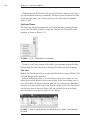
1. To open Revit Architecture, click the icon on your desktop (see
Figure 1.1), or choose Start ➣ All Programs ➣ Revit Architecture
2010 (see Figure 1.2).
F i g u r e 1 . 1 : You can launch Revit Architecture from the desktop icon.
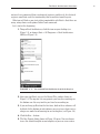
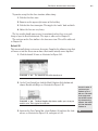
2. After you start Revit, you see the Recent Files window shown in
Figure 1.3. The top row lists any projects you have been working on;
the bottom row lists any families you have been working on.
3. If you are firing up Revit for the first time, both of these columns will
be blank. At the bottom of each column, you are given a choice of creating a new model or of browsing for an existing one (see Figure 1.4).
4. Click the New… button.
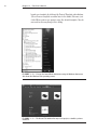
5. The New Project dialog shown in Figure 1.5 opens. You can choose
to use the default template or no template, or you can even create a
3
4
C hapter 1 • The Revit World
brand-new template by clicking the Project Template radio button.
(We will cover template creation later in the book.) For now, just
click OK to create a new project using the default template. You do
not need to alter anything in this dialog.
F i g u r e 1 . 2 : You can also launch Revit Architecture using the Windows Start menu
(this shows the Windows Vista operating system).
F i g u r e 1 . 3 : The Recent Files window lists any recent projects or families you have
worked on.
The Revit Architecture Interface
F i g u r e 1 . 4 : You can create a new model or browse for an existing one.
F i g u r e 1 . 5 : The New Project dialog allows you to start a new project using a
preexisting template file, or you can create a new template file.
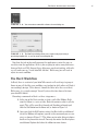
Now that the task of physically opening the application is out of the way, we
can delve into the application. At first, you are going to notice many differences
between Revit and CAD. Some of these differences may be off-putting, while others will make you say “I wish AutoCAD did that.” Either way, you will need to
adjust to a new workflow.
The Revit Workflow
In Revit, there is certain feel you AutoCAD converts will need to get a grasp of.
Some of you will find this new workflow easy to adapt to while others will find it
excruciatingly foreign. (To be honest, I found the latter to be the case at first.)
Either way, it is a simple concept. You will just need to slow down a bit from
your AutoCAD habits.
Executing a command in Revit is a three-step process:
1. At the top of the Revit window is what is called the Ribbon. Built
into the ribbon is a series of tabs. Each tab contains what is called a
panel. This will be your Revit launch pad! Speaking of launch pad,
click the Wall button on the Home tab, as shown in Figure 1.6.
2. Once you click the Wall button, notice that Revit adds an additional
tab to the Ribbon with options specific to the command you are running, as shown in Figure 1.7. This allows you to make different choices
based on the placement of a wall. You may also notice that Revit places
an additional Options bar below the ribbon for more choices.
5
C hapter 1 • The Revit World
6
F i g u r e 1 . 6 : The Design bar is the backbone of Revit Structure.
F i g u r e 1 . 7 : The Options bar replaces the command prompt from
AutoCAD. MicroStation users will be more familiar with this method.
You will hear this
throughout the
book: always
remember to look
at your options.
With no command
prompt, the Options
bar will be one of
your few guides.
3. Once you have made your choices from the Ribbon and the Options
bar, you can place the object into the view window. This is the large
“drawing area” that takes up two thirds of the Revit interface. To
place the wall, simply pick a point in the window and move your
pointer. The wall starts to form. You can press the Esc key to exit
the command.
Using Revit is not generally as easy as this, but keep in mind this basic threestep process:
1. Start a command.
2. Choose an option from the appropriate tab.
3. Place the item in the view.
Revit appears to offer a fraction of the choices and functionality that AutoCAD
or any drafting program offers. This is true in a way. Revit does offer much fewer
choices to start a command, but how many choices does an architect or an architectural designer need? Revit keeps its functionality focused on architecture and
construction. It is the dynamic capabilities of the application during the placement of the items, as well as the functionality of the objects after they have been
placed in the model that gives Revit its robust capabilities. Never judge a book by
its cover — unless, of course, it is the book you are reading right now.
Let’s keep going with the main focus of the Revit interface. This is the Ribbon.
You will be using the Ribbon exclusively within Revit.
The Revit Architecture Interface
The Ribbon
You will be using the Ribbon for all of the commands you execute in Revit. As you
can see, you don’t have much of a choice to do otherwise. However, this is good,
because it narrows your attention to what is right in front of you. When you pick
an icon on the Ribbon, Revit will react to that with a new tab giving you the specific additional commands and Options you need. In addition, Revit also keeps
the existing tabs that can help you while you are in the current command, as
shown in Figure 1.8. Again, the focus here is to keep your eyes in one place.
In this book, there will be a few terms thrown at you that you will become
familiar with. Of course we just discussed the Ribbon, but mostly you will be
directed to choose a tab, and to find a panel on that tab.
To keep the example familiar, when you selected the wall button, your instructions will read: “On the Build panel of the Home tab, click the Wall button.”
F i g u r e 1 . 8 T he Ribbon breakdown.
W h at ’ s T h at T o o l b a r A b ov e T h e R i b b o n ?
This toolbar is called the Quick Access toolbar. It is filled with some popular
commands. One special function of this toolbar is the cursor icon. You are
to use this button when you wish to terminate a command. To the left of
this toolbar is what we are calling the Revit Home button. By clicking this
button, you have access to more Revit functions that will be covered later
in the book.
7
8
C hapter 1 • The Revit World
Now that you are starting to see how the ribbons and the tabs flow together,
let’s take a look at another feature within the Ribbon panels that allows you to
reach beyond the immediate Revit interface.
The Change Element Type Menu
When you pick the wall button, an entirely new set of commands appears. What
you will immediately notice is that there is a picture of the item you are placing
in the model (in this case it’s a wall). Below that picture is a menu that says
“Change Element Type.” Once you click this menu, you will see that there is an
entire list of additional walls to choose from, as shown in Figure 1.9.
F i g u r e 1 . 9 T he Change Element Type Menu
The objective of the next exercise is to start placing walls into the model:
1. Open Revit Architecture using the default template.
2. On the Home tab, click the Wall button.
3. In the Change Element Type menu, select Exterior - Brick and CMU
on MTL. Stud.
4. On the far left side of the Element panel is the Element Properties
button, shown in Figure 1.10. Click this button.
The Revit Architecture Interface
F i g u r e 1 . 1 0 : The Element Properties button gives you access to many
variables associated with the item you are adding to the model.
Clicking the Element Properties button provides you with a new world of choices
and options. You will soon see that the power of Revit is hiding just below the surface.
Element Properties
Hidden within the Options bar is a single button that will gain you access to a
multitude of choices and parameters. Although this dialog will contain different
information for each item, the format will stay the same. One of the many wonders of Revit Architecture is the fact that most procedures, dialogs, and processes
are virtually the same as the next. Master how to build a wall, and you have
mastered how to build a roof and a floor.
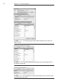
Within the element properties you will see two categories, as shown in
Figure 1.11. In this figure, the first category, Type Parameters, is grayed out,
and you cannot select anything. In the other category, Instance Parameters,
you can edit settings directly. There is a huge difference between the two.
Instance Parameters
The items that can be immediately edited are called instance parameters. This
means that these parameters will change only the object being added to the
model at this time. Also, if you select an item that has already been placed in the
model and click the Element Properties button, the instance parameters will
change only that item you have selected. This makes sense — not all items are
built equally in the real world. Figure 1.12 illustrates the instance parameters of
a typical wall.
Type Parameters
The type parameters (see Figure 1.13), when edited, will alter every item of that
type in the entire model. To access the type parameters, click the Edit Type button while still in the Element Properties dialog, as Figure 11.14 shows.
9
10
C hapter 1 • The Revit World
F i g u r e 1 . 1 1 : The element properties hold a wealth of parameters and control over
families in Revit.
F i g u r e 1 . 1 2 : The instance parameters will change only the currently placed item or
the currently selected item.
F i g u r e 1 . 1 3 : The type parameters, when modified, will alter every occurrence of this
specific wall in the entire model.
The Revit Architecture Interface
F i g u r e 1 . 1 4 : The Edit Type button allows you to access the type parameters.
At this point, you have one of two choices. You can either make a new wall
type (leaving this specific wall unmodified) by clicking the Duplicate button, or
you can start editing the wall’s type properties, as shown in Figure 1.15.
W a r n i n g I cannot stress enough that if you start modifying type
properties without duplicating the type, you need to do so in a very deliberate manner. You can easily affect the model in an unintended manner. We
will discuss the specifics of all of the wall’s type parameters in Chapter 16,
“Advanced Wall Topics.”
F i g u r e 1 . 1 5 : The type parameters are used to modify the wall system’s global settings.
11
12
C hapter 1 • The Revit World
Now that you have gained experience with the Element Properties dialog, it
is time to go back and study the rest of the Options bar as it pertains to placing a wall:
1. Since we are only exploring the element properties, click the Cancel
button twice to return to the model.
2. Back in the Options bar, find the Location Line: menu. This will allow
you to set the wall justification. Select Finish Face: Exterior (see
Figure 1.16).
3. On the Options bar, be sure the Chain checkbox is selected, as
Figure 1.16 shows. This will allow you to draw the walls continuously.
F i g u r e 1 . 1 6 : By selecting Finish Face: Exterior, you know the wall will
be dimensioned from the outside finish.
4. In the Draw panel, there is a series of “sketch” options. Since this specific wall is straight, make sure the Line button is selected, as shown
in Figure 1.17.
F i g u r e 1 . 1 7 : You can draw basically any shape you need.
Get used to studying the Ribbon and the Options bars — it is going to be your
crutch as you start using Revit Architecture! Of course, at some point you need
to physically start placing items in the model. This is where the view window
comes into play.
The Revit Architecture Interface
The View Window
To put it simply, the big white area where the objects go is the view window. As a
result of your actions, this area will become populated with your model. Notice
the background is white — this is because the sheets you plot on are white. In
Revit, what you see is what you get … literally. In Revit, you aren’t counting on
color #5, which is blue, for example, to be a specific line width when you plot.
You will be able to see immediately what the thickness of all of your “lines” are
going to be before you plot. What a novel idea. See Figure 1.18.
F i g u r e 1 . 1 8 : The view window collects the results of your actions.
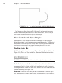
To continue placing some walls in the model, keep going with the exercise. If
you have not been following along, you can start by clicking the Wall button on
the Home tab. In the Change Element Type menu, select Exterior - Brick and
CMU on MTL. Stud. Make sure that the wall is justified to the finish face exterior. You may now proceed:
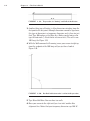
1. With the Wall command still running and the correct wall type
selected, position your cursor in a similar location to the illustration
in Figure 1.19. Now, pick a point in the view window.
2. With the first point picked, move your cursor to the left. You will
notice that a few things are happening. One is that the wall seems to
be snapping in a horizontal plane, and there is a blue dashed line that
apparently locks the horizontal position. In Revit, there is no “Ortho.”
Revit will align the typical compass increments 0, 90, 180, 270, and
45 degrees.
13
14
C hapter 1 • The Revit World
F i g u r e 1 . 1 9 : The procedure for “drawing” a wall in Revit Architecture
3. Another thing you will notice is a blue dimension extending from the
first point to the last point. Although dimensions cannot be typed over,
this type of dimension is a temporary dimension, and is there for just
that. Type 100, and press the Enter key. (Notice you did not need to
type the foot mark ('). Revit thinks in terms of feet.) The wall is now
100' long. See Figure 1.19.
4. With the Wall command still running, move your cursor straight up
from the endpoint of the 100'-long wall you just drew. Look at
Figure 1.20.
F i g u r e 1 . 2 0 : How Revit Architecture works is evident in this procedure.
5. Type 80 and hit Enter. You now have two walls.
6. Move your cursor to the right until you “run into” another blue
alignment line. Notice that your temporary dimension says 100'–0".
The Revit Architecture Interface
Revit understands symmetry. Once you see this alignment line, and
the temporary dimension says 100'–0", pick this point.
7. Move your cursor straight down and type 16.
8. Move your cursor to the right and type 16.
9. Hit the Esc key.
Do your walls look like Figure 1.21? If not, try it again. You need to be able to
do this and to be comfortable with this procedure (as much as possible).
F i g u r e 1 . 2 1 : Working with Revit starts with the ability to work with the view window,
and learning the quirks and the feel of the interface.
To get used to the Revit flow, always remember these three steps:
1. Start a command.
2. Focus on your options.
3. Move to the view window, and add the elements to the model.
If you start a command, then focus immediately on the view, you will be sitting
there wondering what to do next. Do not forget to check your options and the
appropriate ribbon tab.
Let’s keep going and close this building by using a few familiar commands. If
you have never drafted on a computer before, don’t worry. These commands are
simple. Starting with the easiest but most important is the topic of being able to
simply select an object.
15
16
C hapter 1 • The Revit World
Object Selection
Revit has a few similarities to AutoCAD and MicroStation. One of those similarities is the ability to perform simple object selection, and to be able to execute
common modify commands. For this example, we are going to mirror the two
16'–0" L-shaped walls to the bottom of the building:
1. Type ZA (zoom all).
2. Click the Modify button on the Design bar.
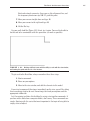
3. Near the two 16'–0" L-shaped walls, pick (left-click) and hold down
the pick button at a point to the right of the walls but below the long,
100'–0" horizontal wall.
4. You will see a window start to form. Run that window past the two
walls. Once they are highlighted, as illustrated in Figure 1.22, let go
of the pick button, and the walls are selected.
F i g u r e 1 . 2 2 : Picking a “crossing” window to select two walls
There are two ways to select an object: by using a crossing window or by using
a box. Each plays an important role in how you select items in a model.
Crossing Windows
In Revit, you can select items in one of two ways. A crossing window describes
an object selection method in which the window being placed only needs to
cross through the objects in order for them to become selected. A crossing window will always start from the right and end to the left. The crossing window,
when being placed, is represented by a dashed-line composition (see Figure 1.22).
The Revit Architecture Interface
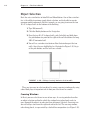
Boxes
A box is an object selection method that will only select the items that are 100
percent inside the window being placed. This method is useful when you want to
select only specific items while passing through larger objects that you may not
want in the selection set. A box always starts from the left and works to the
right. The line type is a continuous line (see Figure 1.23).
F i g u r e 1 . 2 3 : To select only objects that are surrounded by the window, select a box.
This will leave out any item that may only be partially within the box.
Now that you have experience selecting items, you can execute some basic
modify commands. Let’s begin with mirroring, one of the most popular modify
commands.
Modifying and Mirroring
You will find that Revit Architecture requires that you select items first, and
then execute a command. This is true for most action items, and is certainly
true for every command on the Modify toolbar.
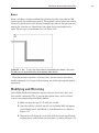
1. Make sure only the two 16'–0" walls are selected.
2. Once the walls are selected, you will see the Modify Walls tab appear.
On the Modify panel, click Mirror ➣ Draw Mirror Axis, as shown in
Figure 1.24.
3. Your cursor will change to a cross hair with the mirror icon illustrating that you are ready to draw a mirror plane, as shown in Figure 1.25.
17
18
C hapter 1 • The Revit World
F i g u r e 1 . 2 4 : The Ribbon adds the appropriate commands.
F i g u r e 1 . 2 5 : There are options you will have to choose for every
command in Revit.
4. Make sure the Copy checkbox is selected (see Figure 1.25).
5. Hover your cursor over the inside face of the 80'–0"-long vertical wall
until you get to the midpoint. Revit will display a triangular icon, indicating that you have found the midpoint of the wall. See Figure 1.26.
F i g u r e 1 . 2 6 : Revit has snaps similar to most CAD applications. In Revit,
you will only get snaps if you choose the draw icon from the Options bar during a
command.
6. Once the triangular midpoint snap appears, pick this point. Once
you pick the point where the triangle appears, you can move your
cursor directly to the right of the wall. You will see an alignment
The Revit Architecture Interface
line appear, as illustrated in Figure 1.27. Once the alignment line
appears, you can pick another point along the path. Once you pick
the second point, the walls are mirrored and joined with the south
wall. Again, refer to Figure 1.27.
F i g u r e 1 . 2 7 : Mirroring these walls will involve first, picking the midpoint
of the vertical wall, then second, picking a horizontal point along the plane.
Now that you have some experience mirroring items, it is time to start adding
components to your model by utilizing the items that have been placed previously.
If you are not getting it, retry these first few procedures. Rome was not built in a
day. (Well, perhaps if they had Revit, it would have sped things up!) You want
your first few walls to look like Figure 1.28.
F i g u r e 1 . 2 8 : Your building should look like this illustration.
19
20
C hapter 1 • The Revit World
Building on Existing Geometry
Now that you have some geometry to work with and you have some objects
placed in your model, Revit starts to come alive. The benefits of using building
information modeling (BIM) will become apparent quickly, as explained later in
this chapter. For example, because of the fact that Revit knows that walls are
walls, you can add identical geometry to the model by simply selecting an item
and telling Revit to create a similar item.
Suppose you wanted a radial wall of the same exact type of the other walls in
the model. Perform the following steps:
1. Type ZA to zoom the entire screen.
2. Press the Esc key.
3. Select one of the walls in the model — it does not matter which one.
4. Right-click on the wall.
5. Select Create Similar, as shown in Figure 1.29.
F i g u r e 1 . 2 9 : You can select any item in Revit and create a similar object
by right-clicking and selecting Create Similar.
6. On the Place Wall tab, click the Start-End-Midpoint Arc button, as
shown in Figure 1.30.
The Revit Architecture Interface
F i g u r e 1 . 3 0 : Just because you started the command from the view
window does not mean you do not have to look at your options.
7. Again with the Options? Yes. Make sure your Location Line: is set to
Finish Face Exterior.
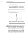
8. With your wheel button on your mouse, zoom into the upper corner
of the building and select the top endpoint of the wall, as shown in
Figure 1.31. The point you are picking is the corner of the heavy
lines. The topmost, thinner line actually represents a concrete belt
course below.
F i g u r e 1 . 3 1 : Select the top corner of the wall to start your new
radial wall.
9. Select the opposite, outside corner of the bottom wall.
10. Move your cursor to the right until you see the curved wall pause.
You will also see an alignment line and a tangent snap icon appear as
well. Revit understands that perhaps you want an arc tangent upon
the two lines you have already placed in your model.
11. Once you see this, pick the third point. Your walls should look like
Figure 1.32.
21
22
C hapter 1 • The Revit World
F i g u r e 1 . 3 2 : The completed exterior walls should look like this illustration.
Just because you have placed a wall in the model, that does not necessarily
mean it looks the way you would like. In Revit Architecture, there is a lot you
can do with view control and how objects are displayed.
View Control and Object Display
Although this is a nice way to add walls to a drawing, it does not reflect the
detail you are going to need to produce construction documents. Well, the great
thing about Revit is that you have already done everything you need to do. You
can now tell Revit to display the graphics the way you want to see them.
The View Control Bar
At the bottom of the view window, you will see a skinny toolbar (as illustrated in
Figure 1.33). This is the View Control bar. It contains the following functions:
F i g u r e 1 . 3 3 : The View Control bar controls the graphical view of your model.
Scale The first item on the View Control bar is the scale function. It gets small
mention here, but it is a huge deal. In Revit, you change the scale of a view by
selecting this menu. Change the scale here, and Revit will scale annotations and
symbols accordingly. See Figure 1.34.
Detail Level The detail level allows you to view your model at different qualities. You have three to choose from: Coarse, Medium, and Fine. See Figure 1.35.
The Revit Architecture Interface
F i g u r e 1 . 3 4 : The scale menu allows you to change the scale of your view.
F i g u r e 1 . 3 5 : The detail level control allows you to set different view levels for the
current view.
If you want this view to appear with more graphical information you would
select the Fine choice. To see how the view is adjusted using this control, follow
these steps:
1. Select the detail level icon and choose Fine.
2. Zoom in on a wall corner. Notice the wall components are now
showing in the view.
23
24
C hapter 1 • The Revit World
T i p When you change the view control in a view, it is not a temporary
display. You are telling Revit how you want to plot this view. If you see it on
the screen, you will see it when it comes out of the plotter.
There are other items on the View Control bar, but we’ll discuss them when
they become applicable to the exercises.
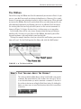
The View Tab
Since Revit is one big happy model, you will quickly find that simply viewing
the model will become quite important. Within Revit, there is some functionality
that you can take advantage of in the form of the Navigation bar. To activate the
Navigation bar, first go to the view tab, then click the User Interface button. Make
sure the Navigation bar is activated, as shown in Figure 1.36.
One item we need to look at on the Navigation bar is the steering wheel.
F i g u r e 1 . 3 6 : The View tab produces the Navigation bar.
The Steering Wheel
The steering wheel, allows you to zoom, rewind, and pan. When you pick the
steering wheel icon, a larger control “panel” will appear in the view window. To
choose one of the options, you simply pick (left-click) one of the options, and
hold the pick button as you execute the maneuver.
The Revit Architecture Interface
To use the steering wheel, follow along:
1. Pick the steering wheel icon from the Navigation bar, as shown in
Figure 1.37.
2. Once the steering wheel is in the view window (as illustrated in
Figure 1.37), click (left-click) and hold the Zoom choice. You can
now zoom in and out.
F i g u r e 1 . 3 7 : You can use the steering wheel to navigate through a view.
3. Now click and hold the Rewind choice in the steering wheel. You can
now find an older view, as shown in Figure 1.38.
F i g u r e 1 . 3 8 : Because of the fact that Revit does not include zoom
commands in the Undo function, you can rewind to find previous views.
4. Do the same for the Pan choice. The Pan function is found on the
outer ring of the steering wheel. Once you press and hold Pan, you
can navigate to other parts of the model.
25
26
C hapter 1 • The Revit World
Although you can do all of this with your wheel button, some users still prefer
the icon method of panning and zooming. For those of you who prefer the icons
for the previous items, you will also want to use the icons for the traditional
zooms as well.
Traditional Zooms
The next items on the Navigation bar are the good old zoom controls that you
are used to. The ability to zoom in, zoom out, and pan are all included in this
function, as shown in Figure 1.39.
F i g u r e 1 . 3 9 : The standard zoom commands
Of course, if you have a mouse with a wheel, you can zoom and pan by either
holding down the wheel to pan or by wheeling the button to scroll in and out.
Thin Lines
Back on the View tab, you will see an icon called thin lines, as shown in Figure 1.40.
Let’s talk about what this icon does.
In Revit Architecture, there is no such thing as layers. Line weights are controlled by the actual objects they are representing. In the view window, you see
these line weights. As mentioned before, what you see is what you get. Sometimes,
however, these line weights may be too thick for smaller-scale views. By clicking
the thin lines icon as shown in Figure 1.40, you can force the view to display
only the thinnest lines possible to still see the objects.
F i g u r e 1 . 4 0 : Using the thin lines icon will allow you to “operate” on the finer items
in a model.
The Revit Architecture Interface
27
To practice using the thin lines function, follow along:
1. Pick the thin lines icon.
2. Zoom in on the upper-right corner of the building.
3. Pick the thin lines icon again. This toggles the “mode” back and forth.
4. Notice the lines are very heavy.
The line weight should concern you. As mentioned earlier, there is no such
thing as layers in Revit Architecture. This topic is addressed in Chapter 13.
The next icon on the View toolbar is the show mass icon. This will be addressed
in Chapter 16.
Default 3D
This icon actually brings us to a new discussion. Complete the following steps that
will move us into the discussion on how a Revit model actually comes together!
1. Click the default 3D icon, as illustrated in Figure 1.41.
F i g u r e 1 . 4 1 : The default 3D icon will be heavily used.
2. On the View Control bar, click the Model Graphics Style button and
choose Shaded with Edges, as illustrated in Figure 1.42.
F i g u r e 1 . 4 2 : The Model Graphics Style button enables you to view your
model in color. This is typical for a 3D view.
3. Again on the View Control bar, select Shadows Off and turn the shadows on, as illustrated in Figure 1.43, and again in 1.45.
A word of caution: if
you do turn your
shadows on, do so
with care. This could
be the single worst
item in Revit in terms
of performance degradation. Your model
will slow down with
shadows on.
28
C hapter 1 • The Revit World
F i g u r e 1 . 4 3 : Shadows create a nice effect, but at the expense of RAM.
Within the 3D view is the ViewCube. It is the cube in the upper-right corner
of the view window. You can switch to different perspectives of the model by
picking on the quadrants of the cube (see Figure 1.44).
F i g u r e 1 . 4 4 : The ViewCube lets you freely look at different sides of the building.
T i p The best way to navigate a 3D view is to press and hold the Ctrl key
on the keyboard. As you are holding down the Ctrl key, press and hold the
zoom wheel on your mouse. Now move the mouse around. You will be able to
dynamically view the model.
F i g u r e 1 . 4 5 : The 3D model with shading and shadows.
Go back to the floor plan. Wait! How? This brings us to quite an important
topic in Revit: the Project Browser.
The Project Browser
The Project Browser
Revit is the frontrunner of BIM. BIM is sweeping our industry for a reason. One of
the biggest reasons is the fact that you have a fully integrated model right in front
of you. What this means is that when you need to open a different floor plan, elevation, detail, drawing sheet, or 3D view, you can find it all right here in the model.
Also, this means our workflow is going to change. In most cases, it is going to
change drastically. When you think about all the external references and convoluted folder structures that comprise a typical job, you can start to relate it to
the way Revit uses the Project Browser. Within Revit, you are using the Project
Browser instead of the folder structure previously used in CAD.
This changes the playing field. With CAD, the process of closing the file you
are in and opening the files you need to work on is restructured in Revit to enable
you to stay in the model. You never have to leave one file to open another. You
also never need to rely on external referencing to complete a set of drawings.
Revit and the Project Browser will put it all right in front of you.
To start using the Project Browser, follow along:
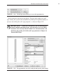
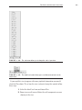
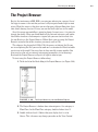
1. To the far left of the Revit dialog is the Project Browser (see Figure 1.46).
F i g u r e 1 . 4 6 : The Project Browser is your new Windows Explorer.
2. The Project Browser is broken down into categories. One category is
Floor Plans. In the Floor Plans category, double-click on Level 1.
3. Double-click on Level 2. Notice that your display level is set to
Coarse. This is because any change you make on the View Control
29
30
C hapter 1 • The Revit World
bar is for that view only. When you went to Level 2 for the first time,
that change has not been made yet.
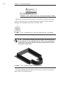
4. In the view window, you will see little icons that look like houses (see
Figure 1.47). These are elevation markers. The elevation marker to
the right might be in your building. If this is the case, you need to
move it out of the way.
5. Pick a box around the elevation marker. Once both the small triangle
and the small box are selected, move your mouse over the selected
objects.
6. Your cursor will turn into a move icon. Pick a point on the screen and
move the elevation marker out of the way.
F i g u r e 1 . 4 7 : Elevation markers are shown in plan as these symbols. If
you are to move them, it must be done by picking a window. There are two actual
items in an elevation marker.
W A r n i n g Hey! What happened to my elevation? You are in Revit
now. Items such as elevation markers, section markers, and callouts are no
longer just “dumb” blocks. They are linked to the actual view they are calling
out. If you delete one of these markers, you will delete the view associated
with it. If it is a view that you and your design team has been working on,
you lost that view. Also, if you move an item it needs to be done deliberately
and with caution. This elevation marker you moved has two parts. The little
triangle is actually the elevation. The little box is the part of the marker that
records the sheet number the elevation will wind up on. If you do not move
both items by placing a window around them, it will leave the elevation’s
origin where it was. Once this happens, your elevation will look like a section, and it will be hard to determine what happened.
The Project Browser
7. In the Project Browser, find the Elevations (Building Elevations) category. Double-click on South.
8. Also in the Project Browser, notice there is a 3D category. Expand the
3D category, and double-click on the {3D} choice. This will bring you
back to the 3D view you were looking at previous to this exercise.
Now that you can navigate through the Project Browser, adding other components to the model will be much easier. To start with, we can begin to add some
windows.
Windows
By clicking on all of these views, you are simply opening a view of the building,
not another file that is stored somewhere. For some users this can be confusing.
(It was for me.)
When you click around and open all of these views, they stay open. You can
quickly open many views. There is a way to manage these views before it gets
out of hand.
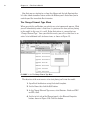
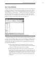
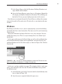
In the upper-right corner of the Revit dialog, you will see the traditional close
and minimize/maximize buttons for the application. Just below them are the
traditional buttons for the files that are open, as shown in Figure 1.48. Click the
X for the file.
F i g u r e 1 . 4 8 : You can close a view by clicking the X for the view. This does not close
Revit, or an actual file for that matter — it simply closes that view.
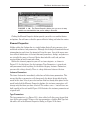
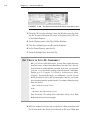
In this case, you have multiple views open. This situation (which is quite common) is best managed on the View tab. To utilize the Window menu, perform
the following steps:
1. On the Windows panel of the View tab, click the Switch Windows button, as shown in Figure 1.49.
2. Once the menu is expanded, look at the open views.
31
32
C hapter 1 • The Revit World
F i g u r e 1 . 4 9 : The Window menu lists all the current views that are open.
3. Go to the {3D} view by selecting it from the Window menu, by clicking the 3D icon at the top of the screen, or by going to the {3D} view
in the Project Browser.
4. On the Windows panel, click Close Hidden Windows.
5. Close this window by pressing Esc on the keyboard.
6. In the Project Browser, open Level 1.
7. Go to the Window Panel and select Tile.
B u t I U s e d t o T y p e M y C o mm a n d s !
Well, you still can. In the Revit menus, you may have noticed that many
items have a two- or three-letter abbreviation to the right. This is the keyboard shortcut associated with the command. If you want, you can make
your own, or you can modify existing keyboard shortcuts. In Windows
Explorer, go to C:\Program Files\Revit Architecture 2010\
Program\ KeyboardShortcuts.txt. Within this .txt file, you can
find the shortcut you wish to add. By removing the semicolon, you can put
your shortcut between the quotation marks. For example, change the string
that looks like this:
menu:”Window-Arrange Icons”
to this:
“WA”menu:”Window-Arrange Icons”
Save the text file. The setting will not take effect until you close Revit
Architecture and open it back up again.
8. With the windows tiled, you can see the Level 1 floor plan along with
the 3D view to the side. Select one of the walls in the Level 1 floor plan.
F i l e Ty p e s a n d Fa m i l i e s
Notice it is now selected in the 3D view to the side. These views you
have open are mere representations of the model from that perspective.
Each view of the model can have its own independent view settings.
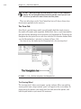
You are at a good point now to save the file. And this brings the book to a good
point to discuss the different file types, and their association to the BIM model.
File Types and Families
Revit Architecture has a somewhat unique way in which it saves files and utilizes different file types to build a BIM model. To learn how and why Revit has
chosen these methods, follow along with these steps.
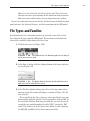
1. Click the save icon (see Figure 1.50).
F i g u r e 1 . 5 0 : The traditional save icon will bring up the Save As dialog if
the file has never been saved.
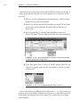
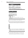
2. In the Save As dialog, click the Options button in the lower-right corner (see Figure 1.51).
F i g u r e 1 . 5 1 : The Options button in the Save As dialog will allow you to
make some choices in how the file is saved.
3. In the File Save Options dialog, you will see at the top a place where
you can specify the number of backups, as shown in Figure 1.52. Set
this value to 1.
The reason Revit does this is because, when you click the save icon,
Revit actually duplicates the file. It will simply add a suffix of “001” to
the end of the filename. Each time you click the save icon, Revit will
record this save and add another file called “002,” leaving the “001”
intact. The default is to do this three times before it starts replacing
the 001, 002, and 003 with the three most current files.
33
34
C hapter 1 • The Revit World
4. Under the Preview section, you can specify which view this file will be
previewed in. I like to keep it as the current view. That way, I can get
an idea if the file is up-to-date based on the state of the view. Click OK.
F i g u r e 1 . 5 2 : The Options in the Save As function allow you to specify
number of backups as well as the view it will use for the preview.
5. Create a folder somewhere, and save this file into the folder. The name
of the file used as an example in the book is called NER.rvt. (NER
stands for “No Experience Required.”) Of course, you can name the
file anything you wish, or you can even just do your own project
using the steps and examples from the book as a guideline.
Now that you have experience adding components to the model, it is time to
investigate exactly what it is we are adding here. Each component is a member
of what Revit calls a family.
U n d e r s ta n d i n g t h e R e v i t A r c h i t e c t u r e F i l e (.rvt)
The extension for a Revit Architecture file is .rvt. There are three separate
Revit applications: Revit Architecture, Revit Structure, and Revit MEP. All
three Revits share the same .rvt file extension. You can open a Revit file
produced in any of these three applications directly. You do not need object
enablers to read items that do not pertain to that discipline.
F i l e Ty p e s a n d Fa m i l i e s
System and Hosted Families (.rfa)
As mentioned earlier, a Revit model is based on a compilation of items called
families. There are two types of families: system families and hosted families. A
system family can only be found within a Revit model and cannot be stored in a
separate location. A hosted family is inserted similar to a block (or cell) and is
stored in an external directory. The file extension for a hosted family is .rfa.
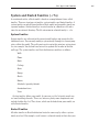
System Families
System families are inherent to the current model and are not inserted in the
traditional sense. You can only modify a system family through its element properties within the model. The walls you’ve put in up to this point are system families, for example. You did not have to insert a separate file in order to find the
wall type. The system families in a Revit Architecture model are as follows:
Walls
Floors
Roofs
Ceilings
Stairs
Ramps
Shafts
Rooms
Schedules/quantity takeoffs
Annotation items
Views
System families define your model. As you can see, the list pretty much covers most building elements. There are, however, plenty more components not
included within this list. These items, which can be loaded into your model, are
called hosted families.
Hosted Families
All other families in Revit Architecture hosted in some way by either a system
family or a level. For example, a wall sconce is a hosted family in that, when you
35
36
C hapter 1 • The Revit World
insert it, it will be appended to a wall. Hosted families carry a file extension of
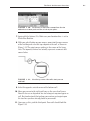
.rfa. To insert a hosted family into a model, follow these steps:
1. Open the NER.rvt file or your own file.
2. Go to Level 1.
3. On the Home tab, select the Door button.
4. On the Place Door tab, click the Load family button, as shown in
Figure 1.53.
F i g u r e 1 . 5 3 : You can load an RFA file during the placement of a
hosted family.
5. Browse to the Doors directory.
(Note that if you are on a network, your directories may not be the
same as in this book. Contact your CAD/BIM manager (or whoever
loaded Revit on your computer) to find exactly where they may have
mapped Revit.
6. Notice there is a list of doors. Select Single-Raised Panel with
Sidelights.rfa, and click Open.
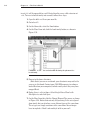
7. On the Place Door tab, click the Change Element Type menu, as shown
in Figure 1.54. Notice that not only did you bring in the raised panel
door family, but you also have seven different types of the same door.
These types are simply variations of the same door. You no longer
have to explode a “block” and modify it to fit in your wall.
F i l e Ty p e s a n d Fa m i l i e s
F i g u r e 1 . 5 4 : Each family .rfa file will contain multiple types
associated with that family.
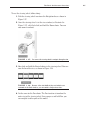
8. Zoom in on the upper-left corner of the building as illustrated in
Figure 1.55.
9. To insert the door into the model, you must place it in the wall.
(Notice that before you hover your cursor over the actual wall, Revit
will not allow you to add it to the model, as shown in Figure 1.55.)
Once your pointer is directly on top of the wall, you will see the outline of the door. Once you see this, pick a point in the wall. The door
is inserted. (We will cover this in-depth in the next chapter.)
F i g u r e 1 . 5 5 : Inserting a hosted family (.rfa)
37
38
C hapter 1 • The Revit World
You will be using this method quite a bit in this book and on a daily basis
when you use Revit. One thing to note is the fact that when a family is loaded
into Revit Architecture, there is no live path back to the file that was loaded.
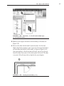
Once it is added to the Revit model, it becomes part of that model. To view a list
of the families that are within the Revit model, go to the Project Browser and
look for the Families category. Within the Families category, you will see a list
of the families and their types, as Figure 1.56 shows.
F i g u r e 1 . 5 6 : All of the families as listed in the Project Browser
The two main Revit files have been addressed. Two others are still crucial to
the development of a Revit model.
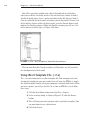
Using Revit Template File (.rte)
The .rte extension pertains to a Revit template file. Your company surely has
developed a template for your own standards or will soon. An RTE file is simply
the default template that has all of your companies standards built into it. When
you start a project, you will use this file. To see how an RTE file is used, follow
these steps:
1. Click the Revit Home button and select New ➣ Project.
2. In the resulting dialog, as shown in Figure 1.57, click the Browse
button.
3. This will throw you into a category with several other templates. You
can now choose to use a different one.
4. Click Cancel twice.
F i l e Ty p e s a n d Fa m i l i e s
F i g u r e 1 . 5 7 : A new Revit model is based on an RTE template file.
Whenever you start a project, this is the type of template you are going to use.
When you are starting a new family, however, you will want to use an RFA.
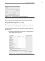
Using Revit Family Files (.rft)
The .rft extension is another type of template, only this one pertains to a family template. It would be nice if Revit had every family fully developed to suit
your needs. Alas, it does not. You will have to develop your own families. You
will start with a family template. To see how to access a family template, perform these steps:
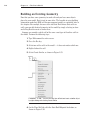
1. Click the Revit Home button, and select New ➣ Family to open the
browse dialog shown in Figure 1.58.
F i g u r e 1 . 5 8 : The creation of a family starts with these templates.
39
40
C hapter 1 • The Revit World
2. Browse through these templates. You will most certainly use many
of them.
3. Click the Cancel button.
Tempting? I know! We will thoroughly cover creating in Chapter 17, “Families.”
As mentioned earlier, you are only going to get to a certain point before you run
out of Revit provided content. If you are feeling brave, go ahead and play around
in one of the templates. You have nothing to lose (except time).
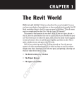
Are You Experienced?
Now You Can…
E Enavigate the Revit Architecture interface and actually start a
model
E Efind commands on the Design bar and understand how this
controls your options
E Efind where to change a keyboard shortcut to be similar to what
you had in CAD
E Enavigate through the Project Browser
E Eunderstand how the Revit interface is broken down into views
E Etell the difference between the two different types of families,
and understand how to build a model using them