1
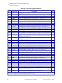
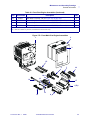
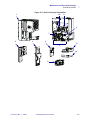
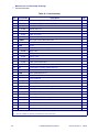
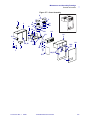
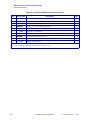
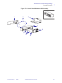
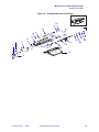
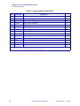
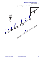
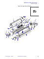
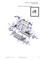
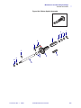
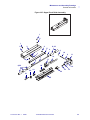
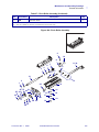
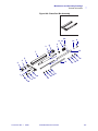
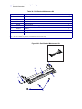
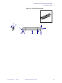
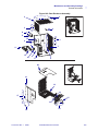
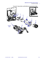
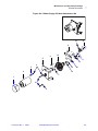
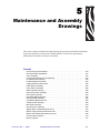
5
Maintenance and Assembly
Drawings
This section contains mechanical assembly drawings and parts lists. Included are illustrations
of parts and assemblies common to all 110PAX4 models, as well as their part numbers.
Maintenance kits and their contents are also listed.
Contents
Front Print Engine Assemblies. . . . . . . . . . . . . . . . . . . . . . . . . . . . . . . . . . . . . . . . . . . .
Rear Print Engine Assemblies . . . . . . . . . . . . . . . . . . . . . . . . . . . . . . . . . . . . . . . . . . . .
Cover Assembly . . . . . . . . . . . . . . . . . . . . . . . . . . . . . . . . . . . . . . . . . . . . . . . . . . . . . . .
Control Panel Maintenance Kit Assembly . . . . . . . . . . . . . . . . . . . . . . . . . . . . . . . . . . .
Print Mechanism Assembly . . . . . . . . . . . . . . . . . . . . . . . . . . . . . . . . . . . . . . . . . . . . . .
Printhead Support Assembly . . . . . . . . . . . . . . . . . . . . . . . . . . . . . . . . . . . . . . . . . . . . .
Toggle Assembly and Pivot Bar . . . . . . . . . . . . . . . . . . . . . . . . . . . . . . . . . . . . . . . . . . .
Upper Dancer Assembly . . . . . . . . . . . . . . . . . . . . . . . . . . . . . . . . . . . . . . . . . . . . . . . .
Lower Dancer Assembly . . . . . . . . . . . . . . . . . . . . . . . . . . . . . . . . . . . . . . . . . . . . . . . .
Ribbon Spindle Assembly . . . . . . . . . . . . . . . . . . . . . . . . . . . . . . . . . . . . . . . . . . . . . . .
Upper Pinch Roller Assembly . . . . . . . . . . . . . . . . . . . . . . . . . . . . . . . . . . . . . . . . . . . .
Pinch Roller Assembly . . . . . . . . . . . . . . . . . . . . . . . . . . . . . . . . . . . . . . . . . . . . . . . . . .
Peel Roller Maintenance Kit. . . . . . . . . . . . . . . . . . . . . . . . . . . . . . . . . . . . . . . . . . . . . .
Platen Peel Bar Assembly . . . . . . . . . . . . . . . . . . . . . . . . . . . . . . . . . . . . . . . . . . . . . . .
Peel Bracket Maintenance Kit . . . . . . . . . . . . . . . . . . . . . . . . . . . . . . . . . . . . . . . . . . . .
Auxiliary Roller Assembly. . . . . . . . . . . . . . . . . . . . . . . . . . . . . . . . . . . . . . . . . . . . . . . .
Idler Roller Assembly . . . . . . . . . . . . . . . . . . . . . . . . . . . . . . . . . . . . . . . . . . . . . . . . . . .
Rear Enclosure Assembly . . . . . . . . . . . . . . . . . . . . . . . . . . . . . . . . . . . . . . . . . . . . . . .
Stepper Motor and Belt Maintenance Kit . . . . . . . . . . . . . . . . . . . . . . . . . . . . . . . . . . . .
Ribbon Supply DC Motor Maintenance Kit. . . . . . . . . . . . . . . . . . . . . . . . . . . . . . . . . . .
Ribbon Take-Up DC Motor Maintenance Kit . . . . . . . . . . . . . . . . . . . . . . . . . . . . . . . . .
Communications Options . . . . . . . . . . . . . . . . . . . . . . . . . . . . . . . . . . . . . . . . . . . . . . . .
Memory Options. . . . . . . . . . . . . . . . . . . . . . . . . . . . . . . . . . . . . . . . . . . . . . . . . . . . . . .
57515L-001 Rev. 1
2/2/05
110PAX4 Maintenance Manual
270
272
274
276
278
280
282
284
286
288
290
292
294
296
298
299
300
302
304
306
308
310
311
267
Maintenance and Assembly Drawings
Notes • ___________________________________________________________________
__________________________________________________________________________
__________________________________________________________________________
__________________________________________________________________________
__________________________________________________________________________
__________________________________________________________________________
__________________________________________________________________________
__________________________________________________________________________
__________________________________________________________________________
__________________________________________________________________________
268
110PAX4 Maintenance Manual
57515L-001 Rev. 1 2/2/05
Maintenance and Assembly Drawings
General Information
General Information
This section identifies parts and assemblies in the 110PAX4 print engine using parts tables and
figures. Both assemblies and parts are listed in the table, and the individual parts are identified
in the associated figure.
In each of the tables, parts shown in bold face can be purchased. Parts shown italicized are not
purchasable, but may be available as a maintenance kit. (This information appears in the key at
the bottom of each parts table.)
Hardware items with an “HW” preceding the part number are not available as individual parts.
You can purchase an item as part of a hardware kit in quantities listed in the parts table.
The parts tables list part numbers for both right-hand (RH) and left-hand (LH) print engines.
All graphics shown in this section are for the right-hand 110PAX4 print engine only.
57515L-001 Rev. 1
2/2/05
110PAX4 Maintenance Manual
269
Maintenance and Assembly Drawings
General Information
Table 16 • Front Print Engine Assemblies
Item
Part Number
Description
Qty
1
57101
Mainframe Assembly, RH
1
1
57102
Mainframe Assembly, LH
1
2
57235M
Front Cover Maintenance Kit, RH (see Figure 177 on page 275)
1
2
57236M
Front Cover Maintenance Kit, LH (see Figure 177 on page 275)
1
3
N/A
Control Panel, RH & LH (see Figure 178 on page 277)
1
4
57200
Print Mechanism Assembly, 203 dpi, RH (see Figure 179 on page 279)
1
4
57230
Print Mechanism Assembly, 203 dpi, LH (see Figure 179 on page 279)
1
4
57210
Print Mechanism Assembly, 300 dpi, RH (see Figure 179 on page 279)
1
4
57240
Print Mechanism Assembly, 300 dpi, LH (see Figure 179 on page 279)
1
5
57201
Printhead Support Assembly, 203 dpi, RH (see Figure 180 on page 281)
1
5
57231
Printhead Support Assembly, 203 dpi, LH (see Figure 180 on page 281)
1
5
57211
Printhead Support Assembly, 300 dpi, RH (see Figure 180 on page 281)
1
5
57241
Printhead Support Assembly, 300 dpi, LH (see Figure 180 on page 281)
1
6
57187M
Toggle Assembly and Pivot Bar Maintenance Kit, RH
(see Figure 181 on page 283)
1
6
57189M
Toggle Assembly and Pivot Bar Maintenance Kit, LH
(see Figure 181 on page 283)
1
7
N/A
Upper Dancer Assembly , RH (see Figure 182 on page 285)
1
7
N/A
Upper Dancer Assembly , LH (see Figure 182 on page 285)
1
8
57531
Lower Dancer Assembly , RH (see Figure 183 on page 287)
1
8
57529
Lower Dancer Assembly , LH (see Figure 183 on page 287)
1
Ribbon Spindle , RH & LH (see Figure 184 on page 289)
1
9
N/A
10
57130
Upper Pinch Roller Assembly, RH (see Figure 185 on page 291)
1
10
57282
Upper Pinch Roller Assembly, LH (see Figure 185 on page 291)
1
11
N/A
Segment Roller , RH & LH
1
12
57130M
Pinch Roller Assembly Maintenance Kit, RH (see Figure 186 on page 293)
1
12
57282M
Pinch Roller Assembly Maintenance Kit, LH (see Figure 186 on page 293)
1
13
43125
Peel Roller Latch Assembly, RH (see Figure 187 on page 295)
1
13
43260
Peel Roller Latch Assembly, LH (see Figure 187 on page 295)
1
14
57131M
Peel Roller Maintenance Kit, RH & LH (see Figure 187 on page 295)
1
15
57058
Platen Peel Bar Assembly, RH (see Figure 188 on page 297)
1
15
57185
Platen Peel Bar Assembly, LH (see Figure 188 on page 297)
1
1
16
N/A
Peel Bracket , RH & LH (see Figure 189 on page 298)
17
57167M
Auxiliary Roller Assembly Maintenance Kit, RH & LH
(see Figure 190 on page 299)
18
57275
Idler Roller Assembly, RH (see Figure 191 on page 301)
1
Bold = Part available for purchase
Italic = Part not available for purchase, listed and shown for reference only
270
110PAX4 Maintenance Manual
57515L-001 Rev. 1 2/2/05
Maintenance and Assembly Drawings
General Information
Table 16 • Front Print Engine Assemblies (Continued)
Item
18
Part Number
57278
Description
Qty
Idler Roller Assembly, LH (see Figure 191 on page 301)
1
19
57600M
300 to 203 dpi Conversion Maintenance Kit, RH & LH (not illustrated)
1
19
57601M
203 to 300 dpi Conversion Maintenance Kit, RH (not illustrated)
1
19
57602M
203 to 300 dpi Conversion Maintenance Kit, LH (not illustrated)
1
Bold = Part available for purchase
Italic = Part not available for purchase, listed and shown for reference only
Figure 175 • Front Main Print Engine Assemblies
2
1
3
15
9
7
18
10,11
12
14
17
4,5,6
16
57515L-001 Rev. 1
2/2/05
13
8
110PAX4 Maintenance Manual
271
Maintenance and Assembly Drawings
General Information
Table 17 • Rear Print Engine Assemblies
Item
Part Number
Description
Qty
1
57087
Rear Enclosure Assembly, RH (see Figure 192 on page 303)
1
1
57088
Rear Enclosure Assembly, LH (see Figure 192 on page 303)
1
2
57272M
AC Power Supply Maintenance Kit, RH & LH
1
3
57330M
Main Logic Board Maintenance Kit, RH & LH
1
4
57056M
Applicator Interface Board Maintenance Kit, 5V I/O
1
4
57389M
Applicator Interface Board Maintenance Kit, 24-28V I/O
1
5
57527M
Stepper Motor Assembly Maintenance Kit, (see Figure 193 on page 305)
1
6
57604M
Stepper Motor Pulley and Belt Maintenance Kit, (203 dpi)
1
6
57464M
Stepper Motor Pulley and Belt Maintenance Kit, (300 dpi)
1
7
57069M
Compound Pulley and Belt Maintenance Kit, RH & LH
1
8
57603M
Replacement Belts Maintenance Kit, RH & LH
1
9
57466M
Ribbon Supply DC Motor Maintenance Kit, RH
(see Figure 194 on page 307)
1
9
57468M
Ribbon Supply DC Motor Maintenance Kit, LH
(see Figure 194 on page 307)
1
10
57467M
Ribbon Take-Up DC Motor Maintenance Kit, RH
(see Figure 195 on page 309)
1
10
57469M
Ribbon Take-Up DC Motor Maintenance Kit, LH
(see Figure 195 on page 309)
1
11
43238M N/A
DC Power Supply, RH
1
11
43240M N/A
DC Power Supply, LH
1
12
43210M N/A
Motor Control Board, RH & LH
1
57546
Internal ZebraLink/Print Server 10/100 Option
(see Figure 196 on page 310) (not illustrated)
1
47490
External ZebraLink/Print Server 10/100 Option
(see Figure 196 on page 310) (not illustrated)
1
13
14
15
33193-032
Compact Flash Card (Blank) - 32 MB (see Figure 197 on page 311)
(not illustrated)
1
15
33193-064
Compact Flash Card (Blank) - 64 MB (see Figure 197 on page 311)
(not illustrated)
1
15
33193-128
Compact Flash Card (Blank) - 128 MB (see Figure 197 on page 311)
(not illustrated)
1
15
33193-256
Compact Flash Card (Blank) - 256 MB (see Figure 197 on page 311)
(not illustrated)
1
16
46999-0008
8 MB PC (Blank) Memory Card (see Figure 197 on page 311)
(not illustrated)
1
16
46999-0032
32 MB PC (Blank) Memory Card (see Figure 197 on page 311)
(not illustrated)
1
Bold = Part available for purchase
Italic = Part not available for purchase, listed and shown for reference only
272
110PAX4 Maintenance Manual
57515L-001 Rev. 1 2/2/05
Maintenance and Assembly Drawings
General Information
Figure 176 • Rear Print Engine Assemblies
1
10
9
6
7
3
2
4
11
8
12
5
57515L-001 Rev. 1
2/2/05
110PAX4 Maintenance Manual
273
Maintenance and Assembly Drawings
General Information
Table 18 • Cover Assembly
Item
Part Number
Description
Qty
Ref
57235M
Cover Assembly Maintenance Kit, RH
1
Ref
57236M
Cover Assembly Maintenance Kit, LH
1
1
57382
Shroud, Rear, RH
1
1
57383
Shroud, Rear, LH
1
Switch, Rocker
1
2
49512
3
43373
Cable, AC Power
1
4
43374
Cable, AC Power
1
5
57339M
Door-Open Switch Maintenance Kit
1
6
44192
Screw, 2-56 × 0.50
2
7
49858
Nutbar
1
8
HW43676
Screw, M5 × 0.8 (Sold in qty of 25)
8
9
49244
Hinge, Door
2
10
43364
Clamp, Cable
2
11
43354
Clamp, Cable
1
Screw, M3 × 0.5
4
12
43495
13
57338
Cable, Control Panel, RH
1
13
57319
Cable, Control Panel, LH
1
14
N/A
Control Panel Assembly Maintenance Kit
1
15
57525
Label, Media Ribbon, RH
1
15
57526
Label, Media Ribbon, LH
1
16
57235M
Cover, Front RH
1
16
57236M
Cover, Front LH
1
17
57500
Label, Logo, 110PAX
1
18
43094
Cover, Window
1
19
HW01159
Washer, Lock External (Sold in qty of 100)
6
20
44055
Nut, M5
9
Screw, M4 × 0.7
4
21
43497
22
HW10477
Washer, Split, M5 (Sold in qty of 10)
4
23
HW01152
Washer, Flat 0.375 (Sold in qty of 100)
6
24
43197
Grommet, 3/8 Inch
1
25
43573
Cable, Ground
1
26
49069
Bumper (not shown)
1
27
43299
Nut, M3.5 × 0.6
6
Bold = Part available for purchase
Italic = Part not available for purchase, listed and shown for reference only
274
110PAX4 Maintenance Manual
57515L-001 Rev. 1 2/2/05
Maintenance and Assembly Drawings
General Information
Figure 177 • Cover Assembly
8
9
2
1
12
9
23
11
25
13
23
20
10
20
11
14
23
16
3,4
6
24
21,22
7
18
19,27
19 &
27
20
5
15
19,27
26
17
57515L-001 Rev. 1
2/2/05
110PAX4 Maintenance Manual
275
Maintenance and Assembly Drawings
General Information
Table 19 • Control Panel Maintenance Kit Assembly
Item
Part Number
Ref
N/A
Ref
49398
Description
Qty
Control Panel Assembly
1
Control Panel Assembly
1
1
49098
Switch Panel Membrane Route
1
2
HW49059
Screw, 2-56 × 0.187 (Sold in qty of 25)
4
3
57233
Bracket, Control Panel Mounting
1
4
49486
Enclosure, Control Panel
1
5
32043
Assembly, Backlit Display
1
6
HW10460
Nut, Hex M3 (Sold in qty of 25)
1
7
HW01153
Washer, Flat 0.250 × 0.125 × 0.028 (Sold in qty of 100)
2
Washer, Lock External
1
8
43481
Bold = Part available for purchase
Italic = Part not available for purchase, listed and shown for reference only
276
110PAX4 Maintenance Manual
57515L-001 Rev. 1 2/2/05
Maintenance and Assembly Drawings
General Information
Figure 178 • Control Panel Maintenance Kit Assembly
1
2
3
4
5
8
7
57515L-001 Rev. 1
2/2/05
6
110PAX4 Maintenance Manual
277
Maintenance and Assembly Drawings
General Information
Table 20 • Print Mechanism Assembly
Item
Part Number
Description
Qty
Ref
57200
Print Mechanism Assembly, 203 dpi, RH
1
Ref
57230
Print Mechanism Assembly, 203 dpi, LH
1
Ref
57210
Print Mechanism Assembly, 300 dpi, RH
1
Ref
57240
Print Mechanism Assembly, 300 dpi, LH
1
1
57578
Lever Locking Assembly, RH
1
2
HW10432
Screw, M4 × 0.7 × 12 (Sold in qty of 25)
1
3
HW44001
Screw, M3.5 × 0.5 × 0.11 (Sold in qty of 25)
6
4
57164
Plate, End Extrusion
1
5
57165
Extrusion, Print Mechanism, RH
1
5
57582
Extrusion, Print Mechanism, LH
1
6
HW49152
Screw, M3 × 0.6 × 20 (Sold in qty of 25)
4
7
46203
Trimounts, Shoulder
1
8
N/A
Flag, Sensor
1
9
44423
Bearing, Ball
1
10
HW02252
Ring, Crescent, 0.250 (Sold in qty of 100)
3
11
57187M
Toggle Assembly and Pivot Bar Maintenance Kit, RH
1
11
57189M
Toggle Assembly and Pivot Bar Maintenance Kit, LH
1
12
N/A
Toggle Assembly (see Figure 5-15 for assembly breakdown)
1
13
HW30105
Bearing (Sold in qty of 25)
1
14
57201
Printhead Support Assembly, 203 dpi RH (see Figure 180)
1
14
57231
Printhead Support Assembly, 203 dpi LH (see Figure 179)
1
14
57211
Printhead Support Assembly, 300 dpi RH (see Figure 179)
1
14
57241
Printhead Support Assembly, 300 dpi LH (see Figure 179)
1
15
57150
Tensioner, GT2 Belt Auxiliary Roller
1
16
HW02256
Ring, Erng External (Sold in qty of 100)
2
17
57540
Pin Coiled Sprint 0.13 × 0.63 LG
4
18
57481
Bearing, Bronze Flange 0.252 × 0.377 × 0.375
1
Auxiliary Roller Assembly
1
19
57167M
Bold = Part available for purchase
Italic = Part not available for purchase, listed and shown for reference only
278
110PAX4 Maintenance Manual
57515L-001 Rev. 1 2/2/05
Maintenance and Assembly Drawings
General Information
Figure 179 • Printhead Mechanism Assembly
9
16
16
7
6
19
9
5
17
3
1
17
4
10
13
10
12
11
10
15
18
8
10
14
2
57515L-001 Rev. 1
2/2/05
110PAX4 Maintenance Manual
279
Maintenance and Assembly Drawings
General Information
Table 21 • Printhead Support Assembly
Item
Part Number
Description
Qty
Ref
57201
Printhead Support Assembly, 203 dpi, RH
1
Ref
57231
Printhead Support Assembly, 203 dpi, LH
1
Ref
57211
Printhead Support Assembly, 300 dpi, RH
1
Ref
57241
Printhead Support Assembly, 300 dpi, LH
1
Screw, M3 × 0.5 (Sold in qty of 50)
4
Cable, Double Ground Braid
1
1
HW10413
2
57342
3
HW01159
Washer, Lock (Sold in qty of 100)
1
4
HW48182
Rivet, Snap (Sold in qty of 10)
2
5
57205
Bar, CR Pressure
1
6
57206
Bar, Pressure
1
7
HW06250
Ring, E External (Sold in qty of 25)
2
8
49370
Spring, Torsion, RH
1
8
49413
Spring, Torsion, LH
1
9
77427
Screw, M4 × 0.10
2
10
43052
Plate, Washer
1
11
43048
Screw, Adjustment, M3 × 0.5
2
12
57204
Bracket, Printhead, (203–300 dpi, RH)
1
12
57232
Bracket, Printhead, (203–300 dpi, LH)
1
13
HW30402006
Screw, 6-32 0.37 (Sold in qty of 25)
2
14
HW10403
Screw, M3 × 0.5 (Sold in qty of 50)
3
15
43049
Plate, Strip
1
16
43055
Shaft, Roller
1
17
43056
Roller
1
18
57321
Cable, Printhead Power
1
19
57316
Cable, Printhead Data, RH
1
19
57317
Cable, Printhead Data, LH
1
20
57202M
Printhead Assembly 203 dpi, RH & LH
1
20
57212M
Printhead Assembly 300 dpi, RH
1
20
57242M
Printhead Assembly 300 dpi, LH
1
21
HW01153
Washer, Flat (Sold in qty of 100)
1
22
30494
Washer, 0.32
1
23
N/A
Ribbon Sensor, RH
1
23
N/A
Ribbon Sensor, LH
1
Bar, Head Pivot
1
24
43044
25
HW49228
Ring, Retaining, External (Sold in qty of 25)
1
26
HW49227
Washer, Wavy Spring (Sold in qty of 5)
5
Bold = Part available for purchase
Italic = Part not available for purchase, listed and shown for reference only
280
110PAX4 Maintenance Manual
57515L-001 Rev. 1 2/2/05
Maintenance and Assembly Drawings
General Information
Table 21 • Printhead Support Assembly (Continued)
Item
Part Number
Description
Qty
27
49220
Bearing, Adjustment
1
28
57381
Hub, Adjusting, RH
1
28
57384
Hub, Adjusting, LH
1
29
HW46166
Spring, Compression (Sold in qty of 25)
1
30
HW10856
Screw, M4 × 0.7 (Sold in qty of 25)
2
31
HW49223
Washer, Adjustment (Sold in qty of 5)
5
32
49200
Plate, Clamp
1
33
49064
Bar, Adjustment
2
Bold = Part available for purchase
Italic = Part not available for purchase, listed and shown for reference only
Figure 180 • Printhead Support Assembly
1
2
4
3
5
1
33
6
4
9
1
11
12
10
13
15
16
13
7
7
24
30
29
31
14
11
33
30
17
8
32
18
31
26
28
57515L-001 Rev. 1
27
2/2/05
22
25
23
14
19
20
21
110PAX4 Maintenance Manual
281
Maintenance and Assembly Drawings
General Information
Table 22 • Toggle Assembly and Pivot Bar
Description
Qty
Item
Part Number
Ref
57187M
Toggle Assembly Maintenance Kit, RH
1
Ref
57189M
Toggle Assembly Maintenance Kit, LH
1
Ref
43053
Assembly, Movable Toggle
1
1
57187
Toggle and Pivot Bar, RH
1
1
57189
Toggle and Pivot Bar, LH
1
2
43072
Nut, Locking Toggle
1
3
43076
Shaft, Toggle
1
4
43078
Cylinder, Toggle
1
5
40046
Knob, Adjustment
2
6
43077
Spring, Compression
1
7
38046
Button, Toggle
1
8
HW10413
Screw, M3 × 0.5 (Sold in qty of 50)
1
9
46203
Shield, Trimnt (not shown)
1
10
46352
Flag, Sensor (not shown)
1
Bold = Part available for purchase
Italic = Part not available for purchase, listed and shown for reference only
282
110PAX4 Maintenance Manual
57515L-001 Rev. 1 2/2/05
Maintenance and Assembly Drawings
General Information
Figure 181 • Toggle Assembly and Pivot Bar
2
3
4
5
6
7
1
8
57515L-001 Rev. 1
2/2/05
110PAX4 Maintenance Manual
283
Maintenance and Assembly Drawings
General Information
Table 23 • Upper Dancer Assembly
Description
Qty
Item
Part Number
Ref
57532
Upper Dancer Assembly Maintenance Kit, RH
1
Ref
57530
Upper Dancer Assembly Maintenance Kit, LH
1
1
43708
Dancer, Ribbon Tension
1
2
43477
Hall Effect Magnet Assembly
1
3
43256
Rivet, Push
2
4
43601
Dancer, Extension
1
5
43176
Roller
1
6
HW02256
E-Ring, External (Sold in qty of 100)
2
7
43454
Shaft, Collar
2
8
43446
Shaft, Bushing
1
9
43182
Bracket, Sensor Mounting
1
10
HW44924
Screw, M3 × 0.5 × 8 (Sold in qty of 25)
14
11
43186
Plate, Dancer Mounting, RH
1
11
43187
Plate, Dancer Mounting, LH
1
12
43064
Roller
2
13
43065
Cavity, Channel
1
14
43067
Shaft, Roller
2
15
43066
Plate, Cover
1
16
43178
Cavity, Channel
1
17
43527
Plate, Top Cavity
1
18
10461
Nut, M4
1
19
HW10474
Washer, Split M4 (Sold in qty of 25)
1
20
43525
Shaft, Dancer
1
21
HW44147
Screw, Set M3 (Sold in qty of 25)
2
22
43199
Spring, Torsion
1
23
43174
Bearing
6
24
48408
Bearing
2
25
43612
Shaft
1
26
57324
Hall Effect Sensor Upper Route, RH
1
26
57337
Hall Effect Sensor Upper Route, LH
1
27
43712
Vinyl Cap (0.125 × 0.250)
1
Bold = Part available for purchase
Italic = Part not available for purchase, listed and shown for reference only
284
110PAX4 Maintenance Manual
57515L-001 Rev. 1 2/2/05
Maintenance and Assembly Drawings
General Information
Figure 182 • Upper Dancer Assembly
3
2
4
1
5
6
7
23
26
9
21
25
10
8
22
24
21
6
19
17
10
23
7
23
10
12
20
11
23
18
14
13
16
27
10
10
15
57515L-001 Rev. 1
2/2/05
110PAX4 Maintenance Manual
285
Maintenance and Assembly Drawings
General Information
Table 24 • Lower Dancer Assembly
Item
Part Number
Description
Qty
Ref
57531
Lower Dancer Assembly Maintenance Kit, RH
1
Ref
57529
Lower Dancer Assembly Maintenance Kit, LH
1
1
43256
Rivet, Push
2
2
43477
Hall Effect Magnet Assembly
1
3
43601
Dancer, Extension
1
4
43254
Dancer, Ribbon Tension
1
5
48408
Bearing
2
6
43612
Shaft
1
7
43176
Roller
1
8
HW02256
Ring, External (Sold in qty of 100)
2
9
43446
Shaft, Bushing
1
10
HW44147
Screw, Set M3 (Sold in qty of 25)
2
11
43349
Spring, Torsion
1
12
HW10474
Washer, Split M4 (Sold in qty of 25)
1
13
10461
Nut, M4 × 0.7
1
14
43527
Plate, Top Cavity
1
15
43178
Channel, Cavity Sm
1
16
43066
Cover Plate
1
17
43174
Bearing
6
18
43065
Channel, Cavity Lg
1
19
43064
Roller
2
20
43067
Shaft, Roller
2
21
HW44924
Screw, M3 × 0.5 × 8 (Sold in qty of 25)
14
22
43187
Plate, Dancer Mounting, RH
1
22
43186
Plate, Dancer Mounting, LH
1
23
43182
Bracket, Mounting Sensor
1
24
43454
Shaft, Collar 5 mm
2
25
43525
Shaft, Dancer
1
26
57322
Hall Effect Sensor Upper Route, RH
1
26
57336
Hall Effect Sensor Upper Route, LH
1
27
43712
Vinyl Cap (0.125 × 0.250)
1
Bold = Part available for purchase
Italic = Part not available for purchase, listed and shown for reference only
286
110PAX4 Maintenance Manual
57515L-001 Rev. 1 2/2/05
Maintenance and Assembly Drawings
General Information
Figure 183 • Lower Dancer Assembly
1
2
3
8
26
21
4
17
24
5
6
10
7
23
22
9
17
25
8
10
24
11
21
14
21
20
17
13
19
17
15
12
27
18 19
16
57515L-001 Rev. 1
2/2/05
110PAX4 Maintenance Manual
21
287
Maintenance and Assembly Drawings
General Information
Table 25 • Ribbon Spindle Assembly
Item
Part Number
Ref
N/A
Ref
43569
Description
Qty
Ribbon Spindle Assembly
1
Ribbon Spindle Assembly
1
1
*49441
Washer, 0.75 × 0.506 × 0.010
2
2
*49445
Washer, 0.75 × 0.506 × 0.005 (not shown)
1
3
HW30114
Washer, Flat 0.76 × 0.51 × 0.03 (Sold in qty of 25)
3
4
49379
Spindle, Outer Ribbon
1
5
43414
Blade, Spindle
2
Assembly, Spindle Gear 67T
1
E-Ring, 12 mm × 1.1 mm (Sold in qty of 5)
2
Shaft, Ribbon Spindle
1
6
49394
7
HW10188
8
43063
9
HW30466
Washer, Flat 0.625 × 0.265 × 0.060 (Sold in qty of 25)
1
10
49225
Nut, M6
1
Bold = Part available for purchase
Italic = Part not available for purchase, listed and shown for reference only
Note • *Items 1 and 2 are as needed for an end play of 0.010 in. (0.25 mm) or less.
288
110PAX4 Maintenance Manual
57515L-001 Rev. 1 2/2/05
Maintenance and Assembly Drawings
General Information
Figure 184 • Ribbon Spindle Assembly
3
1
4
5
7
7
10
1
9
6
5
8
57515L-001 Rev. 1
2/2/05
110PAX4 Maintenance Manual
289
Maintenance and Assembly Drawings
General Information
Table 26 • Upper Pinch Roller Assembly
Item
Part Number
Description
Qty
Ref
N/A
Upper Pinch Roller Maintenance Kit, RH
1
Ref
N/A
Upper Pinch Roller Maintenance Kit, LH
1
1
HW10401
Screw, M3 × 0.5 (Sold in qty of 50)
3
2
HW10470
Washer, Flat M3 (Sold in qty of 50)
4
3
43015
Channel, Pinch Roller, RH
1
3
43082
Channel, Pinch Roller, LH
1
4
43021
Spring, Compression, 0.24
2
5
43276
Channel, Segment Roller
1
6
HW30485
Ring, E, External (Sold in qty of 25)
3
7
43277
Shaft, Segment Roller
1
8
49754
Roller, Segment
5
9
HW07309
Ring, E, External (Sold in qty of 25)
2
10
43018
Pin, Segment Pinch Roller Bracket
1
11
43029
Bracket, Pinch Pivot Roller
1
12
43028
Spring, Torsion
1
13
43613
Cam
1
14
HW44924
Screw, M3 × 0.5 (Sold in qty of 25)
3
15
43017
Channel, Upper Transmissive Sensor, RH
1
15
43083
Channel, Upper Transmissive Sensor, LH
1
16
N/A
Upper Media Sensor Assembly, RH
1
16
N/A
Upper Media Sensor Assembly, LH
1
17
43014
Slide, Transmissive Sensor, RH
1
17
43084
Slide, Transmissive Sensor, LH
1
18
43034
Spring, Flat Slide
2
19
43023
Spring, Compression, 0.30
1
20
43025
Latch
1
21
43026
Post, Spring Latch
1
22
57130M
Pinch Roller Maintenance Kit, RH
1
22
57282M
Pinch Roller Maintenance Kit, LH
1
Bold = Part available for purchase
Italic = Part not available for purchase, listed and shown for reference only
290
110PAX4 Maintenance Manual
57515L-001 Rev. 1 2/2/05
Maintenance and Assembly Drawings
General Information
Figure 185 • Upper Pinch Roller Assembly
1
2
1
3
2
4
2
8,22
6
9
1
10
9
7
19
5
6
11
16
17
18
8,22
20
14
14
19
13
12
21
15
57515L-001 Rev. 1
2/2/05
110PAX4 Maintenance Manual
291
Maintenance and Assembly Drawings
General Information
Table 27 • Pinch Roller Assembly
Item
Part Number
Description
Qty
Ref
57130
Pinch Roller Assembly Maintenance Kit, RH
1
Ref
57282
Pinch Roller Assembly Maintenance Kit, LH
1
1
HW02256
E-Ring, External (Sold in qty of 100)
1
2
44423
Bearing, Ball
1
Spacer, Pinch Peel
1
3
49959
4
49237
Bearing, Ball
1
5
57066
Spacer, Pinch Peel Roller
1
6
43614
Lens, Transmissive Sensor
1
7
43263
Assembly, Pulley
1
8
43032
Assembly, Reflective Ribbon Sensor, RH
1
8
N/A
Assembly, Reflective Ribbon Sensor, LH
1
9
HW10412
Screw, M3 × 0.5 (Sold in qty of 10)
1
10
67665
Label, Reflective
1
11
N/A
Lower Media Sensor Assembly, RH
1
11
N/A
Lower Media Sensor Assembly, LH
1
Guide, Inboard
1
Screw, M3 × 0.6 (Sold in qty of 25)
4
12
43035
13
HW49152
14
43003
Shelf, Label Guide, RH
1
14
43004
Shelf, Label Guide, LH
1
15
43007
Guide, Outboard
1
16
HW46128
Washer, Flat (Sold in qty of 25)
1
17
HW40194
Washer, Curved (Sold in qty of 25)
2
18
10473
Washer, Flat M4
2
19
HW44924
Screw, M3 × 0.5 (Sold in qty of 25)
1
20
HW44001
Screw, M3 × 0.5 (Sold in qty of 25)
4
21
49819
Screw, M3 Special (Sold in qty of 25)
1
22
43613
Cam
2
Plate, Cam
1
23
43010
24
HW10403
Screw, M3 × 0.5 (Sold in qty of 50)
2
25
HW10401
Screw, M3 × 0.5 (Sold in qty of 50)
2
26
HW10470
Washer, Flat M3 (Sold in qty of 50)
2
27
43011
Plate, Cam
1
28
43009
Plate, Shelf Pin
1
29
43668
Spring Clip
1
30
43212
PCB Media Sensor, RH
1
30
43250
PCB Media Sensor, LH
1
Bold = Part available for purchase
Italic = Part not available for purchase, listed and shown for reference only
292
110PAX4 Maintenance Manual
57515L-001 Rev. 1 2/2/05
Maintenance and Assembly Drawings
General Information
Table 27 • Pinch Roller Assembly (Continued)
Item
Part Number
N/A
31
Description
Qty
Elastomer Roller
1
Bold = Part available for purchase
Italic = Part not available for purchase, listed and shown for reference only
Figure 186 • Pinch Roller Assembly
9
10
8
3
5
4
11,30
7
15
12
6
31
1
13
2
29
16
21
22 27
20
25 26
17
24
17
24
57515L-001 Rev. 1
14
22
25
2/2/05
23
20
28
19
18
18
110PAX4 Maintenance Manual
293
Maintenance and Assembly Drawings
General Information
Table 28 • Peel Roller Maintenance Kit
Item
Part Number
Description
Qty
Ref
57131M
Peel Roller Maintenance Kit, RH & LH
1
1
HW02256
Ring, E External (Sold in qty of 100)
1
2
49959
Spacer, Pinch Peel Roller
1
3
43118
Roller, Elastomer Peel
1
4
49237
Bearing, Ball
1
5
57066
Spacer, Pinch Peel Roller
1
Assembly, 28G 0.080 Pulley
1
Bearing, Ball
1
6
7
43263
44423
Bold = Part available for purchase
Italic = Part not available for purchase, listed and shown for reference only
294
110PAX4 Maintenance Manual
57515L-001 Rev. 1 2/2/05
Maintenance and Assembly Drawings
General Information
Figure 187 • Peel Roller Maintenance Kit
6
4
5
2
3
7
57515L-001 Rev. 1
2/2/05
110PAX4 Maintenance Manual
1
295
Maintenance and Assembly Drawings
General Information
Table 29 • Platen Peel Bar Assembly
Item
Part Number
Description
Qty
Ref
57058
Platen Peel Bar Assembly, RH
1
Ref
57185
Platen Peel Bar Assembly, LH
1
1
49037
Post, Lock
1
2
HW10432
Screw, M4 × 0.7 (Sold in qty of 25)
3
3
HW10474
Washer, Split M4
6
4
49688
Bearing, Ball Flanged Sealed (Sold in qty of 25)
2
5
57062
Plate, Platen Support, RH
1
5
57063
Plate, Platen Support, LH
1
6
N/A
Platen Shaft
1
Assembly, Platen Extr with Pin
1
7
43334
8
HW49180
Screw, M4 × 0.7 (Sold in qty of 10)
3
9
HW49185
Screw, M3 × 0.5 (Sold in qty of 10)
1
10
HW10471
Washer, Split M3 (Sold in qty of 50)
4
11
N/A
Stepper Pulley Assembly
1
12
43116
Roller, Lower Media Liner
1
13
43114
Bar, Peel
1
14
HW44924
Screw, M3 × 0.5 (Sold in qty of 25)
1
15
43157
Cam, Peel Bar Lower
2
16
43115
Plate, Peel Bar Mounting
2
17
43117
Shaft, Roller Lower Media
1
18
HW02252
Ring, External Crescent (Sold in qty of 100)
1
19
57299
Assembly, Platen Pulley
1
20
HW44147
Screw, Set Cut M3 × 0.5 × 4 Patch (Sold in qty of 25)
2
21
HW77231
Screw, M3 × 8 Flng (Sold in qty of 25)
2
Bold = Part available for purchase
Italic = Part not available for purchase, listed and shown for reference only
296
110PAX4 Maintenance Manual
57515L-001 Rev. 1 2/2/05
Maintenance and Assembly Drawings
General Information
Figure 188 • Platen Peel Bar Assembly
20
11,19
3
10
9
4
8
12
7
6
5
17
3
2
1
18
57515L-001 Rev. 1
2/2/05
4
14
10
16
15
13
21
10
15
16
21
10
110PAX4 Maintenance Manual
297
Maintenance and Assembly Drawings
General Information
Table 30 • Peel Bracket Maintenance Kit
Item
Part Number
Ref
43310
Description
Qty
Peel Bracket Assembly
1
1
43120
Bracket, Peel
1
2
43146
Roller, Bracket
1
Roller, Knurled
1
Screw, M3 × 0.5 (Sold in qty of 25)
3
3
43119
4
HW10402
5
43123
Bar, Nut
1
6
49203
Bearing, Ball
2
7
49934
Pin
2
Bold = Part available for purchase
Italic = Part not available for purchase, listed and shown for reference only
Figure 189 • Peel Bracket Maintenance Kit
1
5
3
6
2
7
4
298
110PAX4 Maintenance Manual
57515L-001 Rev. 1 2/2/05
Maintenance and Assembly Drawings
General Information
Table 31 • Auxiliary Roller Assembly
Item
Part Number
Ref
57167M
Description
Qty
Auxiliary Roller Assembly
1
1
57183
Auxiliary Roller
1
2
57190
Gear, 32T
1
Bold = Part available for purchase
Italic = Part not available for purchase, listed and shown for reference only
Figure 190 • Auxiliary Roller Assembly
2
57515L-001 Rev. 1
2/2/05
1
110PAX4 Maintenance Manual
299
Maintenance and Assembly Drawings
General Information
Table 32 • Idler Roller Assembly
Item
Part Number
Description
Qty
Ref
57275
Idler Roller Ribbon Assembly
1
1
57276
Post, Idler Support
1
2
49845
Screw, M6 × 1.0 × 12 mm
1
3
57505
Screw, M3 × 0.5 × 12
2
4
57507
Bracket, Static Brush Mounting
1
5
57508
Brush, Static
1
6
57277
Bracket, Idler Roller
1
7
57178
Shaft, Roller, Grvd.
1
8
43064
Roller
1
9
43174
Bearing
2
10
49837
C-Ring
2
Bold = Part available for purchase
Italic = Part not available for purchase, listed and shown for reference only
300
110PAX4 Maintenance Manual
57515L-001 Rev. 1 2/2/05
Maintenance and Assembly Drawings
General Information
Figure 191 • Idler Roller Assembly
5
1
4
6
2
10
57515L-001 Rev. 1
2/2/05
9
8
110PAX4 Maintenance Manual
3
7
301
Maintenance and Assembly Drawings
General Information
Table 33 • Rear Enclosure Assembly
Item
Part Number
Description
Qty
Ref
57087
Assembly, Rear Enclosure, RH
1
Ref
57088
Assembly, Rear Enclosure, LH
1
1
57085
Base, Back Assembly, RH
1
1
57086
Base, Back Assembly, LH
1
2
57156
Cover, Base Back, RH
1
2
57197
Cover, Base Back, LH
1
3
43519
Screw, M3 × 0.5
11
4
43654
Guide, Circuit Card .02 Deep
1
5
49673
Assembly, Power Entry with Ground and Fuse Holder
1
6
HW10460
Nut, Hex M3 (Sold in qty of 25)
4
7
HW10472
Washer, Star M3 (Sold in qty of 25)
2
8
HW49262
Screw, M3 × 0.5 (Sold in qty of 25)
2
9
57347
Clamp, Cable Twist (90 degree)
1
10
57362
Clamp, Cable Twist 0.51 (45 degree)
1
11
57480
Assembly, Motor Control Bracket
1
12
43210
Motor Control Board
1
13
Q15043
Label, Ground Symbol
1
14
57155
Base, Back Bottom, RH
1
14
57196
Base Back Bottom, LH
1
15
57154
Base, Back Side Plate, RH
1
15
57195
Base, Back Side Plate, LH
1
16
57082
Base, Back Plate, RH
1
16
57083
Base, Back Plate, LH
1
17
43652
Rivet, #42 1/8 in.
4
18
43495
Screw, M3 × 0.5 × 6 with Ext. T Lock Washer
6
19
57519
Gasket, ESD
2
20
57544
Shield, Bottom Electronics Enclosure, RH
1
20
57545
Shield, Bottom Electronics Enclosure, LH
1
Bold = Part available for purchase
Italic = Part not available for purchase, listed and shown for reference only
302
110PAX4 Maintenance Manual
57515L-001 Rev. 1 2/2/05
Maintenance and Assembly Drawings
General Information
Figure 192 • Rear Enclosure Assembly
2
3
3
4
8
5
13
6
3
10
7
11
12
9
6
6
1
20
16
14
19
17
15
19
18
57515L-001 Rev. 1
2/2/05
18
110PAX4 Maintenance Manual
303
Maintenance and Assembly Drawings
General Information
Table 34 • Stepper Motor and Belt Maintenance Kit
Item
Part Number
1
57504
2
3
77427
43364
Description
Qty
Screw, M4 × 0.7
4
Screw, M4 × 0.10
5
Clamp, Cable
1
4
57527M
Stepper Motor Maintenance Kit, RH
1
4
57528M
Stepper Motor Maintenance Kit, LH
1
5
HW44924
Screw, M3 × 0.5 (Sold in qty of 25)
6
6
43261
Pad, Stepper Clamp
2
7
43103
Clamp, Heatsink Motor
1
8
57475
Heatsink, Stepper Motor
2
9
57604M
Stepper Pulley and Belt Maintenance Kit (203 dpi)
1
9
57464M
Stepper Pulley and Belt Maintenance Kit (300 dpi)
1
10
30265
Pulley, Idler
1
11
57297
Standoff, Stepper Motor
2
12
43420
Motor, DC Stepper 1.8, RH
1
Bold = Part available for purchase
Italic = Part not available for purchase, listed and shown for reference only
304
110PAX4 Maintenance Manual
57515L-001 Rev. 1 2/2/05
Maintenance and Assembly Drawings
General Information
Figure 193 • Stepper Motor and Belt Maintenance Kit, 203–300 DPI
2
3
11
12
10
1
7
6
8
4
10
Cutaway
View
5
9
57515L-001 Rev. 1
2/2/05
110PAX4 Maintenance Manual
305
Maintenance and Assembly Drawings
General Information
Table 35 • Ribbon Supply DC Motor Maintenance Kit
Item
Part Number
Description
Qty
Ref
57466M
Ribbon Supply DC Motor Maintenance Kit, RH
1
Ref
57468M
Ribbon Supply DC Motor Maintenance Kit, LH
1
1
43436
Tape, Glass Cloth
2
49310
Assembly, Motor and 12T Gear
1
3
HW10432
Screw, M4 × 0.7 (Sold in qty of 25)
3
4
43482
Washer, Lock Eternal
3
5
57460
Assembly, Motor Mounting Plate, RH
1
5
57465
Assembly, Motor Mounting Plate, LH
1
Screw, M3 × 0.5 × 6
2
6
43495
A/R
7
43016
Washer, Nylon, 0.255
1
8
43061
Bracket, Sensor Mounting RH
1
8
43086
Bracket, Sensor Mounting LH
1
Screw, M3 × 0.4
6
9
77207
10
57367
Sensor, Encoder Supply #1, RH
1
10
57325
Sensor, Encoder Supply #1, LH
1
11
57326
Sensor, Encoder Supply #2, RH
1
11
57333
Sensor, Encoder Supply #2, LH
1
1
1
12
43062
13
HW30208
Gear, Compound, 60T
Washer, Flat, 0.500 (Sold in qty of 25)
14
HW49195
Ring, Retaining (Sold in qty of 10)
1
Bold = Part available for purchase
Italic = Part not available for purchase, listed and shown for reference only
306
110PAX4 Maintenance Manual
57515L-001 Rev. 1 2/2/05
Maintenance and Assembly Drawings
General Information
Figure 194 • Ribbon Supply DC Motor Maintenance Kit
10
9
9
6
5
12
9
11
4
3
14
8
13
2
7
1
3
4
57515L-001 Rev. 1
2/2/05
110PAX4 Maintenance Manual
307
Maintenance and Assembly Drawings
General Information
Table 36 • Ribbon Take-Up DC Motor Maintenance Kit
Item
Part Number
Description
Qty
Ref
57467M
Ribbon Take-Up DC Motor Maintenance Kit, RH
1
Ref
57469M
Ribbon Take-Up DC Motor Maintenance Kit, LH
1
Ref
57467
Ribbon Take-Up DC Motor Assembly, RH
1
Ref
57469
Ribbon Take-Up DC Motor Assembly, LH
1
1
43436
Tape, Glass Cloth
2
49310
Assembly, Motor & 12T Gear
1
3
HW10432
Screw, M4 × 0.7 (Sold in qty of 25)
2
4
43482
Washer, Lock Eternal
2
5
57460
Assembly, Motor Mounting Plate, RH
1
5
57465
Assembly, Motor Mounting Plate, LH
1
Screw, M4 × 0.10
1
Clamp, Cable 0.25
1
Screw, M3 × 0.5 × 6
2
6
7
8
77427
43473
43495
A/R
9
43016
Washer, Nylon, 0.255
1
10
43061
Bracket, Sensor Mounting, RH
1
10
43086
Bracket, Sensor Mounting, LH
1
Screw, M3 × 0.4
6
11
77207
12
57323
Sensor, Encoder Take-Up #1, RH
1
12
57334
Sensor, Encoder Take-Up #1, LH
1
13
57366
Sensor, Encoder Take-Up #2, RH
1
13
57335
Sensor, Encoder Take-Up #2, LH
1
14
43062
Gear, Compound, 60T
1
15
HW30208
Washer, Flat, 0.500 (Sold in qty of 25)
1
16
HW49195
Ring, Retaining (Sold in qty of 10)
1
Bold = Part available for purchase
Italic = Part not available for purchase, listed and shown for reference only
308
110PAX4 Maintenance Manual
57515L-001 Rev. 1 2/2/05
Maintenance and Assembly Drawings
General Information
Figure 195 • Ribbon Take-Up DC Motor Maintenance Kit
11
10
5
8
11
11
15
14
13
7
6
12
16
2
9
1
3
4
57515L-001 Rev. 1
2/2/05
110PAX4 Maintenance Manual
309
Maintenance and Assembly Drawings
General Information
Table 37 • Communications Options
Item
Part Number
Description
Qty
1
57546
Internal ZebraLink/Print Server 10/100 Option
1
2
47490
External ZebraLink/Print Server 10/100 Option
1
Bold = Part available for purchase
Italic = Part not available for purchase, listed and shown for reference only
Figure 196 • Communications Options
1
2
310
110PAX4 Maintenance Manual
57515L-001 Rev. 1 2/2/05
Maintenance and Assembly Drawings
General Information
Table 38 • Memory Options
Item
Part Number
Description
Qty
1
33193-032
Compact Flash Card (Blank) - 32 MB
1
1
33193-064
Compact Flash Card (Blank) - 64 MB
1
1
33193-128
Compact Flash Card (Blank) - 128 MB
1
1
33193-256
Compact Flash Card (Blank) - 256 MB
1
2
46999-0008
8 MB (Blank) PC Memory Card
1
2
46999-0032
32 MB (Blank) PC Memory Card
1
Bold = Part available for purchase
Italic = Part not available for purchase, listed and shown for reference only
Figure 197 • Memory Options
1
57515L-001 Rev. 1
2/2/05
2
110PAX4 Maintenance Manual
311