1
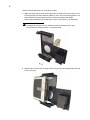
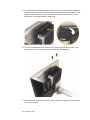
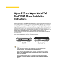
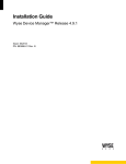
Wyse VX0L/LE Dual VESA Mount
Installation Instructions
The bracket enables a Wyse VX0L or VX0LE thin client to be mounted to a wall or on most
VESA compliant mounting surfaces and monitors. Both VESA 75 mm and 100 mm
mounting patterns are supported. The mounting bracket consists of two (2) pieces. The
larger bracket piece attaches to the mounting surface using the VESA mounting patterns.
User-provided hardware must be used that can withstand a force of 25 pounds (11.35
kilograms). The thin client is inserted in an upright position and cables are attached. The
smaller bracket piece attaches to the VESA compliant mounting monitor. The two bracket
pieces are then joined with four (4) thumb screws.
Notes
When determining location, take into account the cable lengths of the
monitor, keyboard, mouse, power supply, and peripherals.
Mount the thin client only as indicated; improper orientation (where the back
panel or front panel is facing down) could inhibit the dissipation of heat from
the device and damage it.
Do not enclosed the thin client in a confined environment without proper
ventilation. If you have questions, contact the Wyse Sustaining Engineering
Group.
2
Use the following instructions to mount the thin client:
1. Attach the larger bracket to the mounting surface (a swing arm mount is shown). The
mounting surface can have either the VESA 75 mm or 100 mm mounting pattern. The
bracket should be placed upright as shown. Secure the bracket with proper
user-provided hardware that can withstand a force of 25 pounds (11.35 kilograms).
Note
If installing on a hollow wall, any standard anchoring method may be used,
such as screws, butterfly anchors, or expansion bolts.
2. Slide the thin client into the mounted bracket using the pre-assembled guide rails until
it clicks into place.
3
3. Place the power adapter in the side pocket.
Note
If you have mounted the bracket to a wall, now is most convenient time to
attach all desired connections to the thin client.
4. Position the smaller bracket on the monitor as shown to match a set of mounting holes.
Both VESA 75 mm and 100 mm mounting patterns are supported. The bracket should
be placed with the turned edge on top (pointing downward). Secure with four (4)
user-provided screws (do not overtighten).
Note
If you have mounted the thin client bracket to a wall, now is most convenient
time to attach all desired connections to the monitor before assembling the
two brackets pieces together.
5. To assemble the two brackets together, face the mounted monitor bracket towards the
mounted wall bracket. Lift the monitor bracket a little higher than the wall bracket, and
tipping it forward at the top, guide it downward so that the monitor bracket’s turned
edge hooks over the wall bracket’s raised edge.
6. Line up the screws holes of the bracket pieces (two on top and two on bottom) and
secured with four (4) four thumb screws provided (do not overtighten).
7. Make all desired connections, and then connect the power adapter’s AC power cable
to an electrical outlet.
9/09
883863-11 Rev. A