1
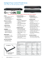
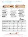
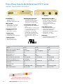
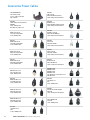
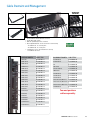
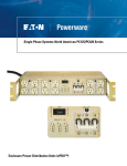
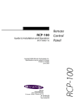
PowerChain Management solutions Eaton ePDU Industrial Products Catalog Table of Contents Single-Phase Systems-North American T982 Series..........................................................................................1 Intelligent Power Control IPC3600 Series..........................................................................................................4 Intelligent Power Control IPC3400 Series..........................................................................................................5 Intellgient Power Control IPC34XX-Net Series...................................................................................................6 Intelligent Power Control....................................................................................................................................7 Single-Phase Systems-North American TPC115-10 Series.................................................................................8 Single-Phase Systems-International TPC2365 Series.........................................................................................9 Three-Phase Systems-North American TPC4100 Series..................................................................................10 Three-Phase Systems-North American PC2641 Series....................................................................................11 Three-Phase Systems-North American PC975 Series......................................................................................12 Three-Phase Systems-International PC302-I/MTD...........................................................................................13 Three-Phase Systems-International PC2672 Series..........................................................................................14 Non-Rackmount Power Distribution Units UPS Extension Systems................................................................15 Sample Remote Circuits....................................................................................................................................16 Remote Control Panels......................................................................................................................................17 Accessories Power Cables................................................................................................................................18 Cable Restraint and Management.....................................................................................................................19 Environmental, Surge Suppression and EMI/RFI Filter Performance...............................................................20 Single-Phase Systems-North American T982 Series 120V~ OR 240V~, 15A, 20A and 30A, 50/60Hz T982C1 Front RACK MOUNTING • 19” X 1.72” (1U) x 7.0” • Width is 17.5” without mounting ears • 16-gauge steel, color black • Detachable mounting brackets allow for several mounting options POWER INPUT • Power cable with plug is attached to unit through the rear panel cable grip 12 NEMA OUTLETS • Straight blade or twist lock are optional • Optional cable restraint system with cable management. P/N: KIT-CABLRES-03 EMI/RFI FILTERING (Optional) • Filtering is both common mode (line - ground) and differential mode (line - line) • Refer to Chart 4 (15/20A), Chart 5 (30A) on page 20 T982C1 Rear SPIKE/SURGE SUPPRESSION • Transient voltage surge suppression prevents damage due to voltage fluctuations • Metal oxide varistors (MOVs) are utilized line to line (or neutral) • MOVs provide long life protection while withstanding large transients with little degradation URRENT MONITORING (Optional) C • Front panel display shows current draw of connected equipment • Two digit display shows current from 0-30 amps with ±1 amp accuracy • Monitor will help to prevent system overload and ease installation Optional Current Monitoring INDICATOR LIGHT • One blue LED indicator light per circuit breaker • Light illuminates when the circuit breaker is on and power is present at the input BRANCH CIRCUIT PROTECTION • Electromagnetic circuit breakers to prevent temperature from affecting the trip point • UL listed branch circuit breakers are provided where required by UL 60950-1 standards Optional cable restraint system (Refer to page 19) KIT-CABLRES-03 (Color Black) www.epdu.com 1.800.356.5794 1 T982 design your own part number guide Visit www.epdu.com for stock configurations. T982 Option 1 A1 = 120V/15A input, 15A outlets A2 = 120V/20A input, 20A outlets B1 = 240V/15A input, 15A outlets B2 = 240V/20A input, 20A outlets B3 = 240V/20A input, 15A outlets C1 = 120V/30A input, 15A outlets C2 = 120V/30A input, 20A outlets F1 = 240V/30A input, 15A outlets F2 = 240V/30A input, 20A outlets F3 = 240V/30A input, 15A outlets G1 = 120/240V/30A input, 5-15Rs H1 = 120/240V/30A input, 6-15Rs J1 = 120/240V/30A input, 5-15/6-15Rs Option 2 F = Filter N = No Filter - - Option 6 09 = 9-foot power cable 15 = 15-foot power cable Option 5 0 = No current meter 1 = Current meter Option 4 S = Straight blade Plug L = Locking Plug Option 3 S = Straight blade outlets L = Locking outlets Option 1: Voltage and Current Configuration See next page Option 2: EMI/RFI Filtering Choose “N” for no filtering or “F” for filtering. See Chart 4 (15A/20A units) Chart 5 (30A units) on page 20 filtering specifications. Option 3: Receptacle Type Choose either straight blade or twist lock style receptacles. See the table in Option 1 for a view of the available receptacles. Their NEMA designation number refers to the receptacles. Option 4: Plug Type Choose either straight blade or twist lock style plug. See the table in Option 1 for a view of the available plug styles. The NEMA designation number refers to the plug. Verify you have the correct type of mating receptacle available at your facility. Plug types limit the voltage and current options. Option 5: Current Meter This unit is available with or without a front panel digital current reference meter. This two-segment current reference meter will display the current value of the connected load. (The meter is an AC averaging meter.) This allows you to properly load your PDU to avoid an overload situation. This can also be used for monitoring to detect a fault before it occurs. The display shows two digits with no decimal place. The meter is accurate to ±1 amp resolution. The current meter option is not available on the following versions: G1 and J1. Option 6: Power Cable Length The power distribution unit has either SO, SOOW or SJT type power cable. The length can be specified as 9 feet or 15 feet. The maximum length allowed by UL standards for an attached power cable is 15 feet. For permanent installations exceeding 15 feet, a licensed electrician should install a permanent circuit. 2 eaton corporation ePDU Industrial Products Catalog T982 design your own part number guide G G Option 1: Voltage and Current Configuration Z G G W W W G G G G G W L21-30P Y Z G G T982 Series Version Voltage/Current Input/Output Y Y W 6-15P 5-15P Y 6-15R 5-15R Straight Blade A1 120V/15A 12A Output G W G Y 1-pole 15A Y G A2 120V/20A 16A Output X G Y 1-pole 20A G Y G G G W G W W 5-15P G B1 240V/15A 12A Output 2-pole 15A 5-15P B2 240V/20A 16A Output 2-pole 20A B3 240V/20A 16A Output 2-pole 20A C1 120V/30A 24A Output 2-pole 15A UL489 NA C2 120V/30A 24A Output 2-pole 20A UL489 NA F1 240V/30A 24A Output (2) 2-pole 15A UL489 NA F2 240V/30A 24A Output (2) 2-pole 20A UL489 F3 240V/30A 24A Output (2) 2-pole 15A UL489 NA G1 120/240V/30A 24A Output (2) 2-pole 15A UL489 NA H1 120/240V/30A 24A Output (2) 2-pole 15A UL489 NA J1 120/240V/30A 24A Output (2) 2-pole 15A UL489 NA G W X G G G G G 6-20P Z G Y Y WY G W G G GY G G W W 5-15P X Y G G W Y W 5-15P X Y Y W W Straight Blade G G W W X Y W G X G G Z G G G YY G W W X G 6-15R Y 5-20P G G W Y X G GW Y G 5-15R W G G W 5-20R Y G Y G W W Y X X G Y G W G G 5-20P W Z G W Z G Y X Z W G X G W Y W G Z G Y X G Y Y W Z WG X W 5-20R W 6-20R 6-20P L5-15R X 6-20R W L21-30P Y L5-20P W X Y 6-20PY 5-20R 6-20R L21-3 L21-30R 6-20R G G Twist6-20P Lock Z G Y Y L14-20R G G G L5-20P L21-30R W L5-30P Y W G G W X L21-30P 5-20R X Y W G W W W G W L14-20R Y XG Z W G X Y L21-30R G X Y X G G G G W G 6-20R G W 6-20P 6-15P W WG W 5-20R 6-15R L5-15P L5-20PWW G 5-20R Y L5-15R L21-30P G 5-15P 5-15R Z WL21-30P 5-20P W IEC-309 5-20P L15-30P L5-30R Y Y Y L5-20R L5-20R L6-20P X L6-30P L14-30P W Z Y Y Y L21-30P Y Y L21-30P X Y Y G 5-20R 5-15R G L14-20P IEC-309 L5-15P 5-20P G L5-20P L5-15R L5-20P L5-30P L5-30P G G G L14-20R Z Z Y G G L5-20R L5-30R L5-30R G W L6-30P G Y L5-20R L14-20R L14-30P L6-20P L21-30R L6-30P L15-30P L14-30P G L21-30R W G Y W X 6-20R 6-20R X W 6-15P W6-20P Z W W6-15R G X WZ X G 6-20P X X Y Y X Y Y 5-15P G GG WX L21-30 G 5-20R G G 5-15R Y L21-30R 6-15P 6-20R W Y W Z G GG Y W W W XG G G W X 5-20R W G G Output Connectors 6-15P5-15R 6-15R5-20P 5-15P W Y W Z G X W G G Y X G G W W 5-15P 5-15R W W Y L6-20P L6-30P L14-30P Y Y 5-20R 5-15R 5-20PL5-15P 5-15P L5-15R G IEC-309 G G L6-20P 6-15P 6-15R X W WG W X X G G G 5-20P G G W G W G L21-30P W 6-15P Y X Y 6-15RY Y G L14-20R G W W G W L14-20P L5-15R W L5-20P L5-30P L5-15P W L21-30R W Z G G IEC-309 W W WG W 6-20RG G 6-20P 6-20P 6-15P 6-15R Y W L21-30P L14-20P G Z L5-15R L5-15P 5-15R L5-15R5-20R L5-20P L5-30P 5-20P 5-20P G GL5-15P 5-15P 5-20R 5-15R X G X GG IEC-309 G G Z G IEC-309 GG G Y G W X W L5-15P W 6-15R 5-15P IEC-309 6-15P G 6-15R Twist Lock 6-15P G GG G G L21-30P Y G W G G Y L14-20R W L21-30R 5-20R Y W 5-20P Z WG W W G G Y Input Connectors 6-20R 6-20P 5-20P W Circuit Breakers G W G W 5-15R W W L21-30P G5-15R 5-20R 5-15P G W 5-15P WW X Z W X Y G X W G G Z G W Y G G W W G G Y XG 5-15P 5-20R 5-15R 5-20P The following chart shows the available input/output voltage and current configurations. 5-15P 5-15R Most options have a choice of straight blade or twist lock connectors. This selection is made in options 3 and 4.5-20P W G G G W G G W G Y 5-15R GZ Y X Y G G Z W W Y W Y W Z YG X W X Y GX G G X GW G WX GG Y G W W W Y Y X G 5-20P GW G G W * G Y G WG G G G W G G G X G X Y G XG G YY Y W Y G G G Y W GW Y W X W Y G W G Y W W G W X Y W X G X Z X G Z G X Z X X W G X Y X Y Y G X X GW X G X G Y YG G G G W YG G G W G W Y Y YW Y G G Y G G W W Y W Y G Z YY G Y G G Y X Y X Y X ZY X X G W ZG X X Z G X W Y G Z Z G W W G G G G X W X G YY G G Y G Y G X W Y G G W WG Y X Y WY W G W Z W G G G W W G Y W W G YX X Y W Y W X W ZW XW Z W G W G X WX WG W X Y Y X XG G G GX GG G G W G X Y WX G G G X X Y X G WY Y G G G G GY Y Z X W X GG Z Y X G YW Z W GZ W G W G X GW Y Y X Y W YX Y X X GG Y X X W Z W XG Y W W W WX Z W X G Y G Y XG Y X G Y Y Y G G G W Y X Y Y GG X W Y G G GY X YG G X Y G G X YG Z G WG G Y W G ZG G X W Z Y G G GZ G G G G Y WY W G X X YW Y G Z X W Z Y ZX W Y W Z G X G G YW GX ZG G Y Z Y X W X X X GG G Y YY G X G G X GY G Y G X WX X X W W Y Y X W G Z X G G Z G G WG W W G G W W W G W W W X Y G YG W X WY W G G G G G W G Y Y G Y W Y G WZ G Y YZ W Y GY Y Y X W Y ZW W X X X Y X G X G X G G W X Y Y G G Y G G W X X Y Y G Z X W X Y G Y Y Y G W Y G W Y Y Y G X G Z W Y Z W W G G X WX X G GX Y X Y Y Y X G Y G G GX Y W X G XY G Z GY YG G X W Z GG G GGX X X X Y Z X W WG Y X X X G Z Z X G X G G Y G Z X G G G GG Y G G Y W G W W W W GY W W GY Y W G W G Z Z W X Y Y W X Z Z X G Y Y Y G YG G X W GY Y G G Y W X Y Y W G Z X X Y G X X W G G G G G W W G W X Y W W W G W G W W G W W X G Y W G G Z G Z Y Y W G G G Y Y Y Y G W Y X Y Y X Z YX Y X Z G X G W Z Y G ZX Z X G Y G Y G X Y G X G G Y WG W WG GG X X X X Y Y G G Y X Y W G W G W W G X Y Y G G G Y G WX G YX G YW X Z G W X G W G X G YX G Z ZX GY ZZ W Y Y GG GX W Z XW W W Y W W Y Y X G X X X G Y X GG G Y G G W G G W G W W W G W G Z W W Y Y G Y Z Z YG YW X Y Y Y YG G Y G G G W Z YX X X Y G Y Z X G ZW X X Z G ZX X GX G G YX X G X XW W X G Y G W G W G W Y G W G G W G Y G X Y G Y X G YY G G X X GGG X G Z Y G Z X XW W G G Z W G X X Z X Y Y ZY G X Z GZ W G X YZ Y W Z GY GY YX XG Y Y Y G Z YY G X X W Y W G Y G G G G W X Y X YG X XG W Y Y W W W G G G X W Y WW G Z G X W W W G GW YG Y G X Y X G G G X G G X YX YW G G G X G G Z G G W WG X G G Z W Y Y Y Z G G W G G YW Y W G G W Z Z YX W WG X X GW W W Y X Y Y X Y X X Y G G W W WZ G G WW G Y GW Y G Y Y G Y WX Y YY G G XZ W YW Z X X Y G X Y Y Z G G G W Z G W G X G Z G G X X Y X X Z Z YX Y Z YY Z Y G W Z Z GY X X G GG W W X X WG G G Y W G G G XY G G XX W G XG Z X Z Y G Z W G Z WX W WG Z X Y WG G Y X Y Y Y Y G G Y G Y Z Y YX X G Y G G Y X Y W Y Y G X G G X Y W G G W XG W GG W GW W X YW X Z W Z X W G X WW W W Y X Y W Z GW G G Y Y G G X Y G G Y YG G Y W Y Y YW YG Y Z G G W G Y G G Z Y G Y X Y WX G G X YW G X Z G X G X G W X ZG X Z Z G X G G Y G W G G G Z W YG G YY X W X X X G G Y G X Y G Y Y G G G G Z GX X X Z Y G G Y G G Z G ZW G X Y XY Y Z W G G Y Z W Y WW W X W YG W Y Y XY G X Y Y W X W W G G W X W W Y W Z W W X X Y G G G Y Y W YX Y X Y G G X W G G Y G G G YGG X X X GW Z X G Y G G Y G W GW W YWW W Y G G G G G Z ZX G Y Y XW GW G Y W G X G Y Y X Y X Y X G G G Z Y YXG Z X Y X W Y YZ G X G Y G WG Y G YG X YG X Z X G YG Z G G G ZZ X WY G G Y X Z W Y W W G W G G Y Z YW Z X W G X G X G G G W X X W X ZG G Y Y XY W W G ZG X G Y X Z G YX G G W W Y G G W W G W W G G W W G W G G Y W G W G G W G X W G WY W YZ Y G Y W XW W Y Y G G X G Y X Y Y WX X Y X GW Y XX G G Y X Y X W G Y W Y G W W G W G G G W G X Y G G Y Z X Z G Y Y Y X W GG G W Z Y G G G X Y Y Y X Z Z XG X GX Z Y X Y X Y Z X G X W G Y Z X G G G G G W G WG G W G W GW G Z G Y W G G G X Z W G YZ Y G X Y X G Y Y G G G G WZ G X G G G X G X Y W W G G G W G W W G Y Y G G W Y X Y G Y Z Y X G X Y Y W G W G Y WY G X WX X X Y X W Z W W Y Z X G Z G G G W G X G G Y YG W X X Y Y G X G W G GW W G Y G X GY W X X WX G YG W WW W Y Y G Y G XG W G G WW G W W W G Z X Y Y GY G G Y X Z Y G G XY G W W ZZ X Y X X Z X Y Y W G Z Y W W W X W X G X Y G Y X G X G G G W G W G W G WY Y G Y Z Y Y Y X Y X Y W Z Z X X X X W X G G Z X G Y G G G G GG W G G X G Y YY G G G WW Y X Z Z G G W G W Z W Y X X Y ZYG X X Y X W G G YZ X Y GG G G G Z G Y X Y X X G XY Y G W W X G G Y Y X G G W X X X Y Y Y G W G G W G GW Y W W G G X Y X X Z Y X Z W X G W W Y Y G G G X Y ZX XY G G G Y GY X X G Z G G G Y Y Y G G W G G Y Z G W X Y X Y Z Y Z X GY Y Y Y W G Z W Y X Y G Y X YX G Y W X X X G W G X Y G Y G Y G Y W X Z Y G Y G Y Z YY G X Y Y Z G XY X GZ G X Z G YZ X X G W GG YG G GX X Y G G Y X X Z G WW Z X X XX Y Y X Y G W G X W Z Y G ZX G G G G G Y WG X X W Y G W G YY G G Z W G GW X XX X G Y Y WW W G W W Y G G G Y Y G G G X W Y W G W W W Z G Y Y W G X Z W G Z G Y Y ZX G G W X W G YY X Y G X X Z Y Z X Z Y Y W GY W Y X G G Y G X W G G W W Y W X X Z WX X X W G W G G X W W G Y G G X Y G G G X Y X Y Z G ZW Y Y G G W Z W Y Y W Z X X Y G G G G Y GG W Y Y X G W G Y X W X X G Y W X Y Z X G W XZ G X X G Y Y G XXX G X G X Y YX X Z G Y G G G Y G Y G Z G G W G G G W G W G Y X Y X Z Y Z X Y G G X WX YY G Z G Y X GY XW G Z G Y X YGX G Y G G G W Y Y Y W XY W ZG XZ Y Y YW G Y Y XY Y Y Y X G X W G G W G W G W Z Y X Y Y X X Y G W Y G G X X Z G X Y Y G W Z Y G XG Y W W W G G X X Z G Z G X Y Y G W Z Y Y WY G X G G W W X Y X Z X G W G W YY G X Y G WG G G X X Y X Z ZY X W W X X G G G G W Y W G Y Y G Y G X Y X Z Z X Y X G Y G Y X X Y X X Y G W G G X Y X X G Y X G X XX G Z XG G WG W G Y W G Y G G Z YW X Y G G Z X X Z Y G Y Y Z Y G Y XY X Y Y X X G XXZ W G G W W G G W G G Y G W X G X Z Z G Y Z Y W Y YY Z Y G Y L14-20R L21-30R 6-20R 6-20P 6-15P 6-15R L21-30P L21-30P 5-20R 5-15R 5-20P L14-20R L14-20R L5-20R L6-20P L6-30P L14-30P L14-20P L5-15P L5-15R L5-20P L5-30P L6-30R L21-30R L21-30R Y IEC-309 6-20R YL6-15R 6-20P 6-15P 6-15R 6-20P L14-20R 6-20R L15-20P 6-15P L6-15R L21-20P 6-15R L15-20P L6-15P L6-15P G L14-20R G G L15-30P L5-30R L5-30R L5-20R L6-20P L6-20P L21-30R L21-30R L5-20R L6-30P L6-30P L14-30P L14-30P L6-30R L6-30R 5-15P 5-20R 5-15R 5-20P 6-20R 6-20R 6-20PW 6-15P W 6-20P 6-15R 6-15P 6-15R W X L6-15R X L15-20P L21-20PL6-15R L6-15P L15-20P L21-2 G L6-15P G G Y G L14-20P L5-15P L5-15R L5-20P L5-30P W G L14-20P L5-15P L5-15R L5-20P L5-30P W W L21-30P L21-3 IEC-309 5-15P Y 5-20R 5-15R Z X IEC-3095-20P 5-15P 5-20R 5-15R 5-20P Y Y G Y L21-30P 5-15P 5-20R 5-15R 5-20P L14-20R G Y W L14-20P L5-15P L5-15R L5-20P L6-30R L14-20R L14-30R G L6-20RG L5-30P L14-30R L6-20R L21-30R L21-30R IEC-309 L15-30R L15-30R L15-20R L15-30P L5-30R L21-20R 6-20R 6-20R L5-20R 6-20P L6-20P6-15R 6-15P L6-30P 6-20P L14-30P 6-15R 6-15P L6-15R L15-20PL15-20R L6-15P X G G W G G L14-30R L14-20P L5-15P L5-15R L5-20P L5-30P L14-30R L6-20R L14-20P L5-15P L5-15R L5-20P L6-30R L6-30R L5-30P L6-20R Y W L15-30R IEC-309 L15-30R L15-20R IEC-309 L15-20R L21-20R W W L21-2 L6-15R L6-15R L15-20P L15-20P L21-30P L21-20P L21-2 G L6-15P L6-15P G 5-15P 5-20R 5-15R G 6-20R L14-20PL5-15R 5-20P L5-20P L5-15P L5-15R L5-20P Y L5-30P L5-15PL21-30P L5-30P 6-15P L14-20P 6-15R 6-20P IEC-309Y5-15P IEC-309 L15-30P 5-20R 5-15R L5-30R 5-20P L15-30P L5-30R L5-20R L6-20P L6-30P L14-30P L5-20R W X L6-20P G L6-30P L14-30P L14-20R Y YX L21-30R L21-30R Y Y G 6-20R 6-20R 6-20P 6-15P 6-20P 6-15R X GG G 6-15P L14-20R W Y L14-30R L6-20R 6-15RL15-30R Z L21-30R C13 L15-30P L5-30R L15-20R Y 6-20R X L5-20R L6-20P L6-30R L6-30P L14-30P 6-20P 6-15P 6-15R X X G W G G G G G L14-20P L5-15P L5-15R L5-20P L6-15R L14-30R L14-30R L5-30P L14-20P L15-20P L5-15P L5-15R L5-20P L21-20P L5-30P L6-20R L6-20R L6-15P Y IEC-309 Y Y L15-30R L15-30R IEC-309 L15-30P L21-2 L5-30R L15-20R L15-20R L15-30P L5-30R L21-20R L5-20R L6-20P L6-30P L14-30P L5-20R L6-20P L6-30P 5-15P L14-30P 5-15R L21-30P 5-20R W 5-20P G Y Y L14-20R L21-30R L15-30P L5-30R L5-20R L6-20P L5-20R 6-20R L6-20P 6-15P L5-30R L6-30P L14-30P L6-30P 6-15RL15-30P L14-30P L14-20R 6-20P W G L6-30R G W L6-30R L5-15P L5-15R L5-20P L21-30R X IEC-309 6-20R L6-15R L15-20P L21-20P X L6-15P L6-15R 6-20P L15-20P 6-15P X GW L21-20P 6-15RW G L6-15P G G G Y L21-30P Y Y L14-20P L5-15P L5-15R L5-20P L5-30P L5-15P L5-15R L5-20P L5-30P 5-20R 5-20P X L14-30R 5-15R IEC-309 IEC-309 L6-20R L6-30RL15-30R5-15P X G L21-20R G L5-15RY L6-15R L15-20PL15-20R L6-15P L21-20P G L14-20P L5-15P L5-20P L5-30P IEC-309 Y L6-30P X L5-30RL6-30P L15-30P L14-30P Y Z L5-30R X L5-20R L6-20P L6-20P L5-20R 5-20R L14-30P L21-30P L15-30P L6-30R G L6-30R 5-15P Y 5-15R W G 5-20P L6-15R L21-30R L15-20P L14-20R L6-15P L21-20P L6-15R X L15-20P L21-20P L6-15P X X 6-20R L14-30R G L6-30R L6-20RW GG L15-30R GW L6-30R L14-30R 6-20P L15-30R 6-15P 6-15R L21-30P L15-20R L6-20R5-15P 5-20R 5-15R L21-20R 5-20P L15-20R X Y L6-15R Y L15-20P L21-20P L6-15R L15-20P X X L21-20P Y L6-15P L6-20P X L6-15P L6-30P L14-30PL21-20R L5-20R L14-20P L5-15P L5-15R L5-20P X L5-30P G W G G IEC-309 G G L21-30P Y L14-20P L5-15PGX Y Y Z YL5-15R Y L5-20P L5-30P 5-15P 5-15R 5-20P X Y X L14-30R 5-20R IEC-309 X L6-20R L15-30P L5-30R X L15-30R L5-20R L6-20P G W L5-20R L14-20R L5-30R Y L6-20P L15-20RL6-30P L6-30P L14-30P W L14-30P L21-20R L21-30R Y G G G 5-15P 5-20R 5-15R 5-20P 6-20R 6-20P 6-15P 6-15R L15-30P Y Y L5-30R Z L6-20P L14-30P 5-15P L5-20R 5-20RL15-30R L21-30PL14-30R 5-15R 5-20P L14-30R L6-20R L6-30R L6-30P L6-30R L6-20R L15-30R L15-20R L14-20R L21-20R L6-15R X L15-20P L21-20PL15-20R L6-15R L15-20P L21-20RL6-15P L21-30R L21-20P L6-15P X X X 6-20R G W G L14-30R L14-30R 6-20P L6-20R 6-15P L6-20R 6-15R G L15-20R G L15-30R L15-30RL21-20R5-15R L15-20R L21-30P G X Y 5-15P 5-20R L21-20R Y 5-20P Y L14-20R X Y X X XW L5-15P L5-15R L5-20P L5-30P L6-30R L14-20P L21-30R G IEC-309 Y G L15-30P L5-30R Y Y G G 6-20R L5-20R L6-20P G L6-30P L14-30P 6-20P 6-15P L6-15R 6-15R L15-20P L6-15P X Y Y Y Z X L14-20R Z L15-30P L5-30R L5-20R L6-20P L6-30R L6-30P L14-30P G W Y L21-30R L6-30R 6-20R 6-15R L21-20P 6-20P Y L6-15R L15-20P 6-15P5-15R L6-15R L15-20P L21-2 L6-15P L6-15P L21-30P L14-30R L14-30R 5-15P 5-20R L6-20R L6-30R 5-20P L6-20R L15-30R L14-20R L15-30R L15-20R L14-20P L5-15P L5-15R 6-20R L21-30 L5-30P L21-20R L21-20R L5-20P 6-20P 5-20R 6-15P5-15R 6-15R IEC-309 L15-20R L21-30R L6-15R 5-15P L15-20P L21-20P 5-20P L6-15P X X X 6-20R 6-20P X 6-15P 6-15R W G ZX X G W GYG G G GY YY X X YG Y 5-15R Y G Y L6-30R G G W W X G Y Z Y G 5-20R 5-15P 5-20P Y * NA G G W Y Y G G X X NA G NA NA W L14-20R L14-20P L5-15P L5-15R L5-20P L5-30P L14-30R L6-20R IEC-309 L15-30R L21-30R L15-20R L15-30P L5-30R L5-20R L6-20P6-15P L14-30P6-20P 6-20R L6-30R L6-30P6-15R Y Y Z W L6-15R L15-20P L21-20P L14-30R L14-20P 5-20R L5-15P L14-30R L6-15P L5-15R L5-20P L5-30P L6-20R L6-30R L6-20R 5-15P 5-15R 5-20P IEC-309 L15-30R L15-30R L15-20R L15-20R L21-20R L21-2 Y L15-20P L6-15R L21-20P L6-15P L21-30P L14-30R 5-15P 5-20R 5-15R L6-20R 5-20P L15-30R L14-20P L5-15P L5-15R L5-20P L5-30P L14-20R L15-20R IEC-309 L21-20R L21-30R L15-30P L5-30R X X L5-20R L6-20P L6-30P L14-30P 6-20R X 6-20P 6-15P 6-15R W L5-15P L21-30R L5-15R L5-20P Y G G IEC-309 G 6-20R 6-20P L5-15P L5-15R L5-20P L5-30P 6-15P L14-20P 6-15R Y Y Z IEC-309 C13 L15-30P L5-30R L5-20R L6-20P L6-30R L6-30P L14-30P L14-30R L6-20R L15-30R L15-20R L21-20R L14-30R L6-15R L15-20P L6-20R L6-15P L5-15P L5-15R L5-20P L5-30PL21-20P L14-20P L15-30R L15-20R IEC-309 L15-30P L5-30R L21-20R L6-20P Y L5-20R L6-30P L14-30P X 6-20R L21-3 L14-20R6-15P G 6-20P L15-30P 6-15R5-20P L5-30R L21-30R 5-15P 5-20R 5-15R L5-20R L6-20P L6-30P 6-20P L14-30P 6-20RL6-30R Y 6-15P 6-15R L21-30P 5-15P 5-20R 5-15R 5-20P L6-15R L14-20P L6-20PL15-20P L6-30P L6-15P L14-30P L21-20P L5-20R L5-15P L5-15R L5-20P L5-30P IEC-309 L15-30P L5-30R L5-20R L6-20P L6-30P L14-30P L21-30P L5-15P L5-15R L5-20P L5-30P 5-20R 5-15R 5-20P L14-30R5-15P L6-20R L6-30R IEC-309 L15-30R L21-20R L6-15R L15-20PL15-20R L6-15P L21-20P L15-30P L5-30R L5-20R L6-20P L6-30P L14-30PL6-30R X G L6-15R L15-20P L21-20P L6-15P Y L6-30R L14-30R L6-20R L5-15R L5-20P L15-30R L21-30R IEC-309 L15-20RL5-15P L21-20RL14-20R L6-15R L15-20P L21-20P L6-15P6-15P L14-20P 6-20P L21-30R6-20R 6-15R L5-15P L5-15R L5-20P L5-30P L6-30R IEC-309 L15-30P L5-30R 6-20R L5-20R L6-20P 6-20P 6-15P L6-30P L14-30P 6-15R L6-15R L6-30R L6-20R L15-20P L14-20R L5-30R L14-30R L6-15P L15-30R L5-20R L6-30P L21-20R L14-30P L6-15R L15-20P L21-20P L21-30R L6-15P L15-20RL6-20P 6-20R 6-20P 6-15P 6-15R L14-30R L6-20R L6-30R L15-30R X X L15-20R L21-20R G L6-15R L15-20P G L21-20P L6-15P Y L14-30R L6-20R Y L21-30P L15-30R L15-20R 5-15P 5-20R 5-15R 5-20P L21-20R L5-20R L6-20P L6-30P L14-30P L14-30R L6-20R L15-30P L5-15PL15-30R L5-15R L5-30R L15-20R L5-30P L5-20R L6-20P L6-30R L6-30P L14-30P L21-30P L14-30R L5-20P L6-20R 5-20R 5-15R 5-20P IEC-309 L15-30R L15-20R 5-15P L21-20R L14-20P L5-15P L6-15R L5-15R L5-20P L15-20P L5-30P L6-30R L21-20P L6-15P IEC-309 L6-15R L15-20P L21-2 L6-15P L14-30R L6-20R L14-20P L5-15RL21-20R L5-20P L5-30P L15-30R X IEC-309 L15-20RL5-15P G X X Y G Y Y Z Y G Y W NA *20A twist lock outlets are not available to fit a standard duplex opening, so 15A outlets are used in these versions. G Y L6-20R G X L6-30RL15-30R L6-15R L14-30R L6-20P Y L6-30P L14-30R L6-20P L6-20R L6-20R L6-30P L15-30R L15-30R L14-30P L14-30R L6-20P L6-20R L6-30P L15-30R L14-30P L14-30R G X X Z X G Y www.epdu.com 1.800.356.5794 G Y G Y L6-30R Y X L6-15R X Z G L15-20P L21-2 L21-20P L6-15P Y G L15-20R L14-20P L5-20P L5-30P L15-20P L6-15P L5-20PL6-15P L5-30P L21-20PL14-20P L14-30R L5-20R L15-20R L5-20R L15-20R X Y L14-30R L15-30R L21-20R • TheL15-30R T982F3 is picturedL15-20R at the left L5-15P L6-30R L5-15R IEC-309 L6-15R L6-30R • This version features IEC C13 computer style outlets L5-15P L5-15R L6-15R L15-20P IEC-309 L6-30R • The power input is 30A L6-15R L15-20P L15-30P L5-30R L5-20R L14-30P L6-20R L6-20R L14-20R L21-30R L15-20P L6-15P L5-20R L14-20R L5-30R L21-30R L15-20R L15-30P L21-2 L5-30R L6-30R 6-20R 6-20P L6-15R 6-15R L21-20R L6-20P L6-30P L14-30P L14-30R L21-20P L15-30R L6-20R 6-20R 6-20P L5-20R 6-15R L6-30P L14-30P 6-15P L15-20R L15-20P L6-15P L6-20P 6-15P L15-30P L21-2 L15-20R L5-30R L21-20R L15-30P L5-30RW L21-20R W Y X G Y X G L6-15P X X G W Y G L21-20P Y Z Z 3 Intelligent Power Control IPC3600 Series 120V~ or 240V~,15A, 20A, 30A, Single Phase, 50/60 Hz IPC3601 Rear IPC36XX- Front CB IPC3602 Rear Please refer to page 18 for power cable assemblies to match your country specific requirements. OVERLOAD PROTECTION • Push button circuit breaker pops out when an overload occurs • Push to reset CHASSIS • 1.72” (1U) x Depth 9.5” x Width 19.0” • Weighs approximately 12 lb. • Powder coated black steel • Detachable mounting brackets allow for several mounting options SERIAL/ETHERNET • Serial RS232 via RJ22 connector on the rear. 6’ RJ22 to DB9 cable included • Serial baud rate is 9600 default or 38,400 maximum • Ethernet (10/100) network via RJ45 connector on the rear. 6’ network cable included • Network setup allows DHCP or any static public/private IP address NEMA or IEC 320 OUTLETS • IPC3601 has 8 IEC 60320 type C13 (computer style) outlets • IPC3602 has 8 NEMA 5-15R (3 prong) outlets 12 INDICATOR LIGHTS • Main power system on • Power “on” to outlets 1-8 • 2 Data and ethernet link POWER INPUT • IEC 60320 Type C20 Inlet • Mating power cables must be ordered separately (page 18) • IPC3601 has a full range power supply for use at 100-240V EMI/RFI FILTERING • Common Mode - line to ground • Differential Mode - line to line • Filtered inlet isolates noise before entering the system • Refer to chart 4 on page 20 PIKE/SURGE SUPPRESSION S • Line to Neutral (or Line) • Refer to chart 1 on page 20 KIT-CABLRES-01 Optional Cable Restraint System (refer to page 19) 4 SOFTWARE INTERFACES • Web interface provides a graphic control interface through a Web browser (IE, Netscape, Mozilla) • Telnet interface provides a text menu control interface with any terminal emulation software • SNMP allows read/write capability with trapping • E-mail notification system provides e-mail alerts or logs showing user activity • Serial interface provides a text menu control interface with any terminal emulation software • FTP utility allows firmware upgrades SOFTWARE SECURITY • User name/password security • Settings allow the administrator to disable unused interfaces SOFTWARE FEATURES • Administrator and multiple users can be configured • User level access can be limited to specific outlets • Unit and outlet names can be configured • Outlet groups can be created to perform an action on multiple outlets • Outlet control includes individual, group and all outlet global control • Outlet actions include on or off and reboot • Global sequence allows all the outlets to be turned on or off in a preset sequence up to 999 seconds • Outlet reboot automatically turns an outlet off and back on with one command at a preset time up to 999 seconds • E-mail notification allows up to two e-mail addresses to receive notifications of alerts or events AUTO-EVENT SCHEDULING • Administrator can configure on or off events for outlets or groups. The event occurs at the preset time daily or weekly. SPECIFICATIONS IPC3601 IPC3602 IPC3601-F3-3316 Approvals CB, CE, UL/cUL Listed, FCC UL/cUL Listed, FCC NA Voltage Input/Output (50/60Hz) 100-240V~ 120V~ 200-240V~ Current Rating 16A 16A 24A Full Load VA 1920 VA @ 120V~ 3840 VA @ 240V~ 1920 VA 5760 VA Ethernet/Serial YES YES YES Outlets IEC C13 NEMA 5-15R IEC C13 Circuit Breaker 20A 20A (2) 15/15A EMI/RFI Filter 20A 20A NO Surge Suppression YES YES YES Power Input C20 Inlet C20 Inlet Attached Power Cable/Plug Not Included Not Included 10’ - L6-30P eaton corporation ePDU Industrial Products Catalog Intelligent Power Control IPC3400 Series 120V~ or 240V~,15A, Single Phase, 50/60 Hz TABLE TOP • Height 3.4” x Depth 7.5” x Width 5.75” • Approximate shipping weight is 6 lb. OUTLETS • IPC3400-A1 has 4 NEMA outlets • IPC3400-AB has 4 IEC outlets (6) INDICATOR LIGHTS • (1) Main power • (1) Data light • (4) Power on to outlets 1-4 COMMUNICATIONS • RS232, Serial: 9600 baud only • Optional ethernet control via RJ45 connector (add -NET to part number) • Data terminal emulation software is required to communicate with the IPC internal command codes such a Telnet or Hyperterminal MODEM ACCESS • External modem must be put in auto-answer mode prior to making contact with the IPC EMI/RFI FILTERING • Common Mode - line to ground • Differential Mode - line to line • Refer to chart 2 on page 20 SPIKE/SURGE SUPPRESSION • L-N, L-G, N-G • Refer to chart 1 on page 20 POWER INPUT • IEC C14 power inlet • Power cable included: -AB version has 8’ C13 to C14 -A1 version has 9’ C13 to 5-15P ADDRESSING • The IPC comes with a default address but you can also create your own with any four alphanumeric characters OUTLET STATUS • Query the IPC for Outlet and Watchdog status, i.e. outlets are “on” or “off” MULTIPLE TIME DELAYTM (MTDTM) • Turn outlets “on” or “off” at one time • Sequence power up and power down to outlets 1 - 4 with a four second time delay (factory set) • Set power “on” sequence to any combination of outlets • Set the MTDTM timing from 1 second to 999 seconds, i.e. 009 = 9 seconds PASSWORD PROTECTION • For added security, a password feature is included which allows the user to assign a three alphanumeric character password WATCH-DOG/AUTO-REBOOT • The IPC will monitor the control connection and automatically reboot itself if the connection locks up. The auto-reboot is activated by the time-out period running down to zero. When this occurs the IPC will shut down all outlets for four seconds and restart in the default or user defined sequence • Set the Time Out Period to any number 0-9 where each digit represents 30 seconds, i.e. 3 = 120 seconds (user defined) COMMANDS AVAILABLE • All outlets on/off • Individual outlet on/off • Set up and Sequence on/off all outlets • Create password and unit address • Name outlets with 8 character name • Set up, enable or disable Watchdog • Display outlet and Watchdog Timer status SPECIFICATIONS IPC3400-A1 IPC3400-A1-NET IPC3400-AB IPC3400-AB-NET Approvals NA NA NA NA Voltage Input/Output (50/60Hz) 120V~ 120V~ 100-240V~ 100-240V~ Current Input 15A 15A 15A 15A Current Output 12A 12A 12A 12A Full Load VA 1440 VA 1440 VA 1440 VA/2880 VA 1440 VA/2880 VA NEMA Outlets (rear panel) 5-15R 5-15R IEC 60320 Type C13 IEC 60320 Type C13 EMI/RFI Filter 15A 15A 15A 15A Surge Suppression 270V 270V 270V 270V Power Cord/Length (rear panel) 14/3, 9’ 14/3, 9’ 14/3, 8’ 14/3, 8’ Power Input Plug 5-15P 5-15P IEC 60320 Type C14 IEC 60320 Type C14 Serial Control (RS232) YES YES YES YES Ethernet Control NO YES NO YES www.epdu.com 1.800.356.5794 5 Intellgient Power Control IPC34XX-Net Series 100V-240V~, 15A, 20A and 30A, Single Phase, 50/60 Hz IPC3402-NET Rear Panel IPC3401-NET Rear IPC3401-NET Rear Panel Front • Remote access via WAN/LAN, TCP/IP, Modem, or Direct RS-232: IPC3402-NET Rear IPC3402-2756 Rear Prevent costly site visits with remote-reboot and power management. • Sequence power up and down with Eaton’s patented Multiple Time DelayTM circuitry: Prevent inrush current problems such as system lock-ups and automatically control the order in which equipment within your network powers up or down. • Strap up to 10 IPC34XX systems together for control of 80 outlets: Use one IPC34XX-NET unit as the main system and strap (nine) less expensive IPC34XX (non-NET) units together to save money and increase overall control of your network equipment. • 100-240VAC / 15A or 20A input (IPC3401 or IPC3401-NET): Ethernet Strapping Switch One unit to purchase, stock and utilize worldwide. • Remote access disable and Local on/off control: When you need to work locally with the IPC34XX systems, the push of a button will prevent anyone from coming in remotely and the individual outlet on/off switches are also located on the front panel. • Cross platform compatible with Telnet and Browser Control: You can easily access and control the IPC34XX with either PC, Mac, Linux or Unix platforms running Telnet or via your Web browser. RS485 Strapping Connectors RS232 Serial (DB9 Connector) Rear Equipment Modem Network Modem Equipment 6 eaton corporation ePDU Industrial Products Catalog Up To 10 IPC Units Can Be Stacked Together Intelligent Power Control Please refer to page 18 for power cable assemblies to match your country specific requirements. SPECIFICATIONS: IPC3401 Approvals UL/cUL, CE, GS, FCC Voltage (50/60Hz) 100-240V~ Current Input 20A @ 120V~ 16A @ 240V~ IPC3401-NET IPC3402 IPC3402-NET IPC3402-A2 IPC3402-A2-NET IPC3402-2756 IPC3402-2930 UL/cUL, FCC UL/cUL, FCC UL/cUL, FCC UL/cUL, FCC UL/cUL UL/cUL 100-240V~ 120V~ 120V~ 120V~ 120V~ 120V~ 120V~ 20A @ 120V~ 16A @ 240V~ 20A 20A 20A 20A 30A 30A Current Output 16A 16A 16A 16A 16A 16A 24A 24A Full Load VA 1920 VA @ 120V~ 3840 VA @ 240V~ 1920 VA @ 120V~ 3840 VA @ 240V~ 1920 VA 1920 VA 1920 VA 1920 VA 2880 VA 2880 VA Outlets (IEC or NEMA) Type C13 Type C13 5-15R 5-15R 5-20R 5-20R (4) 5-20R, (4) 5-15R (8) 5-15R Circuit Breaker 20/20A 20/20A 20A 20A 20A 20A 20/10A 20/10A EMI/RFI Filter 20A 20A 20A 20A 20A 20A N/A N/A Surge Suppression 270V 270V 270V 270V 270V 270V 270V 270V Power Input Type C20 Inlet Type C20 Inlet Type C20 Inlet Type C20 Inlet Type C20 Inlet Type C20 Inlet L5-30P L5-30P 10/3AWG 10’ 10/3AWG 10’ Power Cord Power cables must be ordered separately. Refer to page 18 for power cable options. Ethernet Control NO Yes NO Yes NO Yes Yes Yes Serial Control (RS232) Yes Yes Yes Yes Yes Yes Yes Yes CHASSIS • 19” x 1.72” (1U) x 9.5” • Weight approximately 12 lb. • Detachable mounting brackets allow for several mounting options NEMA or IEC 320 OUTLETS • IPC3401 has 8 IEC 60320 Type C13 – Rated by UL/CSA 125V~/15A – Rated by UL/CSA/VDE 250V~/10A • IPC3402 has 8 NEMA 5-15R • IPC3402-A2 has 8 NEMA 5-20R • IPC3402-2756 has 4 NEMA 5-20R and 4 NEMA 5-15R • IPC3402-2930 has 8 NEMA 5-15R (11) INDICATOR LIGHTS • Main power to system-CB “on” • Individual power “on” to outlets 1-8 • Data acquisition and remote disable BAUD RATE • Default: 9600 baud EMI/RFI FILTERING • Common Mode - Line to Ground • Differential Mode - Line to Line • Filtered inlet isolates noise before entering the system • Refer to chart 3 on page 20 • IPC3402-2756 and IPC3402-2930 do not have filtering SPIKE/SURGE SUPPRESSION (TVSS) • Line to Line • Refer to chart 1 on page 20 • Multi-stage, both MOVs and SAPs BRANCH CIRCUIT PROTECTION • UL498 Listed Main Disconnect Breaker and guard, with a long time delay curve provides manual on/off switching and trips in an overload condition REMOTE or LOCAL CONTROL • Serial RS232 port (DB9 Male) for direct computer or modem connection • RS485 input/output for strapping up to 10 systems together over CAT.5 cable • Local: one on/off switch for each outlet • -NET SYSTEMS ONLY: RJ45 for network connections (Ethernet) POWER INPUT • IEC 60320 Type C20 EMI/RFI Filtered Inlet • Mating power cables must be ordered separately (page 18) • IPC3402-2756: attached 10’ cable and NEMA L5-30P REMOTE DISABLE • With the push of a button, disable remote access to the IPC when needed OUTLET STATUS • Query the IPC for Outlet and Watch Dog status, i.e. outlets are “on” or “off” POWER SUPPLY • The IPC3401 series features a full range power supply for operation at 100-240 Vac input/output STRAPPING • Strapping allows up to 10 IPCs (80 outlets) to be controlled at one address • Units are connected together via the RS485 “IN” and “OUT” connectors UNIT NAME / PASSWORD • The IPC comes with a default name @@@@, which can be changed to any four alphanumeric characters • Optional 3 character password MULTIPLE TIME DELAY (MTD) • Sequence power up and power down to outlets with a one second time delay (factory set) • User Programmable: – Set power “on” sequence to any combination of outlets – Set the MTD timing from 1 second to 999 seconds, i.e. 009 = 9 seconds AUTO-EVENT COMMAND RESPONSE • The IPC will automatically update the status of outlets (“on” or “off”) via serial or telnet SOFTWARE CONTROLS • Multi-platform compatible • Control via Terminal Emulation Software • Web interface for browser control COMMANDS AVAILABLE • All outlets on/off • Specific outlets on/off • Set up and sequence on/off all outlets • Create password and unit address • Outlet naming (8 characters) • Set up, enable or disable Watchdog • Display outlet and Watchdog Timer status • Automatically receive update outlet status whenever there’s a change • Auto-reboot outlet 1 with a five-second delay on restart www.epdu.com 1.800.356.5794 7 Single-Phase Systems-North American TPC115-10 Series 120V~ OR 240V~, 15A, 20A and 30A, 50/60 Hz TPC115-10-D Front RACK MOUNTED • 19” x 1.72” (1U) x 8.0” • Approximate shipping weight: 14 lb. (10) NEMA OUTLETS • 2 unswitched on front and 8 switched on rear panel. Unswitched outlets are tied to the SW-II outlet section POWER INPUT • Power cable with plug is attached to unit through the rear panel cable grip (3) INDICATOR LIGHTS • Main breaker power “on” and power to the unswitched outlets • Power “on” to the SW-I outlets • Power “on” to the SW-II outlets SPIKE/SURGE SUPPRESSION • L-N, L-G, N-G • Refer to Chart 1 on page 20 TPC115-10-D Rear MULTIPLE TIME DELAY™ (MTD™) • Activated “locally” or “remotely”, SW-I outlets power up immediately, followed four seconds later by SW-II outlets which is followed four seconds later by the sequenced remote I/O port. • Add “/MTD” after part number, i.e. TPC115-10-A/MTD EMI/RFI FILTERING • Common mode line to ground • Differential mode line to line • Refer to Chart 4 (15A/20A units) and Chart 5 (30A units) on page 20 OVERLOAD CIRCUIT PROTECTION • Electromagnetic breaker provides manual on/off switching and trips in an overload condition LOCAL/OFF/REMOTE SWITCHING • Local: Power “on or off” to the switched outlets • Off: When breaker is “on” but this switch is in the “off” mode, you will have power to the unswitched outlets only • Remote: Power “on or off” to the switched outlets via a remote device • Latching remote, on “LT” systems, has the selection switch wired for Remote/Off/Remote - There is no local control REMOTE I/O PORTS • 3 front/2 rear (see page 16) • Remote on/off and EPO control, EPO overrides remote and local control • Sequence Power Up additional equipment down line (3rd connector on front panel) • Latching remote feature - (N/C) EPO, momentary start – Add “-LT” to the part number when the MTD feature is not being used – Add “/LT” to the part number when the MTD feature is used SPECIFICATIONS TPC115-10-A TPC115-10-A2 TPC115-10-B TPC115-10-C TPC115-10-D TPC115-10-F Approvals UL/cUL UL/cUL UL/cUL UL/cUL UL/cUL UL/cUL Voltage Input/Output (50/60 Hz) 120V~ 120V~ 240V~ 120V~ 120V~ 240V~ Current Input 15A 20A 15A 30A 30A 30A Current Output 12A 16A 12A 24A 24A 24A Full Load VA 1440 VA 1920 VA 2880 VA 2880 VA 2880 VA 5760 VA NEMA Outlets 5-15R 5-20R 6-15R 5-15R 5-20R 6-15R Circuit Breaker with Kick Guard 15A 20A 15/15A 15/15A 15/15A (2) 15/15A EMI/RFI Filter 20A 20A 20A 30A 30A 30A Multi-Stage Surge Suppression 270V/150V 270V/150V 320V/270V 270V/150V 270V/150V 320V/270V Power Cord/Length 14/3, 9’ 12/3, 9’ 14/3, 9’ 10/3, 15’ 10/3, 15’ 10/3, 15’ NEMA Power Input Plug 5-15P 5-20P N/A L5-30P L5-30P L6-30P Optional Accessories Available RCP100-GRY Remote Control Panel (refer to pages 16-17) 8 eaton corporation ePDU Industrial Products Catalog KIT-CABLRES-08 Optional Cable Restraint System (refer to page 19) Single-Phase Systems-International TPC2365 Series 110-125V/200-240V~,16A, Single Phase, 50/60 Hz REMOTE SELECTION SWITCH • Local: Power “on or off” to the switched outlets • Off: When breaker is “on” but this switch is in the “off” mode, you will not have power to the outlets • Remote: Power “on or off” to the switched outlets via a remote device • Latching remote on “LT” models only, the selection switch is wired for Remote/Off/Remote - There is no local control • Refer to page 16 for remote configurations RACK MOUNTED • 19” x 1U (1.72”) x 7” • Approximate shipping weight: 9 lb. • TPC2365-2980 and TPC2365-3732 are 9.5” deep EMI/RFI FILTER • Differential Mode - line to line • Common Mode - line to ground • Refer to Chart 4 on page 20 SPIKE/SURGE SUPPRESSION • Line to Line • Refer to Chart 1 on page 20 IEC 60320 C20 Power Inlet • Power inlet is on the rear panel • Rated by UL/CSA at 125 Vac/20A or 250 Vac/16A Rated by TUV at 250 Vac/16A REMOTE INTERFACE • Remote on/off and EPO control - EPO overrides remote and local control • Sequence Power Up additional equipment down line (standard on all units • Latching remote “LT” models only - normally closed EPO, momentary start IEC 60320 OUTLETS (12) • Three sections of (4) switched outlets on the rear panel. Each group of four outlets are: – Rated by UL/CSA up to 250 Vac/15A – Rated by VDE at 250 Vac/10A MULTIPLE TIME DELAY (MTD™) (Optional) • Activated “Locally” or “Remotely”, Section 1 powers up, followed 4 seconds later by Section 2 which is followed 4 seconds later Section 3 then 4 seconds later the sequenced remote activates the next system in line INDICATOR LIGHTS (5) • Power to Section 1, 2 and 3 • 115 Vac or 230 Vac input selected OVERLOAD CIRCUIT PROTECTION • Electromagnetic breaker provides manual on/off switching and trips in an overload condition AUTO-VOLTAGE SELECTION • The AVS system automatically senses the input voltage and adjusts the internal components to use that voltage for the output Specifications TPC2365 TPC2365/MTD TPC2365-LT TPC2365/LT TPC2365-2980 TPC2365-3732 Approvals cTUVus, CE cTUVus, CE cTUVus, CE cTUVus, CE NA NA Voltage Input/ Output, (50/60 Hz) 110-125V 200-240V 110-125V 200-240V 110-125V 200-240V 110-125V 200-240V 110-125V 200-240V 200-240V Current Input 20A 20A 20A 20A 30A 30A Current Output 16A 16A 16A 16A 24A 24A Full Load VA 1920 VA / 3840 VA 1920 VA / 3840 VA 1920 VA / 3840 VA 1920 VA / 3840 VA 2880 VA / 5760 VA 5760 VA Circuit Breaker 2 Pole 20A 2 Pole 20A 2 Pole 20A 2 Pole 20A (3) 2 Pole 10A (3) 2 Pole 10A Multiple Time Delay NO YES NO YES YES YES EMI/RFI Filter YES (20A) YES (20A) YES (20A) YES (20A) YES (30A) YES (30A) Surge Suppression 320V 320V 320V 320V 320V 320V Outlets IEC 60320 Type C13 IEC 60320 Type C13 IEC 60320 Type C13 IEC 60320 Type C13 IEC 60320 Type C13 IEC 60320 Type C13 Remote Control Standard Standard Latching Latching Latching Latching Power Cable Not Included Not Included Not Included Not Included 10/3, 15’ 10/3, 15’ Power Input C20 Inlet C20 Inlet C20 Inlet C20 Inlet Bare Wire L6-30P KIT-CABLRES-08 RCP100-GRY Optional Cable Restraint System (refer to page 19) Remote Control Panel (refer to pages 16-17) www.epdu.com 1.800.356.5794 9 Three-Phase Systems-North American TPC4100 Series 120/208V~ Three-Phase WYE, 20A and 30A, 50/60 Hz TPC4100-AB Rear BRANCH CIRCUIT PROTECTION • UL489 Listed electromagnetic breakers, with a long time delay curve, provide both manual on/off switching and open (trip) automatically with an overload condition CHASSIS • 19” x 1.72” (1U) x 9.5” • Approximate shipping weight: 19 lb. • Detachable mounting brackets allow for several mounting options EMI/RFI FILTERING • Common Mode - line to ground • Differential Mode - line to line • Refer to Chart 8 on page 20 (3) INDICATOR LIGHTS • Provided for each phase power “ON” via breaker SPIKE/SURGE SUPPRESSION • Line to line • Refer to Chart 1 on page 20 KIT-CABLRES-01 (12) NEMA OUTLETS • (4) Per phase PH-Y and PH-Z on the rear panel and PH-X has two on the rear and 2 on the front panels POWER INPUT • Power cable with locking plug is attached to the unit through the rear panel cable grip Optional Cable Restraint And Management System (refer to page 19) SPECIFICATIONS TPC4100-A2 TPC4100-B TPC4100-AB TPC4100-C TPC4100-D TPC3474 Approvals UL/cUL Listed UL/cUL Listed UL/cUL Listed UL/cUL Listed UL/cUL Listed NA AC Voltage Input (50/60 Hz) 120/208V WYE 120/208V WYE 120/208V WYE 120/208V WYE 120/208V WYE 120/208V WYE AC Voltage Output 120V~ 208V~ 120V~ and 208V~ 120V~ 120V~ 120V~ Current Input Per Phase 20A 30A 30A 30A 30A 30A Current Output Per Phase 16A 24A 24A 24A 24A 24A Full Load VA Per Phase 1920 VA 2880 VA 2880 VA 2880 VA 2880 VA 2880 VA NEMA Outlets (12) 5-20R (12) 6-15R (6) 5-15R, (6) 6-15R (12) 5-15R (12) 5-20R (6) 5-20R, (6) 6-20R Listed Circuit Breaker (3) 1 pole/20A (3) 2 pole/15A (3) 2 pole/15A (3) 2 pole/15A (3) 2 pole/20A (3) 2 pole/20A Remote NO NO NO NO NO YES - Latching EMI/RFI Filter 30A 30A 30A 30A 30A NO Surge Suppression 150V 270V 150V 150V 150V 150V Cable 12AWG/5wire, 9’ 10AWG/5wire, 9’ 10AWG/5wire, 9’ 10AWG/5wire, 9’ 10AWG/5wire, 9’ 10AWG/5wire, 9’ NEMA Power Input L21-20P L21-30P L21-30P L21-30P L21-30P L21-30P RCP100-BLK-LT TPC3474 The TPC3474 is compatible with the RCP100-BLK-LT. 10 eaton corporation ePDU Industrial Products Catalog Three-Phase Systems-North American PC2641 Series 120/208V~ Three-Phase WYE, 30A, 50/60 Hz PC2641-D Rear RACK MOUNTED • 19” x 3.4” (2U) x 14.5” (recessed) • Approximate weight: 29 lb. (14) NEMA OUTLETS • 2 unswitched outlets • 12 switched outlets, 4 per phase (4) INDICATOR LIGHTS • Main breaker power “on” to system and unswitched duplex • Power “on” to PH-X, -Y, -Z outlets LOCAL/OFF/REMOTE SWITCHING • Local: Power “on or off” to the switched outlets • Off: When breaker is “on” but this switch is in the “off” mode, you will have power to the unswitched outlets only • Remote: Power “on or off” to the switched outlets via a remote device • When using the Latching remote, the selection switch is wired for Remote/Off/Remote. There is no local control. MULTIPLE TIME DELAY (MTD) • PH-X powers up immediately, followed 4 seconds later by PH-Y, which is followed 4 seconds later PH-Z, then 4 seconds later the sequenced remote activates the next system in line • PC2641-D/MTD and PC2641-D/LT only models SPIKE/SURGE SUPPRESSION • 320V MOV L-N • Refer to Chart 1 on page 20 EMI/RFI FILTERING • Common Mode - line to ground • Differential Mode - line to line • Refer to Chart 9 on page 20 POWER INPUT • Power cable with plug is attached to unit through the front panel cable grip BRANCH CIRCUIT PROTECTION • UL498 Listed electromagnetic breakers, with a long time delay curve, provide both manual on/off switching and trips automatically in an overload condition 4 REMOTE I/O PORTS • Remote on/off and EPO control, EPO overrides remote and local control • Sequence power up additional equipment down line (standard on all units) • Latching remote - normally closed EPO, momentary start. Units with “LT” in part number, i.e. PC2641-D-LT or /LT SPECIFICATIONS PC2641-D PC2641-D-LT PC2641-D/MTD PC2641-D/LT Voltage Input Three Phase (50/60 Hz) 120/208V~ 120/208V~ 120/208V~ 120/208V~ Voltage Output Single Phase (50/60 Hz) 120V~ 120V~ 120V~ 120V~ Current Input Per Phase 30A 30A 30A 30A Current Output Per Phase 24A 24A 24A 24A Full Load VA Per Phase 2880 VA 2880 VA 2880 VA 2880 VA NEMA Outlets 5-20R 5-20R 5-20R 5-20R Main Circuit Breaker (on/off switch) 30/30/30A 30/30/30A 30/30/30A 30/30/30A Secondary Circuit Breakers Per Phase 20/20A 20/20A 20/20A 20/20A Unswitched Duplex Circuit Breaker 20A 20A 20A 20A EMI/RFI Filter 30A 30A 30A 30A Surge Suppression 320V 320V 320V 320V Power Cord/Length/Plug 10/5, 15’, L21-30P 10/5, 15’, L21-30P 10/5, 15’, L21-30P 10/5, 15’, L21-30P Remote Control Standard Remote Latching Remote Standard Remote Latching Remote Multiple Time Delay NO NO YES YES This system is designed to be controlled Locally or Remotely via a remote control panel (refer to pages 16-17). www.epdu.com 1.800.356.5794 11 Three-Phase Systems-North American PC975 Series 120/208V~ Three-Phase WYE, 30A, 50/60 Hz PC975 Rear RACK MOUNTED • 19” x 3.4” (2U) x 14.5” (including 2.5” recess) • Approximate shipping weight: 29 lb. EMI/RFI FILTERING • Common Mode - line to ground • Differential Mode - line to line • Refer to Chart 9 on page 20 SPIKE/SURGE SUPPRESSION • 270V MOV L-N • Refer to Chart 1 on page 20 (11) NEMA OUTLETS • (2) Unswitched outlets • (1) Duplex and (1) twist lock per phase (4) INDICATOR LIGHTS • Main breaker power “on” • Power “on” to PH-X, Y and Z OVERLOAD CIRCUIT PROTECTION • Electromagnetic breakers, with a long time delay curve, provide both manual on/off switching and trips automatically in an overload condition LOCAL/OFF/REMOTE SWITCHING • Local: Power “on or off” to the switched outlets • Off: When breaker is “on” but this switch is in the “off” mode, you will have power to the unswitched outlets only • Remote: Power “on or off” to the switched outlets via a remote device • When using the Latching remote option, the selection switch is wired for Remote/Off/Remote - There is no local control MULTIPLE TIME DELAY™ (MTD™) • Activated “Locally” or “Remotely”, PH-X powers up, followed 4 seconds later by PH-Y, which is followed 4 seconds later PH-Z, then 4 seconds later the sequenced remote activates the next system in line POWER INPUT • Power cable with plug is attached to unit through the front panel cable grip PC975, PC975-LT PC975-1969, PC975-1969/LT PC975-2109, PC975-2109-LT Approvals UL/cUL UL/cUL UL/cUL Voltage Input Three Phase (50/60 Hz) 120/208V 120/208V 120/208V Voltage Output (50/60 Hz) 120V~ and 208V~ 120V~ and 120/208V~ 120V~ Current Input Per Phase 30A 30A 30A Current Output Per Phase 24A 24A 24A Full Load VA Per Phase 2880 VA 2880 VA 2880 VA Main Circuit Breaker (on/off switch) 4-Pole 30/30/30/30 4-Pole 30/30/30/30 4-Pole 30/30/30/30 Secondary Circuit Breakers Per Phase (3) 2-Pole 20/20 N/A (3) 1-Pole 20 Unswitched Duplex Circuit Breaker 20A thermal reset 20A thermal reset 15A thermal reset EMI/RFI Filter 30A 30A 30A Surge Suppression 270V 270V 270V NEMA Outlets (8) 5-20R and (3) L6-20R (8) 5-20R and (3) L21-30R (8) 5-15R and (3) L5-30R Power Cord/Length/Plug 10/5, 15’, L21-30P 10/5, 15’, L21-30P 10/5, 15’, L21-30P eaton corporation ePDU Industrial Products Catalog (4 N/O) REMOTE I/O PORTS • Remote on/off and EPO control, EPO overrides remote and local control • Sequence power up additional equipment down line (standard on all units) • Latching remote - (N/C) EPO, momentary start. “LT” systems SPECIFICATIONS This system is designed to be controlled Locally or Remotely via a remote control panel (refer to pages 16-17). 12 Three-Phase Systems-International PC302-I/MTD 120/208V~ or 230/400V~ Three-Phase WYE, 20A, 50/60Hz RACK MOUNTED • 19” x 3.4” (2U) x 8.5” with recess mounting • Approximate shipping weight: 19 lb. EMI/RFI FILTER • Differential Mode • Common Mode • Refer to Chart 2 on page 20 SPIKE/SURGE SUPPRESSION • Line to line • Refer to Chart 1 on page 20 VOLTAGE SELECTION SWITCH • Select 120/208V~ or 230/400V~ input • 120/208V~ input with 120V~ output • 230/400V~ input with 230V~ output LOCAL/OFF/REMOTE SWITCHING • Local: “On/Off” to switched outlets • Off: When breaker is “on” but this switch is in the “off” mode, you will have power to the unswitched outlets only • Remote: “On/Off” to switched outlets via a remote control device • Latching remote, the selection switch is wired for Remote/Off/Remote - There is no local control on the PC302-I/LT (14) IEC 60320 TYPE C13 OUTLETS • 12 on the front panel switched and 2 on rear panel unswitched • Rated by UL/CSA up to 250V~/15A • Rated by VDE at 250V/10A each POWER INPUT • External terminal block for power input is on rear panel • High Voltage Cover with attached cable/plug is available, reference below part numbers REMOTE CONTROL • Remote on/off and EPO control, EPO overrides remote and local control • Sequence power up additional equipment down line • Latching remote - (N/C) EPO, momentary start on PC302-I/LT only MULTIPLE TIME DELAY (MTD) • Activated “Locally” or “Remotely”, PH-X powers up, followed 4 seconds later by PH-Y, which is followed 4 seconds later PH-Z, then 4 seconds later the sequenced remote activates the next system in line (6) INDICATOR LIGHTS • Main power “on” • Power to phase X, Y, and Z • 120/208V~ input selected • 230/400V~ input selected See pages 16-17 for optional control panels. SPECIFICATIONS PC302-I/MTD PC302-I/LT Approvals UL/cUL, TUV, CE UL/cUL, TUV, CE Voltage Input (Selectable) 120/208 Vac or 230/400 Vac 120/208 Vac or 230/400 Vac Voltage Output Single Phase 120 Vac or 230 Vac 120 Vac or 230 Vac Frequency 50/60 Hz 50/60 Hz Current Input Per Phase 20A or 16A 20A or 16A Current Output Per Phase 16A 16A Full load VA Per Phase 1920 VA or 3680 VA 1920 VA or 3680 VA Main Circuit Breaker 4-Pole 20A 4-Pole 20A IEC 60320 Outlets Type C13 Type C13 EMI/RFI Filter Per Phase 20A 20A Surge Suppression 270V 270V Power Input Terminal Block Terminal Block REQUIRED CABLE ASSEMBLY OPTIONS: CBL100: 20A with 12/5 cable 9’ long terminated with a NEMA L21-20P for use in North America at 120/208V~ CBL102: 20A with 5x2.5mm Harmonized cable 9’ long. A plug is not provided so that the end user can provide the country specific plug for use in Europe at 230/400V~ www.epdu.com 1.800.356.5794 13 Three-Phase Systems-International PC2672 Series 120/208V~ OR 230V/400V~, Three-Phase WYE, 30A, 50/60 Hz VOLTAGE SELECTABLE RACK MOUNTED • 19” x 5.25” (3U) x 16.5” with recess mounting • Approximate shipping weight: 41 lb. POWER INPUT • 5’ power cable with IEC 309 plug is attached to unit through the front panel cable grip • Unit ships with mating connector to IEC 60309 outlets on front panel (17) IEC OUTLETS (12) C13 Type: • 120/208V Input, the output is 120V • 230/400V input, the output is 230V (4) C19 Type: • 120/208V input, the output is 208V • 230/400V input, the output is 230V (1) IEC 309 3-Phase/30A: • 120/208V input, the output is 120/208V • 230/400V input, the output is 230/400V EMI/RFI FILTERING • Common Mode - line to ground • Differential Mode - line to line • Refer to Chart 9 on page 20 (3) INDICATOR LIGHTS • Power “on” to PH-X, -Y, -Z BRANCH CIRCUIT PROTECTION • UL489 Listed Main Disconnect breakers, with a long time delay curve, provide manual on/off switching and automatically trip with an overload condition (4) REMOTE I/O PORTS • 2 Front / 2 Rear: one on each side is sequence and the other is for remote on/off and EPO control. The PC2672 is controlled remotely only • Latching remote - (N/C) EPO between pins 2 & 3, momentary start between pins 1 & 3 SPECIFICATIONS PC2672 Voltage Selectable Input Three Phase (50/60 Hz) 120/208V~ or 230/400V~ Voltage Output Single Phase on C13s (50/60 Hz) 120V~ or 230V~ Voltage Output Single Phase on C19s (50/60 Hz) 208V~ or 230V~ Voltage Output Three Phase on IEC 309 (50/60 Hz) 120/208V~ or 230/400V~ Current Input Per Phase 30A Current Output Per Phase 24A Full Load VA Per Phase 2880 VA at 120/208V or 5520 VA at 230/400V Main Listed Breaker 30/30/30A Secondary Listed Breakers, (1) Each For The C19 Outlets (4) 16/16A Secondary Listed Breakers, (1) Each For A Pair of C13 Outlets (6) 10A IEC 60320 Type C13 Outlets (12) 15A/125V or 10A/250V IEC 60320 Type C19 Outlets (4) 20A/125V or 16A/250V IEC 309 Outlet (1) 3-phase/30A EMI/RFI Filter 30A Power Cord/Length/Plug 10/5, 5’, IEC 60309 3P+N+PE, 30A CABLE ASSEMBLY OPTIONS: CBL113: 10/5 cable 9’ long terminated with a NEMA L21-30P at one end and a mating IEC 60309 connector at the other end. For use in North America at 120/208V~ CBL114: 5x4.0 mm harmonized cable 9’ long with an IEC 60309 connector at both ends. For use in Europe at 230/400V~ 14 eaton corporation ePDU Industrial Products Catalog This system is designed to be controlled Locally or Remotely via a remote control panel (refer to pages 16-17). Non-Rackmount Power Distribution Units UPS Extension Systems LPC120P: 120V~/30A input and output, 6’ cable (10/3) terminated with a NEMA L5-30P. There are (8) NEMA 5-15R outlets with a 15A thermal reset breaker for each duplex. 7.75”W x 3”H x 10”L LPC208-1P: 240V~/30A input and output, 6’ cable (10/3) terminated with a NEMA L6-30P. There are (4) NEMA L6-30R outlets. 7.75”W x 3”H x 10”Lx 3”H x 10”L LPC208-2P: 240V/30A input and output, 6’ cable (10/3) terminated with a NEMA L6-30P. There are (3) NEMA L6-20R outlets, each with a 2-pole 20A breaker and kick guard and (1) L6-30R unswitched outlet. 7.75”W x 3”H x 10”L LPC1224-1P: 120/240V~/30A input with 120V output, 6’ cable (10/4) terminated with a NEMA L14-30P. There are (12) NEMA 5-15R outlets with 15A thermal reset breaker for each duplex. 7.75”W x 3”H x 10”L LPC2872-1: 100-240V~/20A input via C20 power inlet. On/Off switch with green power on light. (6) IEC 60320, C13 receptacles. 2.67”H x 11”L x 1.75”W SPECIFICATIONS LPC120P LPC208-1P LPC208-2P LPC1224-1P LPC2872-1 Voltage Input/Output (50-60 Hz) 120V 240V 240V 120/240V 100-240V Current Input 30A 30A 30A 30A Per Phase 20A Current Output 24A 24A 24A 24A Per Phase 15A @ 120V 10A @ 240V Full Load VA 2880 VA 5760 VA 5760 VA 2880 VA Per Phase 1800 VA, 2400 VA Circuit Breaker (4) 15A N/A (3) 2P/20A (6) 15A N/A EMI/RFI Filtering N/A N/A N/A N/A N/A Surge Suppression N/A N/A N/A N/A N/A NEMA Outlets (8) 5-15R (4) L6-30R (3) L6-20R, (1) L6-30R (12) 5-15R (6) C13 Power Cord/Length 10/3, 6’ 10/3, 6’ 10/3, 6’ 10/4, 6’ IEC C20 Inlet NEMA Input Plug L5-30P L6-30P L6-30P L14-30P NA www.epdu.com 1.800.356.5794 15 Sample Remote Circuits Standard Remote Control Interface REMOTE START REQUIRES (2) CONDITIONS: 1. The “on/off/remote” switch must be in the “remote” position. 2. A maintained closure between pins 1 & 3 will turn the unit on. REMOTE POWER OFF REQUIRES (1) CONDITION: 1. Opening the maintained connection between pins 1 & 3 will turn off the switched outlets. REMOTE EPO REQUIRES (1) CONDITION: 1. A maintained contact between pins 2 & 3 will turn off the switched outlets regardless of the position of the “on/off/remote” switch. SEQUENCED REMOTE: Connect pins 1, 2 & 3 of the sequence port to pins 1, 2 & 3 on any remote port of the slave unit. (Do not connect to another “sequence” port!) The sequence port of the master unit activates 4 seconds after the final set of outlets turn on. Additional units may be daisy chained in this fashion. CAUTION! THIS TYPE OF REMOTE IS NOT TO BE SUBSTITUTED FOR A SAFETY INTERLOCK! EPO is normally open, so removing the EPO connection will not shut down the power to the unit. Latching Remote “LT” Control Interface REMOTE START REQUIRES (2) CONDITIONS: 1. A maintained contact between pins 2 & 3. 2. A momentary contact between pins 1 & 3. REMOTE POWER OFF OR EPO REQUIRES (1) CONDITION: 1. Opening the maintained connection between pins 2 & 3. Additional EPO or stop buttons can be connected in series between pins 2 & 3. This will turn off the switched outlets regardless of the remote switch position. SEQUENCE REMOTE: Connect pins 1 & 2 of the “sequence” port to any remote port on another “-LT” unit. The sequence port activates 4 seconds after the final set of outlets turn on. (Do not connect to another “sequence” port!) NOTE: “LT” units are designed for remote operation only. Even when the “REMOTE/OFF/LOCAL” switch is set to “LOCAL”, the unit still requires a power request from the remote ports to turn the unit on. REMOTE OPERATION: Most Eaton® units have more than one remote connector. Unless labeled as “SEQUENCE” they are wired in parallel. Connection to only one remote connector is required. It is recommended that an Eaton control panel be ordered for use with your PDU. Connectors are provided for those who wish to wire their own switches or control panels. We recommend using 14 AWG wire and not exceeding 50 feet for any remote cable. Mating control panels can be seen on our web site at www.epdu.com. If additional remote connectors are needed: The female AMP connectors used in our Power Controllers are: three pin - Part Number 1-480304-0 and four pin Part Number 1-480425-0, and are used with AMP Socket Terminals, Part Number 60619-1. The mating male AMP connector is: three pin - Part Number 1-480305-0, and four pin - Part Number 1-480426-0 and are used with AMP male contacts Part Number 60620-1. 16 eaton corporation ePDU Industrial Products Catalog Remote Control Panels RCP100 Series RCP100-BLK-LT EMERGENCY POWER OFF (EPO) • RCP100-GRY: Locking (N/O) EPO button for PDUs with the standard 3-pin remote I/O port. Turn to reset • RCP100-GRY-LT: Locking (N/C) EPO button for PDUs with the latching (LT) option. Turn to reset. • Per European requirements, there is a yellow square behind the EPO button RCP100-GRY RACK MOUNTED • 19” x 1.73” x 2.0”, flush mounted, 18 GA. Steel • Painted FED-STD 595 #26559 light texture Gray • Optional: Painted FED-STD 595 #26038 Black • Remote cable is 15’ long • Approximate shipping weight is 5 lb. ON/OFF SWITCH • RCP100-GRY: 2 position “ON/OFF” switch • RCP100-GRY-LT: 3 position spring return dial switch for “OFF” (turns unit off and holds off), “ON” (puts unit in a standby mode), “START” is a momentary action and powers up the unit Latching (LT) control panels must be ordered with power distribution units that are latching, identified by LT at the end of the part number. MODEL REMOTE TYPE HEIGHT COLOR RECEPTACLES SWITCH/EPO RCP100-GRY Standard 1U (1.75”) Gray None 2 position/Normally Open RCP100-BLK Standard 1U (1.75”) Black None 2 position/Normally Open RCP100-GRY-LT Latching 1U (1.75”) Gray None 3 position/Normally Closed RCP100-BLK-LT Latching 1U (1.75”) Black None 3 position/Normally Closed www.epdu.com 1.800.356.5794 17 Accessories Power Cables SUB-HRDWARE-032 C19 retaining clamp secures cables to the PDU with cable ties. 010-9343: CEE7-7 to C19 250V, 16A EUROPE (Schuko) 2.5M, 1.5mm/3-wire Harmonized 010-0026: 2.5M, 1.5mm/3-wire Harmonized 010-0034: 8 foot, 12AWG/3-wire Bare Wire (Pig Tail) to C19 010-9344: BS546A to C19 250V, 15A BRITISH (Old standard) 2.5M, 1.5mm/3-wire Harmonized 010-9334: NEMA 5-15P to C19 125V, 15A Straight Blade 8-foot, 14AWG/3-wire 010-9345: AS/NZS 3112 to C19 250V, 15A AUSTRALIAN 2.5M, 1.5mm/3-wire Harmonized 010-9335: NEMA 5-20P to C19 125V, 20A Straight Blade 8-foot, 12AWG/3-wire 010-9346: SI32 to C19 250V, 16A ISRAELI 2.5M, 1.5mm/3-wire Harmonized 010-9336: NEMA 6-15P to C19 250V, 15A Straight Blade 8-foot, 14AWG/3-wire 010-9347: CEI23-16 to C19 250V, 16A ITALIAN 2.5M, 1.5mm/3-wire Harmonized 010-9337: NEMA 6-20P to C19 250V, 20A Straight Blade 8-foot, 12AWG/3-wire 010-9351: BS1363A to C19 250V, 13A BRITISH 2.5M, 1.5 mm/3-wire Harmonized 010-9338: NEMA L5-15P to C19 125V, 15A Twist-Lock 8-foot, 14AWG/3-wire 010-0025: 8-foot 010-0027: 6-foot 010-0028: 4-foot 010-0029: 2-foot C14 Harmonized, 1 mm/3-wire to C13 100-240V rated 010-9339: NEMA L5-20P to C19 125V, 20A Twist-Lock 8-foot, 12AWG/3-wire 010-9365: C14 Male to C19 15A 8-foot, 14AWG/3-wire 010-9340: NEMA L6-15P to C19 250V, 15A Twist-Lock 8-foot, 14AWG/3-wire 010-0031: IEC 320 C14 to CEE7 SCHUKO 250V, 10A 1-foot, 1.5mm/3-wire Harmonized 010-9341: NEMA L6-20P to C19 250V, 20A Twist-Lock 8-foot, 12AWG/3-wire 010-0032: C14 to NEMA 5-15R 125V, 15A 1-foot, 16AWG/3-wire 010-9342: C20 Male to C19 20A 8-foot, 12AWG/3-wire 18 eaton corporation ePDU Industrial Products Catalog Cable Restraint and Management TRANSVERSE MOUNTING KIT-CABLRES-01 KIT-CABLRES-08 • Prevent downtime and accidental disconnection • Secure cables/plugs to PDU • Cable ties provide highest level of retention • Black “adjustable bracket” versions allow front or rear mounting – KIT-CABLRES-01 - fits 9.5” deep units – KIT-CABLRES-03 - fits 7” deep units • “Fixed bracket” versions allow attachment to rear only – KIT-CABLRES-08 - Black Vertical Models Cable Tray Rackmount Models Cable Tray V42 Series KIT-CABLRES-21 IPC34XX Series KIT-CABLRES-01 V70A1 Series KIT-CABLRES-24 IPC36XX Series KIT-CABLRES-01 V70A2 Series KIT-CABLRES-24 T17 KIT-CABLRES-03 V70AB Series KIT-CABLRES-22 T982 Series KIT-CABLRES-03 V70Bx Series KIT-CABLRES-24 TPC115-10 Series KIT-CABLRES-08 V70Cx Series KIT-CABLRES-24 T9092 Series KIT-CABLRES-08 V70F1 Series KIT-CABLRES-24 TPC2104 Series KIT-CABLRES-08 V70F2 Series KIT-CABLRES-24 TPC2105 Series KIT-CABLRES-03 V70F3 Series KIT-CABLRES-24 TPC2234 Series KIT-CABLRES-08 V70F4 Series KIT-CABLRES-24 T2235-Ax Series (Black 7”) KIT-CABLRES-03 V70G1 Series KIT-CABLRES-24 T2235-Cx Series (Black 9.5”) KIT-CABLRES-01 V70H1 Series KIT-CABLRES-24 T2235-Fx Series (Black 9.5”) KIT-CABLRES-01 V70J1 Series KIT-CABLRES-24 TPC4100 Series KIT-CABLRES-01 VPC1917-1 KIT-CABLRES-23 VPC1917-4,-5 KIT-CABLRES-23 VPC1917-6 KIT-CABLRES-24 VPC1917-7 KIT-CABLRES-23 VPC2769-A2 KIT-CABLRES-24 VPC2769-B2 KIT-CABLRES-23 VPC2864 Series KIT-CABLRES-23 VPC3106 Series KIT-CABLRES-23 You must purchase cables separately. www.epdu.com 1.800.356.5794 19 Environmental, Surge Suppression and EMI/RFI Filter Performance CHART 1: CHART 5: 025-3021 TVSS (Transient Voltage Surge Suppression) MOV SPECIFICATIONS EMI/RFI FILTERING COMMON MODE INSERTION LOSS Continuous AC Voltage 150 Vac 270 Vac 320 Vac Continuous DC Voltage 200 Vdc 360 Vdc 420 Vdc Max. DC Leakage 200µA 200µA 200µA Low Varistor Voltage Limit 212 Vdc 389 Vdc 462 Vdc Mhz. 243 Vdc 453 Vdc 540 Vdc dB. Nominal Varistor Voltage 236 Vdc 424 Vdc 503 Vdc Current For Varistor Voltage 1 mA 1 mA 1 mA Max. Clamp Voltage 8x20µs 360V 680V 810V Max. Clamp Voltage Test Current 100A 100A 100A Peak Current Rating (1 Pulse) 12000A 10000A 10000A Peak Current Rating (2 Pulse) 9000A 6500A 6500A Energy Rating (10x1000µs) 170J 325J 385J Energy Rating (8x20µs) 170J 325J 385J Capacitance 1700pF 970pF 820pF Impulse Response Time 50 ns 50 ns 50 ns Mhz. .2 1.0 2.0 10.0 dB. 15 25 45 50 DIFFERENTIAL INSERTION LOSS .50 1.0 5.0 10.0 30.0 6 19 28 42 45 50 .15 .50 1.0 5.0 10.0 30.0 2 40 60 65 57 55 CHART 6: 025-2833 EMI/RFI FILTERING COMMON MODE INSERTION LOSS Mhz. .1 .5 1.0 5.0 10.0 20.0 50.0 dB. 18 40 48 62 80 70 60 DIFFERENTIAL INSERTION LOSS Mhz. .1 .5 1.0 5.0 10.0 20.0 dB. 21 33 41 50 50 50 CHART 8: 025-4000 EMI/RFI FILTERING COMMON MODE INSERTION LOSS Mhz. EMI/RFI FILTERING COMMON MODE INSERTION LOSS .15 DIFFERENTIAL INSERTION LOSS High Varistor Voltage Limit CHART 2: 001-3000 dB. .05 .20 1.0 5.0 20.0 100.0 0 35 71 75 66 48 DIFFERENTIAL INSERTION LOSS Mhz. .05 .20 1.0 2.0 5.0 10.0 dB. 20 30 72 63 58 51 Mhz. .2 1.0 2.0 10.0 CHART 9: 025-3031 dB. 10 22 32 50 EMI/RFI FILTERING COMMON MODE INSERTION LOSS Mhz. CHART 3: 010-0317 EMI/RFI FILTERING COMMON MODE INSERTION LOSS Mhz. dB. .01 1 10 20 50 100 8 29 40 50 68 40 DIFFERENTIAL INSERTION LOSS Mhz. dB. .01 1 10 20 50 100 8 23 45 58 32 28 CHART 4: 025-2023 EMI/RFI FILTERING COMMON MODE INSERTION LOSS Mhz. dB. .15 .50 1.0 5.0 10.0 30.0 6 19 28 42 45 50 DIFFERENTIAL INSERTION LOSS Mhz. dB. 20 Mhz. dB. .15 .50 1.0 5.0 10.0 30.0 6 6 30 50 30 30 eaton corporation ePDU Industrial Products Catalog dB. .05 .15 .50 1.5 5.0 20.0 4 18 38 44 50 50 DIFFERENTIAL INSERTION LOSS Mhz. .05 .15 1.0 1.5 5.0 20.0 dB. 12 20 40 60 50 50 CHART 10: Environmental Operating Temperature is 0 to 50ºC Storage Temperature is -40 to 70ºC Altitude Maximum 10,000 ft. Relative Humidity is 95% Max Non-Condensing UNITED STATES 8609 Six Forks Road Raleigh, NC 27615 U.S.A. Toll Free: 1.800.356.5794 www.epdu.com CANADA Ontario: 416.798.0112 Toll Free: 1.800.461.9166 LATIN AMERICA Brazil: 55.11.3616.8500 Caribbean: 1.949.452.9610 México & Central America: 52.55.9000.5252 South Cone: 54.11.4343.6323 EUROPE/MIDDLE EAST/AFRICA Denmark: 45.3686.7910 Finland: 358.94.52.661 France: 33.1.6012.7400 Germany: 49.0.7841.604.0 Italy: 39.02.66.04.05.40 Norway: 47.23.03.65.50 Sweden: 46.8.598.940.00 United Kingdom: 44.1753.608.700 ASIA PACIFIC Australia: 61.2.9693.9366 New Zealand: 64.0.3.343.3314 China: 86.21.6361.5599 HK/Korea/Taiwan: 852.2745.6682 India: 91.11.4223.2300 Singapore/SEA: 65.6825.1668 Eaton, Powerware, PowerChain Management and ePDU are trade names, trademarks, and/ or service marks of Eaton Corporation or its subsidiaries and affiliates. ©2009 Eaton Corporation All Rights Reserved Printed in USA September 2009