1
CH A P T E R
3
Installing and Configuring Route Switch
Processors and Supervisor Engines
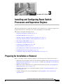
This chapter describes how to install and configure a route switch processor or supervisor engine. It also
provides instructions for connecting to the console and uplink ports on the module.
This chapter contains the following sections:
•
Preparing for Installation or Removal, page 3-1
•
Determining Module Location, page 3-3
•
Installing a Supervisor Engine or Route Switch Processor, page 3-4
•
Removing a Supervisor Engine or Route Switch Processor, page 3-7
•
Hot Swapping (OIR) Modules, page 3-8
•
Connecting to the Console Port, page 3-9
•
Connecting to the Uplink Ports, page 3-10
•
Using Flash Memory Cards, page 3-12
•
Power Management and Environmental Monitoring, page 3-14
•
Determining Software Feature Support, page 3-14
•
Configuring a Supervisor Engine or Route Switch Processor, page 3-14
Preparing for Installation or Removal
Before you attempt to install a supervisor engine or route switch processor in the router, be sure to:
•
Review the safety precautions and electrostatic discharge guidelines in the “Safety Precautions for
Module Installation and Removal” section on page 3-2 and the “Preventing Electrostatic Discharge
Damage” section on page 3-2.
•
Make sure you have on hand the tools required for the installation. (See the “Tools Required for
Module Installation” section on page 3-3.)
•
Determine which chassis slot to install the module in. (See the “Determining Module Location”
section on page 3-3.)
•
Consider cabling for the console and uplink ports. (See Appendix B, “Cable and Connector
Specifications.”)
Cisco 7600 Series Router Supervisor Engine and Route Switch Processor Guide
OL-10100-05
3-1
Chapter 3
Installing and Configuring Route Switch Processors and Supervisor Engines
Preparing for Installation or Removal
Safety Precautions for Module Installation and Removal
Be sure to observe the following warnings and safety precautions when you work on the router.
Warning
Hazardous voltage or energy is present on the backplane when the system is operating. Use caution
when servicing. Statement 1034
Warning
Hazardous network voltages are present in WAN ports regardless of whether power to the unit is OFF
or ON. To avoid electric shock, use caution when working near WAN ports. When detaching cables,
detach the end away from the unit first. Statement 1026
Warning
Invisible laser radiation may be emitted from disconnected fibers or connectors. Do not stare into
beams or view directly with optical instruments. Statement 1051
Warning
Blank faceplates and cover panels serve three important functions: they prevent exposure to
hazardous voltages and currents inside the chassis; they contain electromagnetic interference (EMI)
that might disrupt other equipment; and they direct the flow of cooling air through the chassis. Do not
operate the system unless all cards, faceplates, front covers, and rear covers are in place.
Statement 1029
Preventing Electrostatic Discharge Damage
Electrostatic discharge (ESD) damage, which can occur when electronic cards or components are
improperly handled, results in complete or intermittent failures. The supervisor engine or route switch
processor consists of printed circuit boards that are fixed in metal carriers. Electromagnetic interference
(EMI) shielding and connectors are integral components of the carrier. Although the metal carrier helps
to protect the boards from ESD, use a preventive antistatic strap during handling.
To prevent ESD damage, follow these guidelines whenever you handle supervisor engine or RSP
modules and router components:
•
Always use an ESD wrist or ankle strap and ensure that it makes good skin contact.
•
Connect the equipment end of the strap to an unfinished chassis surface.
•
When installing a component, use any available ejector levers or captive installation screws to
properly seat the bus connectors in the backplane or midplane. These devices prevent accidental
removal, provide proper grounding for the system, and help to ensure that bus connectors are
properly seated.
•
When removing a component, use any available ejector levers or captive installation screws to
release the bus connectors from the backplane or midplane.
•
Handle components by their handles or edges only; do not touch the printed circuit boards or
connectors.
•
Place a removed component board-side-up on an antistatic surface or in a static-shielding container.
If you plan to return the component to the factory, immediately place it in a static-shielding
container.
Cisco 7600 Series Router Supervisor Engine and Route Switch Processor Guide
3-2
OL-10100-05
Chapter 3
Installing and Configuring Route Switch Processors and Supervisor Engines
Determining Module Location
Caution
•
Avoid contact between the printed circuit boards and clothing. The wrist strap only protects
components from ESD voltages on the body; ESD voltages on clothing can still cause damage.
•
Never attempt to remove the printed circuit board from the metal carrier.
Periodically check the resistance value of the antistatic strap. The measurement should be within the
range of 1 and 10 megohms (Mohms).
Tools Required for Module Installation
These tools are required to install modules in the Cisco 7600 series router:
•
Flat-blade screwdriver
•
Antistatic wrist strap or other grounding device
•
Antistatic mat or antistatic foam
Determining Module Location
Determine which chassis slot to install the module in. Table 3-1 lists the chassis slots in which you can
install a supervisor engine or route switch processor.
Table 3-1
Supervisor Engine and Route Switch Processor Slot Assignments
Module
Slot Assignments
Route Switch Processor 720
(RSP720-10GE)
Route Switch Processor 720
(RSP720)
Supervisor Engine 720
(Sup720)
•
Slots 1 and 2 (3-slot enhanced [-S] chassis
and 4-slot chassis)
•
Slots 5 and 6 (6-slot and 9-slot enhanced [-S]
chassis and 9-slot chassis)
•
Not supported in the 3-slot, 6-slot, or 13-slot
chassis
•
Slots 1 and 2 (4-slot chassis)
•
Slots 5 and 6 (6-slot and 9-slot chassis,
including enhanced [-S] chassis)
•
Slots 7 and 8 (13-slot chassis)
•
Not supported in the 3-slot chassis
•
Slots 1 and 2 (3-slot and 4-slot chassis)
•
Slots 5 and 6 (6-slot and 9-slot chassis)
•
Slots 7 and 8 (13-slot chassis)
Cisco 7600 Series Router Supervisor Engine and Route Switch Processor Guide
OL-10100-05
3-3
Chapter 3
Installing and Configuring Route Switch Processors and Supervisor Engines
Installing a Supervisor Engine or Route Switch Processor
Table 3-1
Supervisor Engine and Route Switch Processor Slot Assignments (continued)
Module
Supervisor Engine 32
Supervisor Engine 2
Slot Assignments
•
Slots 1 and 2 (4-slot chassis)
•
Slots 5 and 6 (6-slot and 9-slot chassis)
•
Slots 7 and 8 (13-slot chassis)
•
Not supported in the 3-slot chassis
•
Slots 1 and 2 (all chassis)
•
Not supported in the 4-slot chassis
Installing a Supervisor Engine or Route Switch Processor
To install a supervisor engine or route switch processor module in the router, perform the following
steps:
Caution
Step 1
Step 2
To prevent ESD damage, handle modules by the carrier edges only.
Choose a slot for the module (see Table 3-1). Make sure that there is enough clearance to accommodate
any equipment that will be connected to the ports on the module. If possible, place modules between
empty slots that contain only blank module filler plates.
a.
If a blank module filler plate is installed in the slot in which you plan to install the module, remove
the plate by removing its two Phillips pan-head screws.
b.
If another module is installed in the slot, remove the module by following the procedure in the
“Removing a Supervisor Engine or Route Switch Processor” section on page 3-7.
Verify that the captive installation screws are tightened on all of the modules installed in the chassis.
This step ensures that the EMI gaskets on all modules are fully compressed in order to maximize the
opening space for the new or replacement module.
Note
Step 3
If the captive installation screws are loose, the EMI gaskets on the installed modules will push
adjacent modules toward the open slot, which reduces the opening size and makes it difficult to
install the new module.
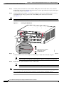
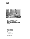
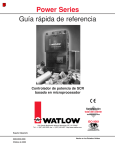
Fully open both ejector levers on the new module. (See Figure 3-1.)
Cisco 7600 Series Router Supervisor Engine and Route Switch Processor Guide
3-4
OL-10100-05
Chapter 3
Installing and Configuring Route Switch Processors and Supervisor Engines
Installing a Supervisor Engine or Route Switch Processor
TX
PO
R
T
4
R
X
C
AR
AL RIE
AR R
M
3
PO
R
T
Captive
installation
screws
45168
Ejector lever
Step 4
TX
R
X
AC
TIV
E
TX
R
X
AC
TIV
E
C
AR
AL RIE
AR R
M
2
PO
R
T
PO
R
T
1
C
AR
AL RIE
AR R
M
R
X
R
X
TX
TX
TX
R
X
TX
R
X
C
AR
AL RIE
AR R
M
4
LIN
K
4
3
LIN
K
1
LIN
K
4 PORT OC-12 POS MM
2
LIN
K
2
R
ES
ET
ST
AT
U
S
TX
1
3
AC
TIV
E
OSM-4OC12-POS-MM
AC
TIV
E
Ejector Levers and Captive Installation Screws
R
X
Figure 3-1
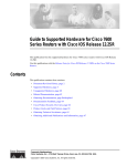
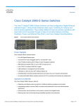
Position the module in the slot. Make sure that you align the sides of the module with the guides on each
side of the slot. (See Figure 3-2.)
Figure 3-2
Positioning the Module in the Slot
Insert module
between slot guides
EMI gasket
3
1
2
3
6
OSM-4OC12 POS-SI
1
WS-X6K-SUP2-2GE
ST
AT
US
SUPERVISOR2
SY
ST
3
LE
EM
CO
NSO
R
PW
M
G
M
T
RES
STA
ET
CONSOLE
CONSOLE
PORT
MODE
AC
VE
RX
TX
TX
ET
2
S
Switch
RE
100%
4
IR
LI
PCMCIA
NK
1
2 LIN
K
LI
NK
3
Load
AC
TI
VE
RX
TX
TX
RX
R
IE M
RR R
CA ALA
O
PORT 1 P
K
4 LIN
RT
AC
TI
VE
R
IE M
RR R
CA ALA
RX
TX
TX
RX
1
O
PORT 2 P
RT
TI
VE
RX
TX
TX
R
IE M
RR R
CA ALA
PO
RT
RX
3
R
IE M
RR R
CA ALA
PO
RT4
1%
1
TU
3
AC
TI
S
4 PORT OC-12 POS SM
AC
RX
2
EJECT
OSM-4OC12 POS-SI
STA
TI
S
TU
4 PORT OC-12 POS SM
VE
RX
TX
TX
2
RE
4
IR
LI
NK
1
2 LIN
K
LI
NK
3
K
4 LIN
SE
AC
TI
R
IE M
RR R
CA ALA
VE
NK
LI X
R
TX
TX
RX
T
PO
RT
1
AC
TI
VE
RX
TX
TX
RX
R
IE M
RR R
CA ALA
PO
RT
2
AC
TI
VE
RX
TX
TX
RX
R
IE M
RR R
CA ALA
PO
RT
3
RX
R
IE M
RR R
CA ALA
PO
RT4
Ejector lever fully
extended
63677
EMI gasket
Cisco 7600 Series Router Supervisor Engine and Route Switch Processor Guide
OL-10100-05
3-5
Chapter 3
Installing and Configuring Route Switch Processors and Supervisor Engines
Installing a Supervisor Engine or Route Switch Processor
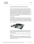
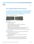
Step 5
Carefully slide the module into the slot until the EMI gasket on the module makes contact with the
module in the adjacent slot and both ejector levers have closed to approximately 45 degrees with respect
to the module faceplate. (See Figure 3-3.)
Step 6
Using the thumb and forefinger of each hand, grasp the two ejector levers and press down to create a
small (0.040 inch [1 mm]) gap between the module EMI gasket and the adjacent module.
(See Figure 3-3.)
Caution
Do not press down too forcefully on the ejector levers. They will bend and be damaged.
Figure 3-3
Clearing the EMI Gasket
Press down
Press down
WS-X6K-SUP2-2GE
T
M
LE
G
US
O
EM
M
T
AT
ST
NS
R
SE
ST
SY
CO
PW
RE
Switch
100%
CONSOLE
PORT
MODE
CONSOLE
SUPERVISOR2
Load
PORT 1
PCMCIA
PORT 2
EJECT
1%
OSM-4OC12 POS-SI
1
NK
LI
3
ST
AT
T
AC
IV
RX
TX
TX
US
2
4 PORT OC-12 POS
RE
4
SM IR
LIN
K
1
2 LIN
K
LIN
K
3
4 LIN
SE
NK
LI
E
AC
TIV
E
RX
TX
TX
RX
T
R
IE M
RR AR
CA AL
PO
RT
AC
TIV
E
RX
R
IE M
RR AR
CA AL
K
TX
TX
RX
1
PO
RT
AC
TIV
E
RX
TX
TX
RX
2
R
IE M
RR AR
CA AL
PO
RT
RX
3
R
IE M
RR AR
CA AL
PO
RT
4
RT
4
OSM-4OC12 POS-SI
1
ST
AT
3
AC
TIV
4 PORT OC-12 POS
E
RX
TX
TX
US
2
RE
4
SM IR
LIN
K
1
2 LIN
K
LIN
K
3
4 LIN
K
SE
AC
TIV
R
IE M
RR AR
CA AL
RX
TX
TX
RX
T
E
PO
RT
1
AC
TIV
E
RX
TX
TX
RX
R
IE M
RR AR
CA A L
PO
RT
2
AC
TIV
E
RX
TX
TX
RX
R
IE M
RR AR
CA AL
PO
RT
3
RX
R
IE M
RR AR
CA AL
PO
5
1mm Gap between the module
EMI gasket and the
module above it.
63678
4
6
Step 7
While pressing down, simultaneously close both ejector levers to fully seat the module in the backplane
connector. The ejector levers are fully closed when they are flush with the module faceplate.
Note
Step 8
Tighten the two captive installation screws on the module.
Note
Note
Failure to fully seat the module in the backplane connector can result in error messages.
Make sure the ejector levers are fully closed before tightening the captive installation screws.
Blank module filler plates (Cisco part number 800-00292-01) should be installed in any empty chassis
slots to keep dust out of the chassis and to maintain consistent airflow through the chassis.
Cisco 7600 Series Router Supervisor Engine and Route Switch Processor Guide
3-6
OL-10100-05
Chapter 3
Installing and Configuring Route Switch Processors and Supervisor Engines
Removing a Supervisor Engine or Route Switch Processor
Removing a Supervisor Engine or Route Switch Processor
Before you remove a supervisor engine or route switch processor (RSP) from the router, you should first
save the current configuration using the write {host file | network | terminal} command. This step saves
time when bringing the module back online. You can recover the configuration by downloading it from
the server to the nonvolatile memory of the supervisor engine or RSP.
If the module is running Cisco IOS software, save the current running configuration by entering the
copy running-config startup-config command.
Warning
Hazardous voltage or energy is present on the backplane when the system is operating. Use caution
when servicing. Statement 1034
Warning
Invisible laser radiation may be emitted from disconnected fibers or connectors. Do not stare into
beams or view directly with optical instruments. Statement 1051
To remove a supervisor engine or RSP, perform these steps:
Step 1
Disconnect any cables attached to ports on the module.
Step 2
Verify that the captive installation screws on all of the modules in the chassis are tight. This step assures
that the space created by the removed module is maintained.
Note
If the captive installation screws are loose, the EMI gaskets on the installed modules will push
the modules toward the open slot, which reduces the opening size and makes it difficult to
remove the module.
Step 3
Loosen the two captive installation screws on the module you plan to remove from the chassis.
Step 4
Place your thumbs on the ejector levers (see Figure 3-1) and simultaneously rotate the ejector levers
outward to unseat the module from the backplane connector.
Step 5
Grasp the front edge of the module and slide the module straight out of the slot. If the chassis has
horizontal slots, place your hand under the module to support its weight as you slide it out from the slot.
Do not touch the module circuitry.
Caution
To prevent ESD damage, handle modules by the carrier edges only.
Step 6
Place the module on an antistatic mat or antistatic foam, or immediately reinstall the module in another slot.
Step 7
Install blank module filler plates (Cisco part number 800-00292-01) in any empty slots to keep dust out
of the chassis and to maintain consistent airflow through the chassis.
Warning
Blank faceplates and cover panels serve three important functions: they prevent exposure to
hazardous voltages and currents inside the chassis; they contain electromagnetic interference (EMI)
that might disrupt other equipment; and they direct the flow of cooling air through the chassis. Do not
operate the system unless all cards, faceplates, front covers, and rear covers are in place.
Statement 1029
Cisco 7600 Series Router Supervisor Engine and Route Switch Processor Guide
OL-10100-05
3-7
Chapter 3
Installing and Configuring Route Switch Processors and Supervisor Engines
Hot Swapping (OIR) Modules
Hot Swapping (OIR) Modules
Cisco 7600 series routers provide a feature that allows you to remove and replace a redundant
supervisor engine or route switch processor (and other redundant cards) without powering down the
router. This feature, called hot swapping or online insertion and removal (OIR), allows you to remove
and replace a redundant module without disrupting router operation.
When two redundant modules are installed in the router, only one of the modules is active at a time. The
other one runs in standby mode, ready to take over processing if the active module fails.
When you remove or insert a redundant module while the router is powered on and running, the router
does the following:
1.
Determines if there is sufficient power for the module.
2.
Scans the backplane for configuration changes.
3.
Initializes the newly inserted module. In addition, the system notes any removed modules and places
those modules in the administratively shutdown state.
4.
Places any previously configured interfaces on the module back to the state they were in when they
were removed. Any newly inserted interfaces are put in the administratively shutdown state, as if
they were present (but unconfigured) at boot time. If you insert the same type of module into a slot,
its ports are configured and brought online up to the port count of the original module.
The router runs diagnostic tests on any new interfaces and the test results indicate the following:
Caution
•
If the tests pass, the router is operating normally.
•
If the new module is faulty, the router resumes normal operation but leaves the new interfaces
disabled.
•
If the diagnostic tests fail, the router stops operating, which usually indicates that the new module
has a problem in the bus and should be removed.
To avoid erroneous failure messages, note the current configuration of all interfaces before you remove
or replace another module, and allow at least 15 seconds for the system to reinitialize after a module has
been removed or replaced.
Removing and Replacing Memory
The multilayer switch feature card (MSFC4) on the RSP720 supports several configurable options for
dynamic random-access memory (DRAM). The router uses this memory to store routing tables,
protocols, and network accounting applications. The DRAM resides on four dual in-line memory
modules (DIMMs), which you can remove and replace in order to upgrade the module with more
memory or to replace failed memory.
Note
If you are replacing DRAM on an existing MSFC4, upload your current configuration file to a remote
server before you remove the memory. Otherwise, you will have to re-enter all your current configuration
information manually after you replace the memory.
Cisco 7600 Series Router Supervisor Engine and Route Switch Processor Guide
3-8
OL-10100-05
Chapter 3
Installing and Configuring Route Switch Processors and Supervisor Engines
Connecting to the Console Port
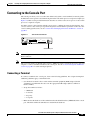
Connecting to the Console Port
The console port allows you to access the router either locally (with a console terminal) or remotely (with a
modem). The console port is located on the front panel of the route switch processor or supervisor engine (see
Figure 3-4). This section provides information about how to connect to the console port on a route switch
processor or supervisor engine.
You must connect to the router through the console port to configure the router for the first time. You
can also connect to the console port to perform diagnostics and troubleshoot problems on the router. For
console cabling specifications, see the “Console Port Cabling Specifications and Pinouts” section on
page B-6.
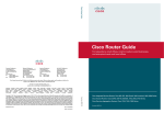
Figure 3-4
Console Port Connector
DISK 0
EJECT
RE
SE
T
153653
CONSOLE
DISK 1
EJECT
CONSOLE port
Note
The console port is an EIA/TIA-232 asynchronous, serial connection with hardware flow control and an
RJ-45 connector.
Note
The accessories kit that is shipped with your Cisco 7600 series router contains the necessary cable and
adapters to connect a terminal or modem to the console port. See the “Console Port Signals and Pinouts”
section on page B-7 for cable and adapter pinouts.
Connecting a Terminal
To connect a terminal to the console port, observe the following guidelines. For a Supervisor Engine 2
additional guidelines apply, as described below.
•
Use the RJ-45-to-RJ-45 rollover cable and data terminal equipment (DTE) adapter (labeled
“Terminal”) provided with the router. Use the appropriate DTE adapter (RJ-45-to-DB-25 or
RJ-45-to-DB-9).
•
Set up the terminal as follows:
– 9600 baud
– 8 data bits
– No parity
– 2 stop bits
•
Make sure that the baud rate of the terminal matches the default baud rate (9600 baud) of the console
port. Check the terminal documentation to determine the baud rate.
Cisco 7600 Series Router Supervisor Engine and Route Switch Processor Guide
OL-10100-05
3-9
Chapter 3
Installing and Configuring Route Switch Processors and Supervisor Engines
Connecting to the Uplink Ports
Supervisor Engine 2
In addition to the above configuration requirements, note that with a Supervisor Engine 2 you can use
two types of console cables to connect a terminal to the console port. To accommodate either type of
cable, set the console port mode switch (to the right of the console port) as follows:
Note
•
To use the RJ-45-to-RJ-45 rollover cable and DTE adapter (labeled “Terminal”) provided with the
router, make sure that the console port mode switch is in the in position (factory default).
•
To use a Catalyst 5000 Supervisor Engine III console cable and adapter (not provided), make sure
that the console port mode switch is in the out position, and use the appropriate adapter for the
terminal connection. See the “Console Port Mode 2 Signaling and Pinouts (Sup2 Only)” section on
page B-10 for a list of console port pinouts when the switch is in the out position.
To access the console port mode switch, use a ballpoint pen tip or other small, pointed object.
Connecting a Modem
To connect a modem to the console port, observe the following guidelines:
•
Use the RJ-45-to-RJ-45 rollover cable and the RJ-45-to-DB-25 data communications equipment
(DCE) adapter (labeled “Modem”) provided with the router.
•
On a Supervisor Engine 2, make sure that the console port mode switch is in the in position (factory
default).
Connecting to the Uplink Ports
The supervisor engine and route switch processor have uplink ports that you use to connect the router to
other network devices. You can configure the ports with small form-factor pluggable (SFP), XENPAK,
X2, or Gigabit Interface Converter (GBIC) optics modules.
Table 3-2 lists the different types of uplink ports on each module. SFP, XENPAK, and X2 optics modules
have SC, LC, or MT-RJ connectors. GBIC modules (on the Supervisor Engine 2) have SC connectors.
Warning
Caution
Invisible laser radiation may be emitted from disconnected fibers or connectors. Do not stare into
beams or view directly with optical instruments. Statement 1051
Do not remove the plugs from the optical bores on the fiber-optic cable or the module port or until you
are ready to connect the cable. The plugs protect the optical bores and cable from contamination.
Cisco 7600 Series Router Supervisor Engine and Route Switch Processor Guide
3-10
OL-10100-05
Chapter 3
Installing and Configuring Route Switch Processors and Supervisor Engines
Connecting to the Uplink Ports
Table 3-2
Route Switch Processor and Supervisor Engine Uplink Ports
Module
Uplink Ports
Route Switch
Processor 720
Two 10/100/1000 BASE-T Gigabit Ethernet uplink ports:
RSP720-10GE
•
Port 1 requires that a 1-Gbps SFP module be installed.
•
Port 2 supports either a 1-Gbps SFP module or a 10/100/1000-Mbps RJ-45
connector.
Three Gigabit Ethernet uplink ports (1 gigabit per second [Gbps]):
•
Ports 1 and 2 require that a 1-Gbps SFP module be installed.
•
Port 3 supports either a 10/100/1000-Mbps RJ-45 connector.
Note
Use Category 5 Shielded Twisted Pair cable at port 3.
Two 10 Gigabit Ethernet uplink ports (10 Gbps):
•
Supervisor Engine 720
Supervisor Engine 32
Supervisor Engine 2
Ports 4 and 5 require that a 10-Gbps X2 optics module be installed.
Two Gigabit Ethernet uplink ports:
•
Port 1 requires that a 1-Gbps SFP module be installed.
•
Port 2 supports either a 1-Gbps SFP module or a 10/100/1000-Mbps RJ-45
connector.
•
The WS-SUP32-GE-3B provides one 10/100/1000-Mbps RJ-45 uplink
port and eight Gigabit Ethernet uplink ports. The Gigabit Ethernet uplink
ports require SFP modules to be installed into them.
•
The WS-SUP32-10GE-3B provides one 10/100/1000-Mbps uplink port
and two 10-Gigabit Ethernet uplink ports. The Gigabit Ethernet uplink
ports require XENPAK optics modules to be installed into them. The ports
operate at 10 Gbps.
•
Two dual-port Gigabit Ethernet ports operate in full-duplex mode only.
•
You can configure the ports with any combination of copper,
short-wave (SX), long-wave/long-haul (LX/LH), extended-reach (ZX), and
coarse wavelength-division multiplexing (CWDM) 1000BASE-X GBICs.
To connect to the module uplink ports, follow these steps:
Step 1
If necessary, install an optics modules in the empty slots on the front panel.
Note
The Sup720 and RSP720 provide two connectors for port 2; however, you can use only one of
the connectors at a time. (Note that the RSP720-10GE provides only one port 2 connector.)
Step 2
Remove the plugs from the uplink ports and store them for future use.
Step 3
Remove the plugs from the connector on the fiber-optic cable.
Step 4
Insert the cable connector into the uplink port and make sure that both the transmit (Tx) and receive (Rx)
fiber-optic cables are fully inserted into the connector.
Step 5
(Sup2 only) If you are using the LX/LH GBIC with multimode fiber (MMF), you need to install a patch
cord between the GBIC and the MMF cable. For instructions, see the “Patch Cord” section on page B-16.
Cisco 7600 Series Router Supervisor Engine and Route Switch Processor Guide
OL-10100-05
3-11
Chapter 3
Installing and Configuring Route Switch Processors and Supervisor Engines
Using Flash Memory Cards
Note
•
If two RSPs or supervisor engines are installed, the uplink ports on the redundant (standby) module
are active and can be used for normal traffic like any other ports in the chassis.
•
In Cisco IOS Release 12.2SRC, the uplink ports on a standby RSP720-10GE are not active and
cannot be used for normal traffic.
Using Flash Memory Cards
The front panel on the supervisor engine or route switch processor has one or two disk slots for flash
memory cards. You can insert a Flash PC, CompactFlash, or MicroDrive memory card in the slot and
use the card to store and run software images and configuration files or to serve as an I/O device.
See Table 3-3 for memory options.
•
The Route Switch Processor 720 with 10-GE uplink ports (RSP720-10GE) has a single disk slot
(labeled DISK 0) that accepts CompactFlash cards.
•
The Route Switch Processor 720 and Supervisor Engine 720 have two disk slots:
– DISK 0 accepts a CompactFlash card only.
– DISK 1 accepts either a CompactFlash card or a 1-GB MicroDrive.
Note
•
The Supervisor Engine 32 has a single slot (labeled DISK 0) that accepts CompactFlash cards and
IBM MicroDrive cards.
•
The Supervisor Engine 2 has a single slot (labeled PCMCIA) that accepts PCMCIA cards.
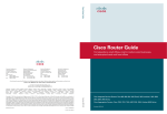
You can insert and remove a flash memory card with the power on. Before you install a card, verify that
the card is set with write protection off. The write-protection switch is located on the front edge of the
card (when the printing is right side up and the edge connector end is away from you). (See Figure 3-5.)
Figure 3-5
Locating the Flash PC Card Write-Protection Switch
Flash PC card
shown with write
protection off
H2352
Flash PC card
write protection
Flash PC card
Note
Not all flash memory cards have a write-protection switch.
Cisco 7600 Series Router Supervisor Engine and Route Switch Processor Guide
3-12
OL-10100-05
Chapter 3
Installing and Configuring Route Switch Processors and Supervisor Engines
Using Flash Memory Cards
Table 3-3 lists the Cisco product numbers of memory cards supported on Cisco 7600 supervisor engines
and route switch processors.
Table 3-3
CompactFlash Memory Cards
Product Number
Description
RSP720 and RSP720-10GE Flash Memory Cards
MEM-RSP720-CF256M
Cisco CompactFlash Memory Card, 256 MB
MEM-RSP720-CF512M
Cisco CompactFlash Memory Card, 512 MB
MEM-RSP720-CF1G
Cisco CompactFlash Memory Card, 1 GB
Sup720 and Sup32 Flash Memory Cards
MEM-C6K-CPTFL64M
Cisco CompactFlash Memory Card, 64 MB
MEM-C6K-CPTFL128M
Cisco CompactFlash Memory Card, 128 MB
MEM-C6K-CPTFL256M
Cisco CompactFlash Memory Card, 256 MB
MEM-C6K-CPTFL512M
Cisco CompactFlash Memory Card, 512 MB
Sup2 Flash Memory Cards
MEM-C6K-ATA-1-64M
Cisco ATA Type 1 Flash Memory Card, 64 MB
Installing a Flash Memory Card
To install a flash memory card, follow these steps:
Step 1
Hold the memory card with the connector end of the card toward the slot. The connector end of the card is
opposite the end with the write-protection switch (if there is one), which is shown in Figure 3-5.
Step 2
Slide the card into the slot until the device completely seats in the connector at the back of the slot and
the ejector button pops out toward you.
Caution
Step 3
Note
Do not attempt to force the memory card fully into the slot or you could damage the connector pins.
When correctly inserted, a portion of the device remains outside the slot.
Format the memory card the first time that it is installed in the system.
Be sure to format the memory card with the type of supervisor engine or route switch processor that the
card is being used with. A memory card formatted for one type of supervisor engine or route switch
processor may not work with another type.
Cisco 7600 Series Router Supervisor Engine and Route Switch Processor Guide
OL-10100-05
3-13
Chapter 3
Installing and Configuring Route Switch Processors and Supervisor Engines
Power Management and Environmental Monitoring
Removing a Flash Memory Card
Caution
Do not remove a flash memory card while its LED light is on or the file may become corrupted.
To remove a flash memory card, follow these steps:
Step 1
Make sure that the Disk LED is off (no operations are in progress).
Step 2
Press the ejector button to disconnect the memory card from the connector at the back of the slot.
Step 3
Remove the memory card from the slot and place it in an antistatic bag.
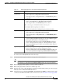
Power Management and Environmental Monitoring
For detailed information on power management and environmental monitoring, see the Cisco 7600
Series Router Cisco IOS Software Configuration Guide.
Determining Software Feature Support
This section describes the Feature Navigator and Software Advisor tools. You can use these tools to
determine which features are supported on the router and the minimum Cisco IOS software requirements
for the hardware installed on your router.
Note
You must have an account on Cisco.com to access the Feature Navigator or Software Advisor tool.
•
To determine which software features are supported by your route switch processor or supervisor
engine, use the Feature Navigator tool at the following URL:
http://tools.cisco.com/ITDIT/CFN/jsp/index.jsp
•
To check the minimum Cisco IOS software requirements for the hardware installed on your router,
use the Software Advisor tool at the following URL:
http://www.cisco.com/public/support/tac/tools.shtml
This tool does not verify whether the line cards in a system are compatible, but it does provide the
minimum Cisco IOS requirements for individual line cards, modules, or options.
Configuring a Supervisor Engine or Route Switch Processor
See the Cisco 7600 Series Router Cisco IOS Software Configuration Guide for information about how
to configure the supervisor engine or route switch processor for operation.
Cisco 7600 Series Router Supervisor Engine and Route Switch Processor Guide
3-14
OL-10100-05