1
Cisco 7600 Series Router
Supervisor Engine and
Route Switch Processor Guide
January 2008
Americas Headquarters
Cisco Systems, Inc.
170 West Tasman Drive
San Jose, CA 95134-1706
USA
http://www.cisco.com
Tel: 408 526-4000
800 553-NETS (6387)
Fax: 408 527-0883
Text Part Number: OL-10100-04
THE SPECIFICATIONS AND INFORMATION REGARDING THE PRODUCTS IN THIS MANUAL ARE SUBJECT TO CHANGE WITHOUT NOTICE. ALL
STATEMENTS, INFORMATION, AND RECOMMENDATIONS IN THIS MANUAL ARE BELIEVED TO BE ACCURATE BUT ARE PRESENTED WITHOUT
WARRANTY OF ANY KIND, EXPRESS OR IMPLIED. USERS MUST TAKE FULL RESPONSIBILITY FOR THEIR APPLICATION OF ANY PRODUCTS.
THE SOFTWARE LICENSE AND LIMITED WARRANTY FOR THE ACCOMPANYING PRODUCT ARE SET FORTH IN THE INFORMATION PACKET THAT
SHIPPED WITH THE PRODUCT AND ARE INCORPORATED HEREIN BY THIS REFERENCE. IF YOU ARE UNABLE TO LOCATE THE SOFTWARE LICENSE
OR LIMITED WARRANTY, CONTACT YOUR CISCO REPRESENTATIVE FOR A COPY.
The following information is for FCC compliance of Class A devices: This equipment has been tested and found to comply with the limits for a Class A digital device, pursuant
to part 15 of the FCC rules. These limits are designed to provide reasonable protection against harmful interference when the equipment is operated in a commercial
environment. This equipment generates, uses, and can radiate radio-frequency energy and, if not installed and used in accordance with the instruction manual, may cause
harmful interference to radio communications. Operation of this equipment in a residential area is likely to cause harmful interference, in which case users will be required
to correct the interference at their own expense.
The following information is for FCC compliance of Class B devices: The equipment described in this manual generates and may radiate radio-frequency energy. If it is not
installed in accordance with Cisco’s installation instructions, it may cause interference with radio and television reception. This equipment has been tested and found to
comply with the limits for a Class B digital device in accordance with the specifications in part 15 of the FCC rules. These specifications are designed to provide reasonable
protection against such interference in a residential installation. However, there is no guarantee that interference will not occur in a particular installation.
Modifying the equipment without Cisco’s written authorization may result in the equipment no longer complying with FCC requirements for Class A or Class B digital
devices. In that event, your right to use the equipment may be limited by FCC regulations, and you may be required to correct any interference to radio or television
communications at your own expense.
You can determine whether your equipment is causing interference by turning it off. If the interference stops, it was probably caused by the Cisco equipment or one of its
peripheral devices. If the equipment causes interference to radio or television reception, try to correct the interference by using one or more of the following measures:
• Turn the television or radio antenna until the interference stops.
• Move the equipment to one side or the other of the television or radio.
• Move the equipment farther away from the television or radio.
• Plug the equipment into an outlet that is on a different circuit from the television or radio. (That is, make certain the equipment and the television or radio are on circuits
controlled by different circuit breakers or fuses.)
Modifications to this product not authorized by Cisco Systems, Inc. could void the FCC approval and negate your authority to operate the product.
The Cisco implementation of TCP header compression is an adaptation of a program developed by the University of California, Berkeley (UCB) as part of UCB’s public
domain version of the UNIX operating system. All rights reserved. Copyright © 1981, Regents of the University of California.
NOTWITHSTANDING ANY OTHER WARRANTY HEREIN, ALL DOCUMENT FILES AND SOFTWARE OF THESE SUPPLIERS ARE PROVIDED “AS IS” WITH
ALL FAULTS. CISCO AND THE ABOVE-NAMED SUPPLIERS DISCLAIM ALL WARRANTIES, EXPRESSED OR IMPLIED, INCLUDING, WITHOUT
LIMITATION, THOSE OF MERCHANTABILITY, FITNESS FOR A PARTICULAR PURPOSE AND NONINFRINGEMENT OR ARISING FROM A COURSE OF
DEALING, USAGE, OR TRADE PRACTICE.
IN NO EVENT SHALL CISCO OR ITS SUPPLIERS BE LIABLE FOR ANY INDIRECT, SPECIAL, CONSEQUENTIAL, OR INCIDENTAL DAMAGES, INCLUDING,
WITHOUT LIMITATION, LOST PROFITS OR LOSS OR DAMAGE TO DATA ARISING OUT OF THE USE OR INABILITY TO USE THIS MANUAL, EVEN IF CISCO
OR ITS SUPPLIERS HAVE BEEN ADVISED OF THE POSSIBILITY OF SUCH DAMAGES.
CCVP, the Cisco logo, and the Cisco Square Bridge logo are trademarks of Cisco Systems, Inc.; Changing the Way We Work, Live, Play, and Learn is a service mark of Cisco Systems,
Inc.; and Access Registrar, Aironet, BPX, Catalyst, CCDA, CCDP, CCIE, CCIP, CCNA, CCNP, CCSP, Cisco, the Cisco Certified Internetwork Expert logo, Cisco IOS, Cisco Press,
Cisco Systems, Cisco Systems Capital, the Cisco Systems logo, Cisco Unity, Enterprise/Solver, EtherChannel, EtherFast, EtherSwitch, Fast Step, Follow Me Browsing,
FormShare, GigaDrive, HomeLink, Internet Quotient, IOS, iPhone, IP/TV, iQ Expertise, the iQ logo, iQ Net Readiness Scorecard, iQuick Study, LightStream, Linksys,
MeetingPlace, MGX, Networking Academy, Network Registrar, Packet, PIX, ProConnect, ScriptShare, SMARTnet, StackWise, The Fastest Way to Increase Your Internet
Quotient, and TransPath are registered trademarks of Cisco Systems, Inc. and/or its affiliates in the United States and certain other countries.
All other trademarks mentioned in this document or Website are the property of their respective owners. The use of the word partner does not imply a partnership relationship
between Cisco and any other company. (0705R)
Any Internet Protocol (IP) addresses used in this document are not intended to be actual addresses. Any examples, command display output, and figures included in the
document are shown for illustrative purposes only. Any use of actual IP addresses in illustrative content is unintentional and coincidental.
Cisco 7600 Series Router Supervisor Engine and Route Switch Processor Guide
Copyright © 2007-2008 Cisco Systems, Inc. All rights reserved.
C O N T E N T S
Preface
vii
Contents
vii
Document History
vii
Document Organization
viii
Document Conventions viii
Warning Definition ix
Related Documentation
ix
Obtaining Documentation, Obtaining Support, and Security Guidelines
CHAPTER
1
Cisco 7600 Product Overview
x
1-1
Cisco 7600 Series Routers 1-1
Supported Hardware 1-2
Features 1-3
Port Addresses 1-5
Physical Interface Addresses
MAC Addresses 1-6
CHAPTER
2
1-5
Route Switch Processors and Supervisor Engines
Overview
2-1
2-2
Route Switch Processor 720 2-6
RSP720 Features 2-7
Supported Chassis, Line Cards, and Modules
Unsupported Hardware and Features 2-7
2-7
RSP720 with 10GE Uplink Ports 2-8
RSP720-10GE Features 2-8
Supported Chassis, Line Cards, and Modules 2-9
RSP720-10GE Usage Guidelines and Limitations 2-10
QoS on the RSP720-10GE 2-10
Supervisor Engine 720 and Supervisor Engine 32 2-12
Front-Panel Controls (RSP720, RSP720-10GE, Sup720, Sup32) 2-12
Front-Panel LEDs (RSP720, RSP720-10GE, Sup720, Sup32) 2-13
Cisco 7600 Series Router Supervisor Engine and Route Switch Processor Guide
OL-10100-04
iii
Contents
Supervisor Engine 2
CHAPTER
2-14
Installing and Configuring Route Switch Processors and Supervisor Engines
3
Preparing for Installation or Removal 3-1
Safety Precautions for Module Installation and Removal
Preventing Electrostatic Discharge Damage 3-2
Tools Required for Module Installation 3-3
Determining Module Location
3-2
3-3
Installing a Supervisor Engine or Route Switch Processor
3-4
Removing a Supervisor Engine or Route Switch Processor
3-7
Hot Swapping (OIR) Modules
3-1
3-8
Removing and Replacing Memory
3-8
Connecting to the Console Port 3-9
Connecting a Terminal 3-9
Connecting a Modem 3-10
Connecting to the Uplink Ports
3-10
Using Flash Memory Cards 3-12
Installing a Flash Memory Card 3-13
Removing a Flash Memory Card 3-14
Power Management and Environmental Monitoring
Determining Software Feature Support
3-14
3-14
Configuring a Supervisor Engine or Route Switch Processor
APPENDIX
A
Technical Specifications
Module Specifications
A-1
A-1
Regulatory Standards Compliance
APPENDIX
B
3-14
Cable and Connector Specifications
Limiting Connection Distances
A-1
B-1
B-1
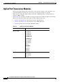
Uplink Port Transceiver Modules B-2
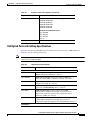
1GE Uplink Ports and Cabling Specifications B-3
10GE Uplink Ports and Cabling Specifications B-5
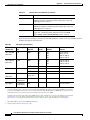
GBIC Module Cabling Specifications B-6
Console Port Cabling Specifications and Pinouts
Console Port Cabling Specifications B-6
Console Port Signals and Pinouts B-7
B-6
Cisco 7600 Series Router Supervisor Engine and Route Switch Processor Guide
iv
OL-10100-04
Contents
Identifying a Rollover Cable B-7
DB-9 Adapter (for Connecting to a PC) B-8
DB-25 Adapter (for Connecting to a Terminal) B-9
Modem Adapter B-9
Console Port Mode 2 Signaling and Pinouts (Sup2 Only) B-10
RJ-45 Connector
B-10
Fiber-Optic Connectors B-12
SC Connectors B-12
MT-RJ Connectors B-13
LC Connectors B-14
Cleaning the Fiber-Optic Connectors
B-15
LX/LH GBIC and MMF Cable Considerations B-16
Patch Cord B-16
Patch Cord Configuration Example B-16
Patch Cord Installation B-17
INDEX
Cisco 7600 Series Router Supervisor Engine and Route Switch Processor Guide
OL-10100-04
v
Contents
Cisco 7600 Series Router Supervisor Engine and Route Switch Processor Guide
vi
OL-10100-04
Preface
This guide describes the route switch processors and supervisor engines supported by Cisco 7600 series
routers. It also provides technical specifications for these modules and describes cable and connector
specifications.
Caution
Only trained and qualified service personnel (as defined in IEC 60950 and AS/NZS3260) should install,
replace, or service the equipment described in this document.
Contents
This preface contains the following sections:
•
Document History, page vii
•
Document Organization, page viii
•
Document Conventions, page viii
•
Related Documentation, page ix
•
Obtaining Documentation, Obtaining Support, and Security Guidelines, page x
Document History
Table 1 lists the technical changes made to this document since it was first printed.
Table 1
Document History
Revision
Date
Change Summary
OL-10100-04
January 2008
Added information about the Route Switch Processor 720 with
10-GE uplink ports, introduced in Cisco IOS Release 12.2SRC.
OL-10100-03
May 2007
Removed eFSU from the list of unsupported features for the Route
Switch Processor 720. Beginning in Cisco IOS Release 12.2SRB1,
eFSU and ISSU are supported on the RSP720, Sup720, and Sup32.
Added a note that Cisco IOS Release 12.2SXF is the last release in
which the Supervisor Engine 720 (with PFC3A) is supported.
Cisco 7600 Series Router Supervisor Engine and Route Switch Processor Guide
OL-10100-04
vii
Preface
Document Organization
Table 1
Document History (continued)
Revision
Date
Change Summary
OL-10100-02
February 2007
Added information about the Route Switch Processor 720 (a new
supervisor engine) introduced in Cisco IOS Release 12.2SRB.
OL-10100-01
May 2006
Initial release of the document.
Document Organization
This document is organized as follows:
Chapter
Title
Description
Chapter 1
Cisco 7600 Product
Overview
Provides an overview of Cisco 7600 series routers, and
interface and port addresses.
Chapter 2
Route Switch Processors
and Supervisor Engines
Describes the route switch processors (RSPs) and
supervisor engines supported on Cisco 7600 series routers.
Chapter 3
Installing and Configuring
Route Switch Processors
and Supervisor Engines
Provides instructions for installing and removing RSPs
and supervisor engines and connecting to the console
and uplink ports.
Appendix A
Technical Specifications
Lists the technical specifications for the RSP and
supervisor engines.
Appendix B
Cable and Connector
Specifications
Lists the cable and connector specifications for the
RSPs and supervisor engines.
Document Conventions
This document uses the following conventions:
Caution
Note
Convention
Description
boldface font
Commands, command options, and keywords are in boldface.
italic font
Command arguments for which you supply values are in italics.
Means reader be careful. You are capable of doing something that might result in equipment damage or
loss of data.
Means reader take note. Notes contain helpful suggestions or references to materials not contained in
this document.
Cisco 7600 Series Router Supervisor Engine and Route Switch Processor Guide
viii
OL-10100-04
Preface
Related Documentation
Warning Definition
Warning
IMPORTANT SAFETY INSTRUCTIONS
This warning symbol means danger. You are in a situation that could cause bodily injury. Before you
work on any equipment, be aware of the hazards involved with electrical circuitry and be familiar
with standard practices for preventing accidents. Use the statement number provided at the end of
each warning to locate its translation in the translated safety warnings that accompanied this
device. Statement 1071
SAVE THESE INSTRUCTIONS
See Regulatory Compliance and Safety Information for the Cisco 7600 Series Routers for translations of
warnings and information about the compliance and safety standards with which Cisco 7600 series
routers conform.
Related Documentation
The following documents provide additional information about Cisco 7600 series routers:
•
Cisco 7600 Series Routers Documentation Roadmap
•
Supported Hardware for Cisco 7600 Series Routers
•
Regulatory Compliance and Safety Information for the Cisco 7600 Series Routers
•
Cisco 7600 Series Router Installation Guide
•
Cisco 7609 Router Installation Guide (OSR-7609)
•
Cisco 7600 Series Router Module Installation Guide
•
Cisco 7600 Series Router Cisco IOS Command Reference
•
Cisco 7600 Series Router Cisco IOS System Message Guide
•
Cisco 7600 Series Router Cisco IOS Software Configuration Guide
Documentation for the Cisco 7600 series router is available online at the folowing URL:
http://www.cisco.com/en/US/products/hw/routers/ps368/tsd_products_support_series_home.html
For information about MIBs, refer to this URL:
http://www.cisco.com/public/sw-center/netmgmt/cmtk/mibs.shtml
Cisco 7600 Series Router Supervisor Engine and Route Switch Processor Guide
OL-10100-04
ix
Preface
Obtaining Documentation, Obtaining Support, and Security Guidelines
Obtaining Documentation, Obtaining Support, and Security
Guidelines
For information on obtaining documentation, obtaining support, providing documentation feedback,
security guidelines, and also recommended aliases and general Cisco documents, see the monthly
What’s New in Cisco Product Documentation, which also lists all new and revised Cisco technical
documentation, at:
http://www.cisco.com/en/US/docs/general/whatsnew/whatsnew.html
Cisco 7600 Series Router Supervisor Engine and Route Switch Processor Guide
x
OL-10100-04
CH A P T E R
1
Cisco 7600 Product Overview
This chapter provides an overview of the Cisco 7600 series routers and describes interface and port
addresses on the routers. It contains the following sections:
Note
•
Cisco 7600 Series Routers, page 1-1
•
Port Addresses, page 1-5
This document does not contain instructions for installing the router. For instructions on how to install
the router, see the Cisco 7600 Series Router Installation Guide.
Cisco 7600 Series Routers
The Cisco 7600 series routers consist of these routers:
Note
•
Cisco 7603 router (3 slots)
•
Cisco 7604 router (4 slots)
•
Cisco 7606 router (6 slots)
•
Cisco 7609 router (9 vertical slots)
•
Cisco 7613 router (13 slots)
In addition, Cisco IOS Release 12.2SRB and later releases introduced enhanced versions of the 3-slot, 6-slot,
and 9-slot chassis (CISCO7603-S, CISCO7606-S, and CISCO7609-S). These enhanced chassis provide
increased power and cooling capabilities and an enhanced switch fabric to support high-power processors and
future line cards, which will provide 80-Gbps connections.
Cisco 7600 series routers provide optical wide area network (WAN) and metropolitan-area network
(MAN) networking with a focus on line-rate delivery of high-touch IP services at the edge of service
provider networks.
Cisco 7600 Series Router Supervisor Engine and Route Switch Processor Guide
OL-10100-04
1-1
Chapter 1
Cisco 7600 Product Overview
Cisco 7600 Series Routers
Supported Hardware
Cisco 7600 series routers support the following hardware:
•
A supervisor engine (such as the Sup720, Sup32, or Sup2) or Route Switch Processor (RSP720) with
modular Gigabit Ethernet uplink ports. Each supervisor engine or RSP has two integrated daughter
cards: a policy feature card (PFC) and a multilayer switch feature card (MSFC). See the “Overview”
section on page 2-2 for details.
Note
•
You can install a redundant supervisor engine or RSP in the router to provide a backup in
case the active module fails. Both supervisor engines or RSPs must be identical. If the
system does not include a redundant supervisor engine or RSP, you can install another type
of module (for example, FlexWAN, OSM, or SIP and SPA) in the slot that is reserved for the
redundant processor card.
Optical Services Modules (OSMs), FlexWAN and Enhanced FlexWAN modules, recommended
Catalyst 6000 family modules, and SPA interface processors (SIPs) in any combination.
– Two additional modules for the Cisco 7603 router
– Three additional modules for the Cisco 7604 router
– Five additional modules for the Cisco 7606 router
– Eight additional modules for the Cisco 7609 router
– Twelve additional modules for the Cisco 7613 router
Note
Specific combinations of supervisor engines or RSPs and modules may not be supported in
your chassis. See the Supported Hardware for Cisco 7600 Series Routers guide for
information about which combinations are not supported.
•
Hot-swappable fan assembly
•
Redundant AC-input or DC-input power supplies
•
Redundant AC-input or DC-input power entry modules (PEMs) (Cisco 7603 and Cisco 7606 routers
only)
•
An optional Switch Fabric Module (WS-X6500-SFM2) that is available with the Supervisor
Engine 2. For redundancy, you can install a redundant SFM2 module. The module that is installed
first functions as the primary module.
Cisco 7600 Series Router Supervisor Engine and Route Switch Processor Guide
1-2
OL-10100-04
Chapter 1
Cisco 7600 Product Overview
Cisco 7600 Series Routers
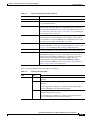
Features
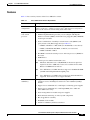
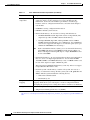
Table 1-1 lists some key features of the Cisco 7600 series routers.
Table 1-1
Cisco 7600 Series Routers Key Features
Feature
Description
Performance and
configuration
For detailed information about the features supported on Cisco 7600 series
routers, see the Cisco 7600 Series Router Cisco IOS Software Configuration
Guide for the version of software being used on the router.
Supervisor engine or
route switch
processor
•
Modular, upgradable feature modules for core switching logic
•
Modular Gigabit Ethernet ports that you can configure with Gigabit
Interface Converter (GBIC), small form-factor pluggable (SFP), XENPAK,
and X2 optics modules
•
Several combinations of multilayer switch feature cards (MSFCs) and
policy feature cards (PFCs) supported (see Table 2-1):
– MSFC4 and PFC3C or PFC3CXL (for the RSP720, see note below)
– MSFC3 and PFC3B, PFC3BXL, or PFC3A (see note below)
– MSFC2 and PFC or PFC2
Fault tolerance and
redundancy
•
The MSFC contains the switch processor and route processor (SP/RP) for
the router.
•
PCMCIA slot
•
Console port for terminal and modem access
Note
The Route Switch Processor 720 (RSP720) is the newest supervisor
engine for the Cisco 7600 series routers. It is available in Cisco IOS
Release 12.2SRB and later releases.
Note
Cisco IOS Release 12.2SRC introduces support for the RSP720-10GE
(an RSP with 10 Gigabit Ethernet uplink ports).
Note
Cisco IOS Release 12.2SXF is the last release in which the PFC3A is
supported. Later releases do not support this PFC.
•
Support for two hot-swappable (redundant) supervisor engines or route
switch processors, including fast switchover to the redundant (standby)
module
•
Support for two redundant AC- or DC-input, load-sharing power supplies
•
Support for two redundant AC- or DC-input PEMs (Cisco 7603 and
Cisco 7606 routers only)
•
Power management for modules and power supplies
•
Environmental monitoring of critical system components
•
Hot-swappable fan assembly
•
Redundant clock modules
•
LACP 1-1 redundancy with fast switchover
Cisco 7600 Series Router Supervisor Engine and Route Switch Processor Guide
OL-10100-04
1-3
Chapter 1
Cisco 7600 Product Overview
Cisco 7600 Series Routers
Table 1-1
Feature
Memory
components
Cisco 7600 Series Routers Key Features (continued)
Description
•
Electrically erasable programmable read-only memory (EEPROM) on the
supervisor engine or route switch processor stores module-specific
information, such as the serial number, part number, controller type,
hardware revision, configuration information, and other details unique to
each module.
•
NVRAM for storing configuration information.
•
DRAM for default system software.
•
Internal flash memory—To store the boot image. The defaults are:
Note
•
•
The RSP720 SP/RP and the Sup32 SP contain a CompactFlash (CF)
adapter that provides 512 MB of internal flash memory.
•
The Sup720 SP/RP, Sup32 RP, and Sup2 SP/RP contain 32-MB or
64-MB of internal flash memory. Cisco IOS Release 12.2(18)SXF and
later releases support the CF adapter as an orderable option (Cisco part
number CF-ADAPTER=) for these Sups. 1
In the command-line-interface (CLI), you access internal flash memory
as bootdisk (CF adapter) or bootflash (non-CF adatper). When you
install a CF adapter on the Sup720, Sup32, or Sup2, bootflash becomes
an alias to bootdisk.
External flash memory—To store and run software images and configuration
files or to serve as an input/output (I/O) device. You can install 64-MB,
128-MB, 256-MB, or 512-MB flash memory cards, or 1-GB MicroDrive card,
in slots on the supervisor engine or RSP front panel.
The Sup2 supports PCMCIA flash memory cards only. It does not support
CompactFlash or MicroDrive cards.
•
Flash file system—Flash memory contains a file system. You can use a
variety of commands to manage the file system (such as cd, pwd, dir, and
delete). The file system includes the following devices:
– Onboard bootflash/bootdisk
– Flash memory slot
Component hot
swapping
Management
All components (including optional redundant modules and fans) support hot
swapping, which allows you to add, replace, or remove components without
interrupting the system power or causing other software or interfaces to shut down.
•
CLI through the console port or Telnet
•
Simple Network Management Protocol (SNMP)
1. For information on how to install a CF adapter, see the instructions at:
http://www.cisco.com/en/US/products/hw/switches/ps708/products_installation_and_configuration_guide09186a0080537ae3.
html
Cisco 7600 Series Router Supervisor Engine and Route Switch Processor Guide
1-4
OL-10100-04
Chapter 1
Cisco 7600 Product Overview
Port Addresses
Port Addresses
Each port (or interface) in the Cisco 7600 series router has several different types of addresses. The
physical interface address is the actual physical location (slot and port) of the interface connector within
the chassis. The system software uses the physical addresses to control activity within the router and to
display status information. These physical slot and port addresses are not used by other devices in the
network; they are specific to the individual router and its internal components and software. For more
information, see the “Physical Interface Addresses” section on page 1-5.
The Media Access Control (MAC) address is a standardized data link layer address that is required for
every port or device that connects to a network. Other devices in the network use MAC addresses to
locate specific ports in the network and to create and update routing tables and data structures. Routers
use a unique method, described in the “MAC Addresses” section on page 1-6, to assign and control the
MAC addresses of their interfaces.
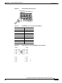
Physical Interface Addresses
Physical port addresses specify the actual physical location of each port on every module in the router,
as shown in Figure 1-1. The port address is a two-part number in the format slot/port number (for
example, 1/1, 1/2, 2/1, 2/2, and so on):
•
Slot—Identifies the slot in which the module is installed. Depending on the router layout, the slots
are numbered from top to bottom or right to left starting with 1 (1/n, 2/n, and so on).
– On horizontal-oriented chassis (such as the Cisco 7606 and Cisco 7613 routers), slots are
numbered from top to bottom.
– On vertical-oriented chassis (such as the Cisco 7609 router), slots are numbered from right to left.
•
Port number—Identifies the physical port number on the module. Port numbers always begin at 1
(n/1, n/2, and so on).
– On horizontal-oriented modules, ports are numbered from left to right.
– On vertical-oriented modules, ports are numbered from top to bottom.
Cisco 7600 Series Router Supervisor Engine and Route Switch Processor Guide
OL-10100-04
1-5
Chapter 1
Cisco 7600 Product Overview
Port Addresses
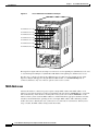
Figure 1-1
Cisco 7609 Router Port Address Examples
FAN
STATUS
AT
CO
E
R
PW
OL
E
PW
OL
NS
NS
EM
CO
ST
1
EM
SY
US
ST
WS-X6K-SUP2-2GE
ST
SY
US
R
MG
MT
SE
T
RE
MT
SE
MG
RE
T
CONSOLE
CONSOLE
NK 2
3
4
LI
NK
LI
NK 3
NK 3
LI
NK
LI 4
SE
NK
LI IER
M
RE
RR
CA AR
AL
RE
K
T
RR
CA AR
AL
LIN
T
SE
SE
T
RE
T
T
SE
SE
RE
RE
NK
LI IER
M
RR
CA AR
AL
NK
LI 4
NK 4
NK
NK
4 LI
4 LI
CONSOLE
PORT
MODE
LI
3
CONSOLE
PORT
MODE
3
4
3
NK
LI 3
NK
TI
R
IE
M
R
IE
M
AC
1
RR
CA AR
AL
RR
CA AR
AL
R
IE
M
1
TI
2
TX
RX
TX
RX
RX
1
TX
1
RT
RT
PO
PO
RX
RX
1
3
RT
3
PO
PCMCIA
PCMCIA
VE
TX
VE
TI
AC
AC
VE
RX
2
5
TI
5
AC
AC
VE
R
IE
RR M
CA AR K
AL LIN
TI
R
IE
M
AC
R
IE
M
RR
CA AR
AL
RR
CA AR
AL
R
IE
M
EJECT
TX
4
EJECT
TX
RR
CA AR
AL
4
TI
VE
VE
TX
RX
TX
RX
TX
RX
6
RX
6
PO
RX
7
2
TX
2
RT
RT
PO
PO
2
RX
RT
7
100%
Switch
TX
RX
TX
RX
Load
VE
Load
TI
TX
RX
VE
TI
AC
Switch
1%
100%
1%
AC
VE
SE
LE
CT
R
IE
M
TI
NE
XT
R
IE
RR M
CA AR
AL
AC
8
SE
LE
CT
RR
CA AR
AL
R
IE
M
8
NE
XT
TX
TX
RR
CA AR
AL
RX
PO
Port numbers 8/1 to 8/8
RX
K
PORT 1
LIN
K
TX
LIN
TX
RR
CA AR
AL
PORT 1
3
TX
3
RT
RT
PO
PO
3
RX
RT
TI
R
IE
RR M
CA AR
AL
AC
R
IE
RR M
CA AR K
AL LIN
R
IE
M
TI
AC
AC
VE
TI
VE
VE
TX
RX
TX
RX
TX
RX
Port numbers 9/1 to 9/8
RX
RX
RX
TX
TX
PORT 2
K
PORT 2
LIN
TX
55748
Port numbers 7/1 to 7/4
SUPERVISOR2
AT
LI
NK 2
3
4
LI
Port numbers 4/1 to 4/4
WS-X6K-SUP2-2GE
ST
SUPERVISOR2
NK 1
LI
3
4
Port numbers 3/1 to 3/4
OSM-40C12-POS-MM
2
LI
NK 1
NK
LI 2
NK
NK
Port numbers 2/1 to 2/2
US
AT
ST
3
LI
AC
TIV
E
2 LI
2 LI
4
1
1
AC
TIV
E
NK 1
1
2
LI
NK
ST
AT
US
OC12 POS MM
US
AT
ST
OSM-40C12-POS-MM
SWITCH FABRIC MDL
WS-C6500-SFM
1
2
LI
NK
ST
AT
US
OC12 POS MM
WS-C6500-SFM
1
2
LI
SWITCH FABRIC MDL
1
2
OSM-40C12-POS-MM
US
US
AT
ST
OC12 POS MM
AT
US
OSM-8OC3-POS MM
ST
AT
8 PORT OC3 POS MM
ST
OSM-8OC3-POS MM
8 PORT OC3 POS MM
Port numbers 1/1 to 1/2
o
o
INPUT
OK
FAN
OK
OUTPUT
FAIL
INPUT
OK
FAN
OK
OUTPUT
FAIL
The supervisor engine and route switch processor have two or more uplink ports (numbered n/1, n/2, and
so on). The Supervisor Engine 32 (WS-SUP32-GE-3B) has nine uplink ports, numbered n/1 to n/9.
In some cases, a single port supports two different types of connectors (for example, Port 2 on the
Supervisor Engine 720 supports a Gigabit Ethernet SFP module or a 10/100/1000-Mbps RJ-45
connector). However, only one of the two options can be active at a time.
MAC Addresses
All network interface connections (ports) require a unique MAC address. The MAC address of an
interface is stored in electrically erasable programmable read-only memory (EEPROM) on a component
that resides directly on the interface circuitry. The router system code reads the EEPROM for each
interface in the system, learns the MAC addresses, and then initializes appropriate hardware and data
structures. Each VLAN in the spanning tree has one unique MAC address. This addressing scheme
enables the router to identify the state (connected or not connected) of each interface. When you hot
swap a module, the MAC address changes with the module.
Cisco 7600 Series Router Supervisor Engine and Route Switch Processor Guide
1-6
OL-10100-04
CH A P T E R
2
Route Switch Processors and
Supervisor Engines
This chapter describes the route switch processors and supervisor engines supported on Cisco 7600
series routers and provides instructions for performing basic tasks on the modules. It contains the
following sections:
Note
•
Overview, page 2-2
•
Route Switch Processor 720, page 2-6
•
RSP720 with 10GE Uplink Ports, page 2-8
•
Supervisor Engine 720 and Supervisor Engine 32, page 2-12
•
Supervisor Engine 2, page 2-14
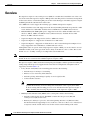
The route switch processor is the newest version of supervisor engine. See Table 2-1 for a list of the route
switch processor and supervisor engine configurations supported on Cisco 7600 series routers. Be sure
to review the release notes for the software version running on your router for information about any
restrictions and limitations that might apply.
Cisco 7600 Series Router Supervisor Engine and Route Switch Processor Guide
OL-10100-04
2-1
Chapter 2
Route Switch Processors and Supervisor Engines
Overview
Overview
The supervisor engine or route switch processor (RSP) is a module that is installed in one of the card
slots in the router. The supervisor engine or RSP provides switching and local and remote management
for the router and also contains the uplink ports for the router. Both types of modules (supervisor engine
and RSP) perform the same functions in the router.
Cisco 7600 series routers support the following types of RSPs and supervisor engines:
•
Route Switch Processor 720—Supported on all chassis (including enhanced) except the Cisco 7603
router and the Cisco OSR-7609. Available in Cisco IOS Release 12.2SRB and later releases.
•
RSP720-10GE (with 10GE uplink ports)—Supported on the Cisco 7604 and 7609 routers and
the Cisco 7603-S, 7606-S, and 7609-S routers (enhanced chassis). Available in Cisco IOS
Release 12.2SRC and later releases.
•
Supervisor Engine 720—Supported on all Cisco 7600 series routers.
•
Supervisor Engine 32—Supported on all but the Cisco 7603 router.
•
Supervisor Engine 2—Supported on all but the Cisco 7613 router. The Supervisor Engine 2 is no
longer supported in Cisco IOS Release 12.2SRA and later releases.
Although the router can operate with a single supervisor engine or RSP, you can also install a second
redundant module (of the same type) in the chassis. Only one module is active at a time. The second
module acts as a “standby,” serving as a backup if the active module fails.
Note
If the system does not include a redundant supervisor engine or RSP, you can install another type of
module in the slot reserved for the redundant supervisor engine or RSP.
The supervisor engine or RSP contains the following integrated daughter cards that perform forwarding and
routing and provide the protocols supported on the router. Several configurations of daughter cards are
supported (as shown in Table 2-1).
•
Policy Feature Card (PFC) is the forwarding plane and does the following:
– Performs Layer 2 and Layer 3 forwarding.
– Enforces access control list (ACL) functions.
– Performs policing and marking for quality of service (QoS) traffic.
– Collects Netflow statistics.
Note
•
A high-capacity (XL) PFC is also available. The XL version (PFC3BXL or PFC3CXL)
provides more memory for more routing table and netflow cache capacity than a PFC.
It allows routing and forwarding processes to be offloaded from the supervisor engine or
RSP to the PFC, thus increasing the performance of the supervisor engine or RSP.
Multilayer Switch Feature Card (MSFC) is the control plane and does the following:
– Performs routing for the chassis. The MSFC contains the route processor (RP) and
switch processor (SP) for the router.
– Runs Layer 2 and Layer 3 protocols, such as the Spanning Tree Protocol (STP) and others.
For information about supported protocols, see the Cisco 7600 Series Router Cisco IOS Software
Configuration Guide and the release notes for the software version running on the router.
Cisco 7600 Series Router Supervisor Engine and Route Switch Processor Guide
2-2
OL-10100-04
Chapter 2
Route Switch Processors and Supervisor Engines
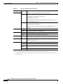
Overview
Table 2-1 lists the RSP and supervisor engine configurations supported on Cisco 7600 series routers.
Specific combinations of processors and modules may not be supported in your chassis. See the release
notes for your software version for information about supported combinations.
Table 2-1
Route Switch Processor and Supervisor Engine Configurations
Product Number
Description
Route Switch Processor 720
RSP720-3C-10GE
•
Two 10 Gigabit Ethernet (10GE) uplink ports support 10-Gbps X2
modules
•
Three Gigabit Ethernet (1GE) uplink ports: two ports support
1-Gbps small form-factor pluggable (SFP) module; one port
supports 10/100/1000-Mbps RJ-45 connector
Note
Use Category 5 Shielded Twisted Pair cable at the port that
supports the10/100/1000-Mbps RJ-45 connector.
•
Integrated 720-Gbps switch fabric
•
PFC3C and MSFC4 with 512-MB bootflash, 4-MB NVRAM,
4-MB ROMmon, and several DRAM options:
– Route processor (RP): 1- to 4-GB DRAM (default 1 GB)
– Switch processor (SP): 1- to 2-GB DRAM (default 1 GB)
RSP720-3CXL-10GE
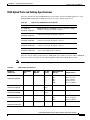
•
One CompactFlash Type II slot (512 KB) on front panel and two
internal CompactFlash (512 KB each for RP and SP; you can
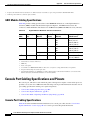
optionally increase each internal CompactFlash to 1 GB)
•
Requires larger power supplies and a high-speed fan tray
•
QoS port architecture, 10GE ports (Rx/Tx): 8q8t/1p7q8t (CoS)
•
QoS port architecture, 1GE ports (Rx/Tx): 2q8t/1p3q8t
•
Two 10GE) uplink ports support 10-Gbps X2 modules
•
Three 1GE)uplink ports: two ports support 1-Gbps small
form-factor pluggable (SFP) module; one port supports
10/100/1000-Mbps RJ-45 connector
Note
Use Category 5 Shielded Twisted Pair cable at the port that
supports the10/100/1000-Mbps RJ-45 connector.
•
Integrated 720-Gbps switch fabric
•
PFC3CXL (high-capacity) and MSFC4 with 512-MB bootflash,
4-MB NVRAM, 4-MB ROMmon, and several DRAM options:
– Route processor (RP): 1- to 4-GB DRAM (default 2 GB)
– Switch processor (SP): 1- to 2-GB DRAM (default 1 GB)
•
One CompactFlash Type II slot (512 KB) on front panel and two
internal CompactFlash (512 KB each for RP and SP; you can
optionally increase each internal CompactFlash to 1 GB)
•
Requires larger power supplies and a high-speed fan tray
•
QoS port architecture, 10GE ports (Rx/Tx): 8q8t/1p7q8t (CoS)
•
QoS port architecture, 1GE ports (Rx/Tx): 2q8t/1p3q8t
Cisco 7600 Series Router Supervisor Engine and Route Switch Processor Guide
OL-10100-04
2-3
Chapter 2
Route Switch Processors and Supervisor Engines
Overview
Table 2-1
Route Switch Processor and Supervisor Engine Configurations (continued)
Product Number
Note
Description
See the “QoS on the RSP720-10GE” section on page 2-10 for more information about the
QoS port architecture on the uplink ports.
RSP720-3C-GE
•
Two Gigabit Ethernet uplink ports: port 1 supports a 1-Gbps SFP
module; port 2 is configurable with either a 1-Gbps SFP module
or a 10/100/1000-Mbps RJ-45 connector
•
Integrated 720-Gbps switch fabric
•
PFC3C and MSFC4 with 512-MB bootflash, 4-MB NVRAM,
4-MB ROMmon, and several DRAM options:
– RP: 1- to 4-GB DRAM (default 1 GB)
– SP: 1- to 2-GB DRAM (default 1 GB)
RSP720-3CXL-GE
•
Two CompactFlash Type II slots on front panel (512 KB default)
and two internal CompactFlash slots (one each for RP and SP,
512 KB default for each)
•
Requires larger power supplies and a high-speed fan tray
•
QoS port architecture (Rx/Tx): 1p1q4t/1p2q2t
•
Two Gigabit Ethernet uplink ports: port 1 supports a 1-Gbps SFP
module; port 2 is configurable with either a 1-Gbps SFP module
or a 10/100/1000-Mbps RJ-45 connector
•
Integrated 720-Gbps switch fabric
•
PFC3CXL (high-capacity) and MSFC4 with 512-MB bootflash,
4-MB NVRAM, 4-MB ROMmon, and several DRAM options:
– Route processor (RP): 1- to 4-GB DRAM (default 2 GB)
– Switch processor (SP): 1- to 2-GB DRAM (default 1 GB)
•
Two CompactFlash Type II slots on front panel (512 KB default)
and two internal CompactFlash slots (one each for RP and SP,
512 KB default for each)
•
Requires larger power supplies and a high-speed fan tray
•
QoS port architecture (Rx/Tx): 1p1q4t/1p2q2t
•
Two Gigabit Ethernet uplink ports: port 1 supports a 1-Gbps SFP
module; port 2 is configurable with either a 1-Gbps SFP module
or a 10/100/1000-Mbps RJ-45 connector
•
Integrated 720-Gbps switch fabric
•
PFC3A and MSFC3 with 2-MB NVRAM, 512-MB DRAM, and
64-MB bootflash (see note below)
•
Two CompactFlash Type II slots
•
Requires larger power supplies and a high-speed fan tray
•
QoS port architecture (Rx/Tx): 1p1q4t/1p2q2t
Supervisor Engine 720
WS-SUP720
Note
Cisco IOS Release 12.2SXF is the last release in which the
Sup720 with PFC3A is supported.
Cisco 7600 Series Router Supervisor Engine and Route Switch Processor Guide
2-4
OL-10100-04
Chapter 2
Route Switch Processors and Supervisor Engines
Overview
Table 2-1
Route Switch Processor and Supervisor Engine Configurations (continued)
Product Number
WS-SUP720-3B
WS-SUP720-3BXL
Note
Description
•
Two Gigabit Ethernet uplink ports: port 1 supports a 1-Gbps SFP
module; port 2 is configurable with either a 1-Gbps SFP module
or a 10/100/1000-Mbps RJ-45 connector
•
Integrated 720-Gbps switch fabric
•
PFC3B and MSFC3 with 2-MB NVRAM, 512-MB DRAM, and
64-MB bootflash (see note below)
•
Two CompactFlash Type II slots
•
Requires larger power supplies and a high-speed fan tray
•
QoS port architecture (Rx/Tx): 1p1q4t/1p2q2t
•
Two Ethernet uplink ports: port 1 supports a 1-Gbps SFP
module; port 2 is configurable with either a 1-Gbps SFP module
or a 10/100/1000-Mbps RJ-45 connector
•
Integrated 720-Gbps switch fabric
•
PFC3BXL and MSFC3 with 2-MB NVRAM, 1-GB DRAM, and
64-MB bootflash; high-capacity PFC3BXL allows routing and
forwarding processes to be offloaded from the supervisor engine
to the PFC (see note below)
•
Two CompactFlash Type II slots
•
Requires larger power supplies and a high-speed fan tray
•
QoS port architecture (Rx/Tx): 1p1q4t/1p2q2t
A CompactFlash (CF) adapter with 512-MB bootflash is available for Sup720 modules in
Release 12.2(18)SXF and later releases. Use the Cisco part number CF-ADAPTER= for
ordering.
Supervisor Engine 32
WS-SUP32-GE-3B
WS-SUP32-10GE-3B
•
Nine Gigabit Ethernet uplink ports: eight SFP modules and one
RJ-45 10/100/1000-Mbps connector
•
Integrated 32-Gbps switch fabric
•
PFC3B and MSFC2 daughter cards (see notes below)
•
QoS port architecture (Rx/Tx): 1p3q8t/1p3q8t
•
Two 10-Gigabit Ethernet ports (XENPAKs) and one
10/100/1000-Mbps connector
•
Integrated 32-Gbps switch fabric
•
PFC3B and MSFC2 daughter cards (see notes below)
•
QoS port architecture (Rx/Tx): 1p3q8t/1p3q8t
Note
To run Release 12.2SRB, the Sup32 requires a minimum of 512-MB DRAM.
Note
A CF adapter with 512-MB bootflash is available for Sup32 modules in Release 12.2(18)SXF
and later releases. Use the Cisco part number CF-ADAPTER= for ordering.
Supervisor Engine 2
Cisco 7600 Series Router Supervisor Engine and Route Switch Processor Guide
OL-10100-04
2-5
Chapter 2
Route Switch Processors and Supervisor Engines
Route Switch Processor 720
Table 2-1
Route Switch Processor and Supervisor Engine Configurations (continued)
Product Number
WS-X6K-S2-MSFC2
WS-X6K-S2U-MSFC2
WS-X6K-S2-PFC2
WS-X6500-SFM2
Note
Description
•
Two dual-port 1000BASE-X GBIC uplinks, 16-MB bootflash,
128-MB DRAM on supervisor engine and 128 MB on MSFC2
•
PFC2 and MSFC2
•
Fabric enabled to support optional switch fabric module (SFM2)
•
QoS port architecture (Rx/Tx): 1p1q4t/1p2q2t
•
Two dual-port 1000BASE-X GBIC uplinks, 32-MB bootflash,
256-MB DRAM on supervisor engine and 256 MB on MSFC2
•
PFC2 and MSFC2
•
Fabric enabled to support optional SFM2
•
QoS port architecture (Rx/Tx): 1p1q4t/1p2q2t
•
Two dual-port 1000BASE-X GBIC uplinks
•
PFC2; fabric enabled, supports optional SFM2
•
QoS port architecture (Rx/Tx): 1p1q4t/1p2q2t
•
(Optional) SFM2
The Sup2 is not supported in Cisco IOS Release 12.2SRA and later releases.
Route Switch Processor 720
This section describes the Route Switch Processor 720 (RSP720). The Cisco 7600 RSP720 consists of a
full-size board and two integrated daughter cards: the MSFC4 and a PFC3C or PFC3CXL. The RSP720
has an integrated switch fabric that interconnects all of the line cards in the Cisco 7600 router with
point-to-point 20-Gbps full-duplex serial channels.
Note
•
Cisco IOS Release 12.2SRB and later releases support the RSP720; earlier releases do not.
The RSP720 is supported on all Cisco 7600 routers (including enhanced chassis) except the Cisco
7603 and the Cisco OSR-7609.
•
Cisco IOS Release 12.2SRC and later releases support an RSP720 that has 10GE uplinks
(RSP720-3C-10GE and RSP720-3CXL-10GE). See the “RSP720 with 10GE Uplink Ports” section
on page 2-8 for more information.
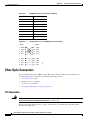
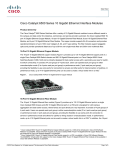
Figure 2-1 shows the RSP720-3C-GE front panel, which is the same as the RSP720-3CXL-GE front
panel. See Table 2-2 and Table 2-3 for information about the front-panel controls and LEDs.
Cisco 7600 Series Router Supervisor Engine and Route Switch Processor Guide
2-6
OL-10100-04
Chapter 2
Route Switch Processors and Supervisor Engines
Route Switch Processor 720
Figure 2-1
Route Switch Processor 720 (RSP720-3C-GE) Front Panel
STATUS LEDs
CompactFlash
Type II slots
LINK LEDs
191402
RSP720-3C-GE
RSP 720 WITH INTEGRATED SWITCH FABRIC/3C-GE
Disk LEDs
Gigabit Ethernet
uplink port
CONSOLE port
10/100/1000 uplink port
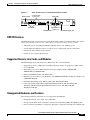
RSP720 Features
The RSP720 provides several new features and enhancements, which are summarized here. For details,
see the Cisco 7600 Series Router Cisco IOS Software Configuration Guide, Release 12.2SR.
•
720 gigabits per second (Gbps) bandwidth (320 Gbps ingress and 320 Gbps egress)
•
A faster CPU and additional memory to support larger configurations and more subscribers
•
Performance and scalability improvements
•
Quality of service (QoS) enhancements
Supported Chassis, Line Cards, and Modules
The RSP720 supports the following Cisco 7600 chassis, line cards and modules:
•
Supported on all Cisco 7600 routers (including enhanced chassis) except the Cisco 7603 and the
Cisco OSR-7609
•
SPA interface processors (SIPs) and their shared port adapters (SPAs): 7600-SIP-600,
7600-SIP-400, and 7600-SIP-200
•
Enhanced FlexWAN module (WS-X6582-2PA)
•
Ethernet services modules: 2-port 10 GE line card (7600-ESM-2X10GE) and 20-port 1 GE line card
(7600-ESM-20X1GE)
•
Distributed Forwarding Cards: DFC3C, DFC3CXL, DFC3B, DFC3BXL
•
LAN cards (which require DFC): WS-X6704-10GE, WS-X6724-SFP, WS-X6748-SFP,
WS-X6748-GE-TX, WS-X6708A-10GE, WS-X67xxA series, WS-X6148-FE-SFP,
WS-X6148A-GE-TX
Unsupported Hardware and Features
The following hardware and features are not supported by the RSP720:
•
Unsupported chassis: Cisco 7603, Cisco OSR-7609.
•
Unsupported modules: Services modules, Optical Service Modules (OSMs), FlexWAN module.
•
Server load balancing (SLB) is not supported, although it is supported on the Supervisor Engine 720.
Cisco 7600 Series Router Supervisor Engine and Route Switch Processor Guide
OL-10100-04
2-7
Chapter 2
Route Switch Processors and Supervisor Engines
RSP720 with 10GE Uplink Ports
RSP720 with 10GE Uplink Ports
Cisco IOS Release 12.2SRC introduces a new RSP720 with 10 Gigabit Ethernet (GE) uplink ports
(RSP720-10GE). The Cisco 7600 RSP720-10GE consists of a full-size board and two integrated
daughter cards: an MSFC4 and a PFC. The RSP720-10GE has an integrated switch fabric that
interconnects all of the line cards in the router with point-to-point 20-Gbps full-duplex serial channels.
Two versions of the RSP720-10GE module are available:
•
RSP720-3C-10GE
•
RSP720-3CXL-10GE
Because of physical differences between the RSP720 and RSP720-10GE (such as the CPU memory map
and ASIC operation), there are several configuration guidelines and restrictions you should be aware of.
See the “RSP720-10GE Usage Guidelines and Limitations” section on page 2-10 for details.
Following are the total power requirements for the RSP720-10GE:
•
RSP720-3C-10GE = 355 watts (total power)
•
RSP720-3CXL-10GE = 378 watts (total power)
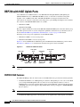
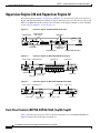
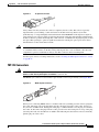
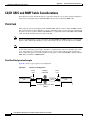
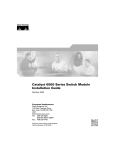
Figure 2-2 shows the RSP720-3C-10GE front panel. The RSP720-3CXL-10GE front panel is similar.
See Table 2-2 and Table 2-3 for information about the front-panel controls and LEDs.
Figure 2-2
RSP720-3C-10GE Front Panel
1-GE uplink
ports
Disk LEDs
CONSOLE
port
10-GE uplink
ports
RSP720-3C-10GE
DISK 0
1
SFP
4
10/100/100
3
5
3
STATUS SYSTEM ACTIVE PWR MGMT
RESET
RSP720 WITH INTERATED SWITCH FABRIC/PFC3C-10GE
CONSOLE
LINK
STATUS
LEDs
Note
CompactFlash
Type II slots
LINK
LINK
LEDs
LINK
LINK
LINK
10/100/1000
uplink port
250253
10GE UPLINK
UPLINK
EJECT
LINK
LEDs
Use Category 5 Shielded Twisted Pair cable at the port that supports the10/100/1000-Mbps RJ-45
connector.
RSP720-10GE Features
The RSP720-10GE provides all of the features of the RSP720 and also provides the following benefits:
•
Note
The RSP720-10GE has two 10GE uplink ports and three 1GE uplink ports. You can use the 10GE
ports as high-bandwidth uplinks and save chassis slots for high-density interfaces, such as a
SIP/SPA. This is especially useful in smaller chassis and in redundant configurations. For the three
1GE uplink ports, two ports support 1-Gbps SFP modules and one port supports a 10/100/1000-Mbps
RJ-45 connector.
Use CAT5 Shielded Twisted Pair cable at the port that supports the10/100/1000-Mbps RJ-45 connector.
•
The RSP720-10GE supports the following line rates for uplink traffic and backplane forwarding:
Cisco 7600 Series Router Supervisor Engine and Route Switch Processor Guide
2-8
OL-10100-04
Chapter 2
Route Switch Processors and Supervisor Engines
RSP720 with 10GE Uplink Ports
– 10 gigabits per second (Gbps) on both 10GE ports
– 1 Gbps on all three 1GE ports
– 16 Gbps backplane forwarding
When all five uplink ports are operational, the total bandwidth for uplink traffic is 20 Gbps (20 GE).
•
The RSP720-10GE provides flexible memory options like the RSP720. The RSP720-10GE ships
with 2-GB memory on the route processor (RP) and 1-GB memory on the switch processor (SP).
Memory options are available to upgrade to 4-GB memory on the RP and 2-GB memory on the SP.
•
The RSP720-10GE supports Route Processor Redundancy (RPR) mode. However, uplink ports on
the standby supervisor will be unusable.
See the “RSP720-10GE Usage Guidelines and Limitations” section on page 2-10 for information about
things to consider when you use the RSP720-10GE.
Supported Chassis, Line Cards, and Modules
The RSP720-10GE supports the following chassis and modules:
•
Supported on the Cisco 7604 and 7609 chassis and the Cisco 7603-S, 7606-S, and 7609-S chassis
Note
If you insert an RSP720-10GE into an unsupported chassis, the RSP720-10GE drops to
ROMmon and only the console is accessible.
•
SPA interface processors (SIPs) and their shared port adapters (SPAs): 7600-SIP-600,
7600-SIP-400, and 7600-SIP-200
•
Enhanced FlexWAN module (WS-X6582-2PA)
•
Ethernet services modules: 2-port 10 GE line card (7600-ESM-2X10GE) and 20-port 1 GE line card
(7600-ESM-20X1GE)
•
Distributed Forwarding Cards: DFC3C, DFC3CXL, DFC3B, DFC3BXL
•
LAN cards (which require CFC or DFC): WS-X6704-10GE, WS-X6724-SFP, WS-X6748-SFP,
WS-X6748-GE-TX, WS-X6708A-10GE, WS-X67xxA series, WS-X6148-FE-SFP,
WS-X6148A-GE-TX
•
Uplink port transceiver modules: see Appendix B, “Cable and Connector Specifications”
Note
The RSP720-10GE also supports two new 8-port 10GE line cards (WS-X6708-10G-3C and
WS-X6708-10G-3CXL). The line cards, which provide 2-to-1 oversubscription, are
available in Cisco IOS Release 12.2SRC and later.
Unsupported Chassis and Modules
The RSP720-10GE does not support the following chassis and modules:
•
Unsupported chassis: Cisco 7603, 7606, and 7613 chassis
•
Unsupported modules: Services modules, Optical Service Modules (OSMs), FlexWAN module
Unsupported Features
In Cisco IOS Release 12.2SRC, the RSP720-10GE does not support the following features, which are
supported on the RSP720:
Cisco 7600 Series Router Supervisor Engine and Route Switch Processor Guide
OL-10100-04
2-9
Chapter 2
Route Switch Processors and Supervisor Engines
RSP720 with 10GE Uplink Ports
•
High-availability features such as NonStop Forwarding with Stateful Switchover (NSF/SSO) and
In-Service Software Upgrade (ISSU) are not supported. Only Route Processor Redundancy (RPR)
mode is supported.
•
The uplinks on the standby RSP720-10GE are not active. This restriction exists because the uplink
ports must perform lookups on the active RSP, which is not possible in RPR mode.
•
Intelligent Service Gateway is not supported.
•
Device authentication to prevent counterfeiting
•
Keystore controller for key authentication
•
Virtual switch functionality
RSP720-10GE Usage Guidelines and Limitations
Observe the following guidelines when using the RSP720-10GE:
•
The RSP720-10GE runs the same Cisco IOS software images as the RSP720. The following
software image feature sets are available for the RSP720-10GE: ipservices, ipservicesk9,
advipservices, advipservicesk9, and adventerprisek9.
•
Line cards require new firmware to operate with the RSP720-10GE. If a line card does not have the
correct firmware, an error message is displayed on boot-up and the line card is powered off.
•
The RSP720-10GE uses new ROMMON software for both the SP and RP. Because the
RSP720-10GE and RSP720 use a different IO memory map, the RSPs cannot share the same
ROMMON software.
– If you attempt to load RSP720 ROMMON software onto the RSP720-10GE, the RSP720-10GE
does not power up and the ROMMON banner is not displayed.
– If you load RSP720-10GE ROMMON software onto the RSP720, Cisco IOS software boots up
but the software detects a mismatch and enters ROMMON mode.
•
You can configure the RSP720-10GE to run QoS features on all uplink ports (10GE and 1GE) or on
10GE ports only. A new CLI command (mls qos supervisor 10g-only) is available to configure the
module to run QoS features on 10GE ports only. QoS operates differently in each mode. See the
“QoS on the RSP720-10GE” section on page 2-10 for more information.
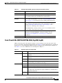
QoS on the RSP720-10GE
The RSP720-10GE has both 10GE and 1GE uplink ports. You can configure the RSP720-10GE to run
QoS features on all uplink ports (mixed mode) or on 10GE ports only. The number of queues available
for QoS depends on which mode is used:
•
In mixed mode (10GE and 1GE ports), the default, only four queues are available for QoS.
The QoS port architecture for 1GE ports is (Rx/Tx): 2q8t/1p3q8t.
Cisco 7600 Series Router Supervisor Engine and Route Switch Processor Guide
2-10
OL-10100-04
Chapter 2
Route Switch Processors and Supervisor Engines
RSP720 with 10GE Uplink Ports
•
In 10GE only mode, eight queues are available for QoS. Use the mls qos supervisor 10g-only
command to enable 10GE only mode.
The QoS port architecture for 10GE only mode is as follows (Rx/Tx):
– 8q8t/1p7q8t (CoS)
– 16q8t/1p15q8t (DSCP)
– 16q1t/1p15q1t (VLAN)
QoS Configuration Guidelines
As you configure QoS on the RSP720-10GE, consider the following:
•
When you switch between mixed-mode QoS and 10GE only mode, any existing QoS configuration
on the uplinks is lost. You must reconfigure QoS.
•
While transitioning between modes, service will be temporarily lost on the uplinks.
•
You can manually shut down all three 1GE ports before issuing the mls qos supervisor 10g-only
command to switch to 10GE only mode. If you do not shut down the ports first, the mls qos
supervisor 10g-only command shuts down the ports.
•
When you switch from 10GE10GE only to mixed-mode QoS, you must issue the no shutdown
command on each of the three 1GE ports to resume QoS service on those ports.
•
In 10GE only mode, the 1GE ports are visible but they remain in an administratively down state.
Configuring 10GE Only QoS
Cisco IOS Release 12.2SRC introduces a new command to enable QoS features on 10GE uplink ports
only. By default, the router runs in mixed mode, which means that QoS is enabled on both the 10GE
uplink ports and the 1GE uplink ports.
mls qos supervisor 10g-only
no mls qos supervisor 10g-only
Note
You can shut down all three 1GE uplink ports before entering the mls qos supervisor 10g-only
command. If you do not shut down the ports first, the mls qos supervisor 10g-only command shuts down
the ports.
Cisco 7600 Series Router Supervisor Engine and Route Switch Processor Guide
OL-10100-04
2-11
Chapter 2
Route Switch Processors and Supervisor Engines
Supervisor Engine 720 and Supervisor Engine 32
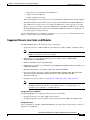
Supervisor Engine 720 and Supervisor Engine 32
The following figures (Figure 2-3, Figure 2-4, and Figure 2-5) show the front panel on the Supervisor
Engine 720 (Sup720) and Supervisor Engine 32 (Sup32). The tables that follow describe the controls and
LEDs on the RSP720, Sup720, and Sup32. For information on the Supervisor Engine 2 controls and LEDs,
see the “Supervisor Engine 2” section on page 2-14.
Figure 2-3
Supervisor Engine 720 (WS-SUP720) Front Panel
CompactFlash
Type II slots
LINK LEDs
87890
STATUS LEDs
Disk LEDs
Figure 2-4
Gigabit Ethernet
uplink port
CONSOLE port
10/100/1000 uplink port
Supervisor Engine 32 (WS-SUP32-GE-3B) Front Panel
Uplink ports
Uplink port
120690
Status LEDs CONSOLE port
RESET button
Disk LED
Figure 2-5
CompactFlash
Type II slot
Link Status LEDs
USB ports
Supervisor Engine 32 (WS-SUP32-10GE-3B) Front Panel
Uplink ports
Uplink port
120691
Status LEDs CONSOLE port
Disk LED
CompactFlash
Type II slot
Link Status LEDs
USB ports
Front-Panel Controls (RSP720, RSP720-10GE, Sup720, Sup32)
Table 2-2 describes the front-panel controls on the Route Switch Processor 720 and RSP720-10GE, the
Supervisor Engine 720, and the Supervisor Engine 32.
Cisco 7600 Series Router Supervisor Engine and Route Switch Processor Guide
2-12
OL-10100-04
Chapter 2
Route Switch Processors and Supervisor Engines
Supervisor Engine 720 and Supervisor Engine 32
Table 2-2
RSP720, RSP720-10GE, Sup720, and Sup32 Front-Panel Controls
Component
Description
Status LEDs
Indicate the status of various functions on the module (see Table 2-3).
Reset Button
Restarts the router. Use a ballpoint pen tip or other small, pointed object to
access the Reset button. Not all modules have a Reset button.
CompactFlash
Disk Slots
One or two slots for flash memory cards. Do not remove the card from
the slot while the disk LED is on. See the “Using Flash Memory Cards”
section on page 3-12 for information about working with flash memory.
Console Port
Provides access to the router. The port is an EIA/TIA-232 asynchronous,
serial connection with hardware flow control and an RJ-45 connector.
See the “Connecting to the Console Port” section on page 3-9 for
instructions on connecting to the console port.
On the RSP720, the console port allows you to access either the switch
processor (SP) or the route processor (RP).
Uplink Ports
Used to connect the router to other network devices. The uplink ports are
configurable with SFP, XENPAK, or X2 optics modules. See the
“Connecting to the Uplink Ports” section on page 3-10 for more
information.
USB Ports (Sup32 only)
Each USB port can function as a console port or security key.
Front-Panel LEDs (RSP720, RSP720-10GE, Sup720, Sup32)
LEDs on the front panel of the supervisor engine or route switch processor show the status of the
processor and other components installed in the router. Table 2-3 lists the LED functions on the Route
Switch Processor 720 and RSP720-10GE, the Supervisor Engine 720, and the Supervisor Engine 32.
See Table 2-5 for a list of LED functions on the Supervisor Engine 2.
Table 2-3
RSP720, Sup720, and Sup32 LEDs
LED
Color
Description
STATUS
Green
All diagnostics pass; the module is operational (normal initialization
sequence).
Orange
The module is booting or running diagnostics (normal initialization
sequence).
Yellow
Minor hardware problems.
Red
An overtemperature condition occurred. (A major threshold has been
exceeded during environmental monitoring.)
Green
All chassis environmental monitors are reporting OK.
Orange
The module is powering up or a minor hardware fault has occurred.
Red
Major hardware problem.
SYSTEM1
The temperature of the supervisor engine or RSP has exceeded the major
temperature threshold.
Blinking
Red
Continuous backplane stall.
Cisco 7600 Series Router Supervisor Engine and Route Switch Processor Guide
OL-10100-04
2-13
Chapter 2
Route Switch Processors and Supervisor Engines
Supervisor Engine 2
Table 2-3
RSP720, Sup720, and Sup32 LEDs (continued)
LED
Color
Description
ACTIVE
Green
The supervisor engine or RSP is operational and active.
Orange
The supervisor engine or RSP is powering up or is in standby mode.
Green
Sufficient power is available for all modules installed in the router.
Orange
The supervisor engine or RSP is powering up or has minor hardware
problems.
Red
Major hardware problem.
DISK
Green
The disk is active. Do not remove the disk while the light is on or the file
may be corrupted.
LINK
Green
The port is operational.
Orange
The port is disabled.
Flashing
orange
The port is bad.
Off
The supervisor engine or RSP is powering up or the port is enabled and
there is no link.
1
PWR MGMT
1. The SYSTEM and PWR MGMT LEDs on a redundant supervisor engine or RSP are synchronized to the active module.
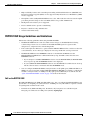
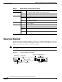
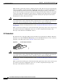
Supervisor Engine 2
This section describes the Supervisor Engine 2 (see Figure 2-6), which has slightly different controls and
features than the Supervisor Engine 720 and Supervisor Engine 32. Table 2-4 describes the controls and
features on the front panel and Table 2-5 describes the LEDs.
Note
In Cisco IOS Release 12.2SR and later releases, the Supervisor Engine 2 is no longer supported on
Cisco 7600 series routers.
Figure 2-6
Supervisor Engine 2 Front Panel
CONSOLE port
Switch load 1000BASE-X GBIC
display
Uplink Ports
PCMCIA LED
WS-X6K-SUP2-2GE
PCMCIA
EJECT
LIN
K
SUPERVISOR2
Status
LEDs
PORT 2
1%
CONSOLE PORT
PCMCIA slot
MODE switch
LIN
K
LE
CONSOLE
44312
ES
ET
M
G
PORT 1
R
S
EM
U
SO
R
N
ST
PW
AT
O
C
SY
ST
Load
M
T
Switch
100%
CONSOLE
PORT
MODE
LINK LEDs
RESET button
Cisco 7600 Series Router Supervisor Engine and Route Switch Processor Guide
2-14
OL-10100-04
Chapter 2
Route Switch Processors and Supervisor Engines
Supervisor Engine 2
Table 2-4
Supervisor Engine 2 Front-Panel Controls
Component
Description
Status LEDs
Indicate the status of various functions on the module (see Table 2-5).
Reset Button
Restarts the router. Use a ballpoint pen tip or other small, pointed object
to access the Reset button.
Console Port
Provides access to the router either locally (with a console terminal) or
remotely (with a modem). The port is an EIA/TIA-232 asynchronous,
serial connection with hardware flow control and an RJ-45 connector. See
the “Connecting to the Console Port” section on page 3-9 for instructions
on connecting to the console port.
Console Port Mode Switch
Enables you to connect a terminal to the console port using either the
cable and adapters provided with the router (switch in the in position,
factory default) or a Catalyst 5000 Supervisor Engine III console cable
and adapter, not provided (switch in the out position).
PCMCIA Slot and LED
PCMCIA flash memory card slot. Do not remove the card from the slot
while the disk LED is on. See the “Using Flash Memory Cards” section
on page 3-12 for information about working with flash memory.
Switch Load Meter
A visual approximation of the current traffic load across the backplane.
Uplink Ports
Used to connect the router to another network device. Two dual-port
Gigabit Ethernet uplink ports operate in full-duplex mode only. You can
configure the ports with any combination of copper, short-wave (SX),
long-wave/long-haul (LX/LH), extended-reach (ZX), and coarse
wavelength division multiplexing (CWDM) 1000BASE-X Gigabit
Interface Converters (GBICs). See the “Connecting to the Uplink Ports”
section on page 3-10 for more information.
Table 2-5 lists the LED functions on the Supervisor Engine 2.
Table 2-5
Supervisor Engine 2 LEDs
LED
Color
Description
STATUS
Green
All diagnostics pass; the module is operational (normal initialization
sequence).
Orange
The module is booting or running diagnostics (normal initialization
sequence).
An overtemperature condition has occurred. (A minor threshold has
been exceeded during environmental monitoring.)
Red
Diagnostic test failed; the module is not operational. (The fault occurred
during the initialization sequence.)
An overtemperature condition has occurred. (A major threshold has
been exceeded during environmental monitoring.)
Cisco 7600 Series Router Supervisor Engine and Route Switch Processor Guide
OL-10100-04
2-15
Chapter 2
Route Switch Processors and Supervisor Engines
Supervisor Engine 2
Table 2-5
Supervisor Engine 2 LEDs (continued)
LED
1
SYSTEM
Color
Description
Green
All chassis environmental monitors are reporting OK.
Orange
The power supply or power supply fan failed.
Incompatible power supplies are installed.
The redundant clock failed.
One VTT2 module has failed or the VTT module temperature minor
threshold has been exceeded.3
Red
Two VTT modules failed or the VTT module temperature major
threshold has been exceeded.3
The temperature of the supervisor engine major threshold has been
exceeded.
CONSOLE
Green
The supervisor engine is operational and active.
Orange
The supervisor engine is in standby mode.
Green
Sufficient power is available for all modules.
Orange
Sufficient power is not available for all modules.
SWITCH LOAD
-
If the system is operational, the switch load meter indicates (as an
approximate percentage) the current traffic load over the backplane.
PCMCIA
-
The PCMCIA LED is lit when no PCMCIA card is in the slot and goes
off when you insert a card.
LINK
Green
The port is operational.
Orange
The link has been disabled by software.
Flashing
orange
The link is bad and has been disabled due to a hardware failure.
Off
No signal is detected.
1
PWR MGMT
1. The SYSTEM and PWR MGMT LED indications on a redundant supervisor engine are synchronized to the active engine.
2. VTT = voltage termination. The VTT module terminates signals on the system switching bus.
3. If no redundant supervisor engine is installed and there is a VTT module minor or major overtemperature condition, the
system shuts down.
Cisco 7600 Series Router Supervisor Engine and Route Switch Processor Guide
2-16
OL-10100-04
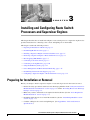
CH A P T E R
3
Installing and Configuring Route Switch
Processors and Supervisor Engines
This chapter describes how to install and configure a route switch processor or supervisor engine. It also
provides instructions for connecting to the console and uplink ports on the module.
This chapter contains the following sections:
•
Preparing for Installation or Removal, page 3-1
•
Determining Module Location, page 3-3
•
Installing a Supervisor Engine or Route Switch Processor, page 3-4
•
Removing a Supervisor Engine or Route Switch Processor, page 3-7
•
Hot Swapping (OIR) Modules, page 3-8
•
Connecting to the Console Port, page 3-9
•
Connecting to the Uplink Ports, page 3-10
•
Using Flash Memory Cards, page 3-12
•
Power Management and Environmental Monitoring, page 3-14
•
Determining Software Feature Support, page 3-14
•
Configuring a Supervisor Engine or Route Switch Processor, page 3-14
Preparing for Installation or Removal
Before you attempt to install a supervisor engine or route switch processor in the router, be sure to:
•
Review the safety precautions and electrostatic discharge guidelines in the “Safety Precautions for
Module Installation and Removal” section on page 3-2 and the “Preventing Electrostatic Discharge
Damage” section on page 3-2.
•
Make sure you have on hand the tools required for the installation. (See the “Tools Required for
Module Installation” section on page 3-3.)
•
Determine which chassis slot to install the module in. (See the “Determining Module Location”
section on page 3-3.)
•
Consider cabling for the console and uplink ports. (See Appendix B, “Cable and Connector
Specifications.”)
Cisco 7600 Series Router Supervisor Engine and Route Switch Processor Guide
OL-10100-04
3-1
Chapter 3
Installing and Configuring Route Switch Processors and Supervisor Engines
Preparing for Installation or Removal
Safety Precautions for Module Installation and Removal
Be sure to observe the following warnings and safety precautions when you work on the router.
Warning
Hazardous voltage or energy is present on the backplane when the system is operating. Use caution
when servicing. Statement 1034
Warning
Hazardous network voltages are present in WAN ports regardless of whether power to the unit is OFF
or ON. To avoid electric shock, use caution when working near WAN ports. When detaching cables,
detach the end away from the unit first. Statement 1026
Warning
Invisible laser radiation may be emitted from disconnected fibers or connectors. Do not stare into
beams or view directly with optical instruments. Statement 1051
Warning
Blank faceplates and cover panels serve three important functions: they prevent exposure to
hazardous voltages and currents inside the chassis; they contain electromagnetic interference (EMI)
that might disrupt other equipment; and they direct the flow of cooling air through the chassis. Do not
operate the system unless all cards, faceplates, front covers, and rear covers are in place.
Statement 1029
Preventing Electrostatic Discharge Damage
Electrostatic discharge (ESD) damage, which can occur when electronic cards or components are
improperly handled, results in complete or intermittent failures. The supervisor engine or route switch
processor consists of printed circuit boards that are fixed in metal carriers. Electromagnetic interference
(EMI) shielding and connectors are integral components of the carrier. Although the metal carrier helps
to protect the boards from ESD, use a preventive antistatic strap during handling.
To prevent ESD damage, follow these guidelines whenever you handle supervisor engine or RSP
modules and router components:
•
Always use an ESD wrist or ankle strap and ensure that it makes good skin contact.
•
Connect the equipment end of the strap to an unfinished chassis surface.
•
When installing a component, use any available ejector levers or captive installation screws to
properly seat the bus connectors in the backplane or midplane. These devices prevent accidental
removal, provide proper grounding for the system, and help to ensure that bus connectors are
properly seated.
•
When removing a component, use any available ejector levers or captive installation screws to
release the bus connectors from the backplane or midplane.
•
Handle components by their handles or edges only; do not touch the printed circuit boards or
connectors.
•
Place a removed component board-side-up on an antistatic surface or in a static-shielding container.
If you plan to return the component to the factory, immediately place it in a static-shielding
container.
Cisco 7600 Series Router Supervisor Engine and Route Switch Processor Guide
3-2
OL-10100-04
Chapter 3
Installing and Configuring Route Switch Processors and Supervisor Engines
Determining Module Location
Caution
•
Avoid contact between the printed circuit boards and clothing. The wrist strap only protects
components from ESD voltages on the body; ESD voltages on clothing can still cause damage.
•
Never attempt to remove the printed circuit board from the metal carrier.
Periodically check the resistance value of the antistatic strap. The measurement should be within the
range of 1 and 10 megohms (Mohms).
Tools Required for Module Installation
These tools are required to install modules in the Cisco 7600 series router:
•
Flat-blade screwdriver
•
Antistatic wrist strap or other grounding device
•
Antistatic mat or antistatic foam
Determining Module Location
Determine which chassis slot to install the module in. Table 3-1 lists the chassis slots in which you can
install a supervisor engine or route switch processor.
Table 3-1
Supervisor Engine and Route Switch Processor Slot Assignments
Module
Slot Assignments
Route Switch Processor 720
(RSP720-10GE)
Route Switch Processor 720
(RSP720)
Supervisor Engine 720
(Sup720)
•
Slots 1 and 2 (3-slot enhanced [-S] chassis
and 4-slot chassis)
•
Slots 5 and 6 (6-slot and 9-slot enhanced [-S]
chassis and 9-slot chassis)
•
Not supported in the 3-slot, 6-slot, or 13-slot
chassis
•
Slots 1 and 2 (4-slot chassis)
•
Slots 5 and 6 (6-slot and 9-slot chassis,
including enhanced [-S] chassis)
•
Slots 7 and 8 (13-slot chassis)
•
Not supported in the 3-slot chassis
•
Slots 1 and 2 (3-slot and 4-slot chassis)
•
Slots 5 and 6 (6-slot and 9-slot chassis)
•
Slots 7 and 8 (13-slot chassis)
Cisco 7600 Series Router Supervisor Engine and Route Switch Processor Guide
OL-10100-04
3-3
Chapter 3
Installing and Configuring Route Switch Processors and Supervisor Engines
Installing a Supervisor Engine or Route Switch Processor
Table 3-1
Supervisor Engine and Route Switch Processor Slot Assignments (continued)
Module
Supervisor Engine 32
Supervisor Engine 2
Slot Assignments
•
Slots 1 and 2 (4-slot chassis)
•
Slots 5 and 6 (6-slot and 9-slot chassis)
•
Slots 7 and 8 (13-slot chassis)
•
Not supported in the 3-slot chassis
•
Slots 1 and 2 (all chassis)
•
Not supported in the 4-slot chassis
Installing a Supervisor Engine or Route Switch Processor
To install a supervisor engine or route switch processor module in the router, perform the following
steps:
Caution
Step 1
Step 2
To prevent ESD damage, handle modules by the carrier edges only.
Choose a slot for the module (see Table 3-1). Make sure that there is enough clearance to accommodate
any equipment that will be connected to the ports on the module. If possible, place modules between
empty slots that contain only blank module filler plates.
a.
If a blank module filler plate is installed in the slot in which you plan to install the module, remove
the plate by removing its two Phillips pan-head screws.
b.
If another module is installed in the slot, remove the module by following the procedure in the
“Removing a Supervisor Engine or Route Switch Processor” section on page 3-7.
Verify that the captive installation screws are tightened on all of the modules installed in the chassis.
This step ensures that the EMI gaskets on all modules are fully compressed in order to maximize the
opening space for the new or replacement module.
Note
Step 3
If the captive installation screws are loose, the EMI gaskets on the installed modules will push
adjacent modules toward the open slot, which reduces the opening size and makes it difficult to
install the new module.
Fully open both ejector levers on the new module. (See Figure 3-1.)
Cisco 7600 Series Router Supervisor Engine and Route Switch Processor Guide
3-4
OL-10100-04
Chapter 3
Installing and Configuring Route Switch Processors and Supervisor Engines
Installing a Supervisor Engine or Route Switch Processor
R
4
T
R
PO
Captive
installation
screws
45168
Ejector lever
Step 4
TX
X
TIV
E
3
T
R
PO
C
AR
AL RIE
AR R
M
R
X
TX
AC
R
X
R
PO
R
T
2
C
AR
AL RIE
AR R
M
R
C
AR
AL RIE
AR R
M
1
T
R
PO
TX
X
TIV
AC
TX
AC
TX
X
X
R
ES
R
K
4
LIN
K
3
LIN
2
LIN
K
1
LIN
K
C
AR
4
2
AL RIE
AR R
M
ET
S
U
AT
ST
4 PORT OC-12 POS MM
TX
X
TIV
X
TX
R
AC
TX
3
1
TIV
E
E
OSM-4OC12-POS-MM
E
Ejector Levers and Captive Installation Screws
R
Figure 3-1
Position the module in the slot. Make sure that you align the sides of the module with the guides on each
side of the slot. (See Figure 3-2.)
Figure 3-2
Positioning the Module in the Slot
Insert module
between slot guides
EMI gasket
3
1
2
3
6
OSM-4OC12 POS-SI
1
WS-X6K-SUP2-2GE
SUPERVISOR2
VE
TI
AC
3
S
TU
STA
T
M
LE
G
US
EM
M
AT
ET
ST
NSO R
ST
SY
CO
PW
RES
CONSOLE
CONSOLE
PORT
MODE
4 PORT OC-12 POS SM
PCMCIA
S
Switch
RE
100%
4
NK
LI
1
K
2 LIN
NK
LI
3
TX
VE
TI
AC
RX
TX
TX
RX
R
IE M
RR R
CA ALA
RT
VE
TI
AC
R
IE M
RR R
CA ALA
RX
TX
TX
RX
1
O
PORT 1 P
RT
VE
TI
AC
RX
TX
TX
RX
2
R
IE M
RR R
CA ALA
O
PORT 2 P
RT
PO
RX
3
R
IE M
RR R
CA ALA
EJECT
RT4
PO
1%
1
S
TU
STA
Load
K
4 LIN
OSM-4OC12 POS-SI
4 PORT OC-12 POS SM
RX
TX
ET
2
IR
VE
TI
AC
3
RX
TX
TX
2
IR
T
SE
RE
4
NK
LI
1
K
2 LIN
NK
LI
3
K
4 LIN
VE
TI
AC
NK
LI X
R
TX
TX
RX
R
IE M
RR R
CA ALA
RT
PO
1
VE
TI
AC
RX
TX
TX
RX
R
IE M
RR R
CA ALA
RT
PO
2
VE
TI
AC
RX
TX
TX
RX
R
IE M
RR R
CA ALA
RT
PO
3
RX
R
IE M
RR R
CA ALA
RT4
PO
Ejector lever fully
extended
63677
EMI gasket
Cisco 7600 Series Router Supervisor Engine and Route Switch Processor Guide
OL-10100-04
3-5
Chapter 3
Installing and Configuring Route Switch Processors and Supervisor Engines
Installing a Supervisor Engine or Route Switch Processor
Step 5
Carefully slide the module into the slot until the EMI gasket on the module makes contact with the
module in the adjacent slot and both ejector levers have closed to approximately 45 degrees with respect
to the module faceplate. (See Figure 3-3.)
Step 6
Using the thumb and forefinger of each hand, grasp the two ejector levers and press down to create a
small (0.040 inch [1 mm]) gap between the module EMI gasket and the adjacent module.
(See Figure 3-3.)
Caution
Do not press down too forcefully on the ejector levers. They will bend and be damaged.
Figure 3-3
Clearing the EMI Gasket
Press down
Press down
WS-X6K-SUP2-2GE
ST
AT
US
SY
ST
LE
EM
CO
NSO
R
PW
M
G
M
T
RES
ET
CONSOLE
SUPERVISOR2
Switch
100%
CONSOLE
PORT
MODE
Load
PORT 1
PCMCIA
PORT 2
EJECT
1%
OSM-4OC12 POS-SI
1
NK
LI
3
STA
TU
AC
TI
VE
S
TX
TX
2
4 PORT OC-12 POS SM
RX
RE
4
IR
LI
NK
1
2 LIN
K
LI
NK
3
4 LIN
SE
AC
TI
VE
RX
TX
TX
RX
T
R
IE M
RR R
CA ALA
PO
RT
AC
TI
VE
RX
TX
TX
RX
1
R
IE M
RR R
CA ALA
K
PO
RT
NK
LI
AC
TI
VE
RX
TX
TX
RX
2
R
IE M
RR R
CA ALA
PO
RT
RX
3
R
IE M
RR R
CA ALA
PO
RT4
OSM-4OC12 POS-SI
1
STA
TU
3
AC
TI
S
4 PORT OC-12 POS SM
VE
RX
TX
TX
2
RE
4
IR
LI
NK
1
2 LIN
K
LI
NK
3
4 LIN
K
SE
AC
TI
R
IE M
RR R
CA ALA
VE
RX
TX
TX
RX
T
PO
RT
1
AC
IE M
RR R
CA ALA
TI
VE
RX
TX
TX
RX
R
PO
RT
2
AC
TI
R
IE M
RR R
CA ALA
VE
RX
TX
TX
RX
PO
RT
3
RX
R
IE M
RR R
CA ALA
PO
RT4
5
1mm Gap between the module
EMI gasket and the
module above it.
63678
4
6
Step 7
While pressing down, simultaneously close both ejector levers to fully seat the module in the backplane
connector. The ejector levers are fully closed when they are flush with the module faceplate.
Note
Step 8
Tighten the two captive installation screws on the module.
Note
Note
Failure to fully seat the module in the backplane connector can result in error messages.
Make sure the ejector levers are fully closed before tightening the captive installation screws.
Blank module filler plates (Cisco part number 800-00292-01) should be installed in any empty chassis
slots to keep dust out of the chassis and to maintain consistent airflow through the chassis.
Cisco 7600 Series Router Supervisor Engine and Route Switch Processor Guide
3-6
OL-10100-04
Chapter 3
Installing and Configuring Route Switch Processors and Supervisor Engines
Removing a Supervisor Engine or Route Switch Processor
Removing a Supervisor Engine or Route Switch Processor
Before you remove a supervisor engine or route switch processor (RSP) from the router, you should first
save the current configuration using the write {host file | network | terminal} command. This step saves
time when bringing the module back online. You can recover the configuration by downloading it from
the server to the nonvolatile memory of the supervisor engine or RSP.
If the module is running Cisco IOS software, save the current running configuration by entering the
copy running-config startup-config command.
Warning
Hazardous voltage or energy is present on the backplane when the system is operating. Use caution
when servicing. Statement 1034
Warning
Invisible laser radiation may be emitted from disconnected fibers or connectors. Do not stare into
beams or view directly with optical instruments. Statement 1051
To remove a supervisor engine or RSP, perform these steps:
Step 1
Disconnect any cables attached to ports on the module.
Step 2
Verify that the captive installation screws on all of the modules in the chassis are tight. This step assures
that the space created by the removed module is maintained.
Note
If the captive installation screws are loose, the EMI gaskets on the installed modules will push
the modules toward the open slot, which reduces the opening size and makes it difficult to
remove the module.
Step 3
Loosen the two captive installation screws on the module you plan to remove from the chassis.
Step 4
Place your thumbs on the ejector levers (see Figure 3-1) and simultaneously rotate the ejector levers
outward to unseat the module from the backplane connector.
Step 5
Grasp the front edge of the module and slide the module straight out of the slot. If the chassis has
horizontal slots, place your hand under the module to support its weight as you slide it out from the slot.
Do not touch the module circuitry.
Caution
To prevent ESD damage, handle modules by the carrier edges only.
Step 6
Place the module on an antistatic mat or antistatic foam, or immediately reinstall the module in another slot.
Step 7
Install blank module filler plates (Cisco part number 800-00292-01) in any empty slots to keep dust out
of the chassis and to maintain consistent airflow through the chassis.
Warning
Blank faceplates and cover panels serve three important functions: they prevent exposure to
hazardous voltages and currents inside the chassis; they contain electromagnetic interference (EMI)
that might disrupt other equipment; and they direct the flow of cooling air through the chassis. Do not
operate the system unless all cards, faceplates, front covers, and rear covers are in place.
Statement 1029
Cisco 7600 Series Router Supervisor Engine and Route Switch Processor Guide
OL-10100-04
3-7
Chapter 3
Installing and Configuring Route Switch Processors and Supervisor Engines
Hot Swapping (OIR) Modules
Hot Swapping (OIR) Modules
Cisco 7600 series routers provide a feature that allows you to remove and replace a redundant
supervisor engine or route switch processor (and other redundant cards) without powering down the
router. This feature, called hot swapping or online insertion and removal (OIR), allows you to remove
and replace a redundant module without disrupting router operation.
When two redundant modules are installed in the router, only one of the modules is active at a time. The
other one runs in standby mode, ready to take over processing if the active module fails.
When you remove or insert a redundant module while the router is powered on and running, the router
does the following:
1.
Determines if there is sufficient power for the module.
2.
Scans the backplane for configuration changes.
3.
Initializes the newly inserted module. In addition, the system notes any removed modules and places
those modules in the administratively shutdown state.
4.
Places any previously configured interfaces on the module back to the state they were in when they
were removed. Any newly inserted interfaces are put in the administratively shutdown state, as if
they were present (but unconfigured) at boot time. If you insert the same type of module into a slot,
its ports are configured and brought online up to the port count of the original module.
The router runs diagnostic tests on any new interfaces and the test results indicate the following:
Caution
•
If the tests pass, the router is operating normally.
•
If the new module is faulty, the router resumes normal operation but leaves the new interfaces
disabled.
•
If the diagnostic tests fail, the router stops operating, which usually indicates that the new module
has a problem in the bus and should be removed.
To avoid erroneous failure messages, note the current configuration of all interfaces before you remove
or replace another module, and allow at least 15 seconds for the system to reinitialize after a module has
been removed or replaced.
Removing and Replacing Memory
The multilayer switch feature card (MSFC4) on the RSP720 supports several configurable options for
dynamic random-access memory (DRAM). The router uses this memory to store routing tables,
protocols, and network accounting applications. The DRAM resides on four dual in-line memory
modules (DIMMs), which you can remove and replace in order to upgrade the module with more
memory or to replace failed memory.
Note
If you are replacing DRAM on an existing MSFC4, upload your current configuration file to a remote
server before you remove the memory. Otherwise, you will have to re-enter all your current configuration
information manually after you replace the memory.
Cisco 7600 Series Router Supervisor Engine and Route Switch Processor Guide
3-8
OL-10100-04
Chapter 3
Installing and Configuring Route Switch Processors and Supervisor Engines
Connecting to the Console Port
Connecting to the Console Port
The console port allows you to access the router either locally (with a console terminal) or remotely (with a
modem). The console port is located on the front panel of the route switch processor or supervisor engine (see
Figure 3-4). This section provides information about how to connect to the console port on a route switch
processor or supervisor engine.
You must connect to the router through the console port to configure the router for the first time. You
can also connect to the console port to perform diagnostics and troubleshoot problems on the router. For
console cabling specifications, see the “Console Port Cabling Specifications and Pinouts” section on
page B-6.
Figure 3-4
Console Port Connector
DISK 0
EJECT
RE
SE
T
153653
CONSOLE
DISK 1
EJECT
CONSOLE port
Note
The console port is an EIA/TIA-232 asynchronous, serial connection with hardware flow control and an
RJ-45 connector.
Note
The accessories kit that is shipped with your Cisco 7600 series router contains the necessary cable and
adapters to connect a terminal or modem to the console port. See the “Console Port Signals and Pinouts”
section on page B-7 for cable and adapter pinouts.
Connecting a Terminal
To connect a terminal to the console port, observe the following guidelines. For a Supervisor Engine 2
additional guidelines apply, as described below.
•
Use the RJ-45-to-RJ-45 rollover cable and data terminal equipment (DTE) adapter (labeled
“Terminal”) provided with the router. Use the appropriate DTE adapter (RJ-45-to-DB-25 or
RJ-45-to-DB-9).
•
Set up the terminal as follows:
– 9600 baud
– 8 data bits
– No parity
– 2 stop bits
•
Make sure that the baud rate of the terminal matches the default baud rate (9600 baud) of the console
port. Check the terminal documentation to determine the baud rate.
Cisco 7600 Series Router Supervisor Engine and Route Switch Processor Guide
OL-10100-04
3-9
Chapter 3
Installing and Configuring Route Switch Processors and Supervisor Engines
Connecting to the Uplink Ports
Supervisor Engine 2
In addition to the above configuration requirements, note that with a Supervisor Engine 2 you can use
two types of console cables to connect a terminal to the console port. To accommodate either type of
cable, set the console port mode switch (to the right of the console port) as follows:
Note
•
To use the RJ-45-to-RJ-45 rollover cable and DTE adapter (labeled “Terminal”) provided with the
router, make sure that the console port mode switch is in the in position (factory default).
•
To use a Catalyst 5000 Supervisor Engine III console cable and adapter (not provided), make sure
that the console port mode switch is in the out position, and use the appropriate adapter for the
terminal connection. See the “Console Port Mode 2 Signaling and Pinouts (Sup2 Only)” section on
page B-10 for a list of console port pinouts when the switch is in the out position.
To access the console port mode switch, use a ballpoint pen tip or other small, pointed object.
Connecting a Modem
To connect a modem to the console port, observe the following guidelines:
•
Use the RJ-45-to-RJ-45 rollover cable and the RJ-45-to-DB-25 data communications equipment
(DCE) adapter (labeled “Modem”) provided with the router.
•
On a Supervisor Engine 2, make sure that the console port mode switch is in the in position (factory
default).
Connecting to the Uplink Ports
The supervisor engine and route switch processor have uplink ports that you use to connect the router to
other network devices. You can configure the ports with small form-factor pluggable (SFP), XENPAK,
X2, or Gigabit Interface Converter (GBIC) optics modules.
Table 3-2 lists the different types of uplink ports on each module. SFP, XENPAK, and X2 optics modules
have SC, LC, or MT-RJ connectors. GBIC modules (on the Supervisor Engine 2) have SC connectors.
Warning
Caution
Invisible laser radiation may be emitted from disconnected fibers or connectors. Do not stare into
beams or view directly with optical instruments. Statement 1051
Do not remove the plugs from the optical bores on the fiber-optic cable or the module port or until you
are ready to connect the cable. The plugs protect the optical bores and cable from contamination.
Cisco 7600 Series Router Supervisor Engine and Route Switch Processor Guide
3-10
OL-10100-04
Chapter 3
Installing and Configuring Route Switch Processors and Supervisor Engines
Connecting to the Uplink Ports
Table 3-2
Route Switch Processor and Supervisor Engine Uplink Ports
Module
Uplink Ports
Route Switch
Processor 720
Two 10/100/1000 BASE-T Gigabit Ethernet uplink ports:
RSP720-10GE
•
Port 1 requires that a 1-Gbps SFP module be installed.
•
Port 2 supports either a 1-Gbps SFP module or a 10/100/1000-Mbps RJ-45
connector.
Three Gigabit Ethernet uplink ports (1 gigabit per second [Gbps]):
•
Ports 1 and 2 require that a 1-Gbps SFP module be installed.
•
Port 3 supports either a 10/100/1000-Mbps RJ-45 connector.
Note
Use Category 5 Shielded Twisted Pair cable at port 3.
Two 10 Gigabit Ethernet uplink ports (10 Gbps):
•
Supervisor Engine 720
Supervisor Engine 32
Supervisor Engine 2
Ports 4 and 5 require that a 10-Gbps X2 optics module be installed.
Two Gigabit Ethernet uplink ports:
•
Port 1 requires that a 1-Gbps SFP module be installed.
•
Port 2 supports either a 1-Gbps SFP module or a 10/100/1000-Mbps RJ-45
connector.
•
The WS-SUP32-GE-3B provides one 10/100/1000-Mbps RJ-45 uplink
port and eight Gigabit Ethernet uplink ports. The Gigabit Ethernet uplink
ports require SFP modules to be installed into them.
•
The WS-SUP32-10GE-3B provides one 10/100/1000-Mbps uplink port
and two 10-Gigabit Ethernet uplink ports. The Gigabit Ethernet uplink
ports require XENPAK optics modules to be installed into them. The ports
operate at 10 Gbps.
•
Two dual-port Gigabit Ethernet ports operate in full-duplex mode only.
•
You can configure the ports with any combination of copper,
short-wave (SX), long-wave/long-haul (LX/LH), extended-reach (ZX), and
coarse wavelength-division multiplexing (CWDM) 1000BASE-X GBICs.
To connect to the module uplink ports, follow these steps:
Step 1
If necessary, install an optics modules in the empty slots on the front panel.
Note
The Sup720 and RSP720 provide two connectors for port 2; however, you can use only one of
the connectors at a time. (Note that the RSP720-10GE provides only one port 2 connector.)
Step 2
Remove the plugs from the uplink ports and store them for future use.
Step 3
Remove the plugs from the connector on the fiber-optic cable.
Step 4
Insert the cable connector into the uplink port and make sure that both the transmit (Tx) and receive (Rx)
fiber-optic cables are fully inserted into the connector.
Step 5
(Sup2 only) If you are using the LX/LH GBIC with multimode fiber (MMF), you need to install a patch
cord between the GBIC and the MMF cable. For instructions, see the “Patch Cord” section on page B-16.
Cisco 7600 Series Router Supervisor Engine and Route Switch Processor Guide
OL-10100-04
3-11
Chapter 3
Installing and Configuring Route Switch Processors and Supervisor Engines
Using Flash Memory Cards
Note
•
If two RSPs or supervisor engines are installed, the uplink ports on the redundant (standby) module
are active and can be used for normal traffic like any other ports in the chassis.
•
In Cisco IOS Release 12.2SRC, the uplink ports on a standby RSP720-10GE are not active and
cannot be used for normal traffic.
Using Flash Memory Cards
The front panel on the supervisor engine or route switch processor has one or two disk slots for flash
memory cards. You can insert a Flash PC, CompactFlash, or MicroDrive memory card in the slot and
use the card to store and run software images and configuration files or to serve as an I/O device.
See Table 3-3 for memory options.
•
The Route Switch Processor 720 with 10-GE uplink ports (RSP720-10GE) has a single disk slot
(labeled DISK 0) that accepts CompactFlash cards.
•
The Route Switch Processor 720 and Supervisor Engine 720 have two disk slots:
– DISK 0 accepts a CompactFlash card only.
– DISK 1 accepts either a CompactFlash card or a 1-GB MicroDrive.
Note
•
The Supervisor Engine 32 has a single slot (labeled DISK 0) that accepts CompactFlash cards and
IBM MicroDrive cards.
•
The Supervisor Engine 2 has a single slot (labeled PCMCIA) that accepts PCMCIA cards.
You can insert and remove a flash memory card with the power on. Before you install a card, verify that
the card is set with write protection off. The write-protection switch is located on the front edge of the
card (when the printing is right side up and the edge connector end is away from you). (See Figure 3-5.)
Figure 3-5
Locating the Flash PC Card Write-Protection Switch
Flash PC card
shown with write
protection off
H2352
Flash PC card
write protection
Flash PC card
Note
Not all flash memory cards have a write-protection switch.
Cisco 7600 Series Router Supervisor Engine and Route Switch Processor Guide
3-12
OL-10100-04
Chapter 3
Installing and Configuring Route Switch Processors and Supervisor Engines
Using Flash Memory Cards
Table 3-3 lists the Cisco product numbers of memory cards supported on Cisco 7600 supervisor engines
and route switch processors.
Table 3-3
CompactFlash Memory Cards
Product Number
Description
RSP720 and RSP720-10GE Flash Memory Cards
MEM-RSP720-CF256M
Cisco CompactFlash Memory Card, 256 MB
MEM-RSP720-CF512M
Cisco CompactFlash Memory Card, 512 MB
MEM-RSP720-CF1G
Cisco CompactFlash Memory Card, 1 GB
Sup720 and Sup32 Flash Memory Cards
MEM-C6K-CPTFL64M
Cisco CompactFlash Memory Card, 64 MB
MEM-C6K-CPTFL128M
Cisco CompactFlash Memory Card, 128 MB
MEM-C6K-CPTFL256M
Cisco CompactFlash Memory Card, 256 MB
MEM-C6K-CPTFL512M
Cisco CompactFlash Memory Card, 512 MB
Sup2 Flash Memory Cards
MEM-C6K-ATA-1-64M
Cisco ATA Type 1 Flash Memory Card, 64 MB
Installing a Flash Memory Card
To install a flash memory card, follow these steps:
Step 1
Hold the memory card with the connector end of the card toward the slot. The connector end of the card is
opposite the end with the write-protection switch (if there is one), which is shown in Figure 3-5.
Step 2
Slide the card into the slot until the device completely seats in the connector at the back of the slot and
the ejector button pops out toward you.
Caution
Step 3
Note
Do not attempt to force the memory card fully into the slot or you could damage the connector pins.
When correctly inserted, a portion of the device remains outside the slot.
Format the memory card the first time that it is installed in the system.
Be sure to format the memory card with the type of supervisor engine or route switch processor that the
card is being used with. A memory card formatted for one type of supervisor engine or route switch
processor may not work with another type.
Cisco 7600 Series Router Supervisor Engine and Route Switch Processor Guide
OL-10100-04
3-13
Chapter 3
Installing and Configuring Route Switch Processors and Supervisor Engines
Power Management and Environmental Monitoring
Removing a Flash Memory Card
Caution
Do not remove a flash memory card while its LED light is on or the file may become corrupted.
To remove a flash memory card, follow these steps:
Step 1
Make sure that the Disk LED is off (no operations are in progress).
Step 2
Press the ejector button to disconnect the memory card from the connector at the back of the slot.
Step 3
Remove the memory card from the slot and place it in an antistatic bag.
Power Management and Environmental Monitoring
For detailed information on power management and environmental monitoring, see the Cisco 7600
Series Router Cisco IOS Software Configuration Guide.
Determining Software Feature Support
This section describes the Feature Navigator and Software Advisor tools. You can use these tools to
determine which features are supported on the router and the minimum Cisco IOS software requirements
for the hardware installed on your router.
Note
You must have an account on Cisco.com to access the Feature Navigator or Software Advisor tool.
•
To determine which software features are supported by your route switch processor or supervisor
engine, use the Feature Navigator tool at the following URL:
http://tools.cisco.com/ITDIT/CFN/jsp/index.jsp
•
To check the minimum Cisco IOS software requirements for the hardware installed on your router,
use the Software Advisor tool at the following URL:
http://www.cisco.com/public/support/tac/tools.shtml
This tool does not verify whether the line cards in a system are compatible, but it does provide the
minimum Cisco IOS requirements for individual line cards, modules, or options.
Configuring a Supervisor Engine or Route Switch Processor
See the Cisco 7600 Series Router Cisco IOS Software Configuration Guide for information about how
to configure the supervisor engine or route switch processor for operation.
Cisco 7600 Series Router Supervisor Engine and Route Switch Processor Guide
3-14
OL-10100-04
A P P E N D I X
A
Technical Specifications
This appendix provides the technical specifications for the Cisco 7600 route switch processors and
supervisor engines.
Module Specifications
Table A-1 lists the environmental and physical specifications for the Cisco 7600 route switch processors
(RSPs) and supervisor engines.
Table A-1
Environmental and Physical Specifications
Item
Specification
Environmental
Temperature, ambient operating
32 to 104°F (0 to 40°C)
Temperature, ambient nonoperating and
storage
–40 to 167°F (–40 to 75°C)
Humidity (RH), ambient
(noncondensing) operating
10% to 90%
Altitude operating
–197 to 6500 ft (–60 to 2000 m)
Physical Characteristics
Dimensions (H x W x D)
1.2 x 14.4 x 16 in. (3.0 x 35.6 x 40.6 cm)
Weight
3 to 10 lb (1.4 to 4.5 kg)
Regulatory Standards Compliance
For information about the regulatory standards that Cisco 7600 series routers comply with, see
Regulatory Compliance and Safety Information for the Cisco 7600 Series Routers.
Cisco 7600 Series Router Supervisor Engine and Route Switch Processor Guide
OL-10100-04
A-1
Appendix A
Technical Specifications
Regulatory Standards Compliance
Cisco 7600 Series Router Supervisor Engine and Route Switch Processor Guide
A-2
OL-10100-04
A P P E N D I X
B
Cable and Connector Specifications
This appendix lists the cable and connector specifications for the Cisco 7600 route switch processors
(RSPs) and supervisor engines. It contains the following information:
•
Limiting Connection Distances, page B-1
•
Uplink Port Transceiver Modules, page B-2
•
Console Port Cabling Specifications and Pinouts, page B-6
•
RJ-45 Connector, page B-10
•
Fiber-Optic Connectors, page B-12
•
LX/LH GBIC and MMF Cable Considerations, page B-16
Limiting Connection Distances
The length of your networks and the distances between connections depend on the type of signal, the
signal speed, and the transmission media (the type of cabling used to transmit the signals). For example,
fiber-optic cable has a greater channel capacity than twisted-pair cabling. The distance and rate limits in
this appendix are the IEEE-recommended maximum speeds and distances for signaling. You can get
good results with rates and distances greater than those described here, although you do so at your own
risk. You need to be aware of the electrical problems that may arise and compensate for them.
Cisco 7600 Series Router Supervisor Engine and Route Switch Processor Guide
OL-10100-04
B-1
Appendix B
Cable and Connector Specifications
Uplink Port Transceiver Modules
Uplink Port Transceiver Modules
Transceiver modules that plug into the front panel of the supervisor engine or route switch processor
provide the uplink ports for the router. Several types of transceiver modules are available:
small form-factor pluggable (SFP) modules, X2 modules, XENPAK modules, and Gigabit Interface
Converter (GBIC) modules.
Table B-1 lists the orderable part numbers for supported transceiver modules. In addition, the following
tables provide information about the modules and their cabling specifications:
•
Table B-2 and Table B-3 provide information about 1GE uplink ports.
•
Table B-4 and Table B-5 provide information about 10GE uplink ports.
•
Table B-6 provides information about 1GE GBIC modules.
Table B-1
Uplink Port Transceiver Modules
Supervisor Engine or RSP
Transceiver Module Part Numbers
RSP720 and
RSP720-10GE
10GE Uplink Ports (RSP720-10GE only):
X2-10GB-SR
X2-10GB-LR
X2-10GB-ER
X2-10GB-LX4
X2-10GB-CX4
1GE Uplink Ports:
GLC-SX-MM
GLC-LH-SM
GLC-ZX-SM
GLC-T
GLC-BX-D
GLC-BX-U
SFP-GE-S
SFP-GE-L
SFP-GE-T
Supervisor Engine 720
GLC-SX-MM
GLC-LH-SM
GLC-ZX-SM
GLC-T
Cisco 7600 Series Router Supervisor Engine and Route Switch Processor Guide
B-2
OL-10100-04
Appendix B
Cable and Connector Specifications
Uplink Port Transceiver Modules
Table B-1
Uplink Port Transceiver Modules (continued)
Supervisor Engine or RSP
Transceiver Module Part Numbers
Supervisor Engine 32
10GE Uplink Ports (WS-SUP32-10GE-3B only):
XENPAK-10GB-CX4
XENPAK-10GB-SR
XENPAK-10GB-LX4
XENPAK-10GB-LR
XENPAK-10GB-ER
1GE Uplink Ports (WS-SUP32-GE-3B):
GLC-SX-MM
GLC-LH-SM
GLC-ZX-SM
GLC-T
Supervisor Engine 2
1000BASE-X GBIC modules, which are preinstalled
1GE Uplink Ports and Cabling Specifications
Table B-2 describes the 1GE SFP transceiver modules that are used for Cisco 7600 uplink ports.
Table B-3 provides cabling specifications.
Note
Use Category 5 Shielded Twisted Pair cable at the port that supports the10/100/1000-Mbps RJ-45
connector for the RSP720-10GE.
Table B-2
Product ID
1GE SFP Transceiver Modules
Description
Copper Modules
GLC-SX-MM
1000BASE-SX SFP transceiver module for multimode fiber
(MMF), 850-nm wavelength, LC connector
GLC-LH-SM
1000BASE-LX/LH SFP transceiver module for MMF and
single-mode fiber (SMF), 1300-nm wavelength, LC connector
GLC-ZX-SM
1000BASE-ZX SFP transceiver module for SMF,
1550-nm wavelength, LC connector
GLC-T
1000BASE-T SFP transceiver module for Category 5, 5e, or 6
copper wire; 10/100/1000-Mbps RJ-45 connector
GLC-BX-D
1000BASE-BX10 SFP module for single-strand SMF,
1490-nm TX/1310-nm RX wavelength (downstream use in
bidirectional single fiber applications), with Digital Optical
Monitoring (DOM), LC connector
GLC-BX-U
1000BASE-BX10 SFP module for single-strand SMF,
1310-nm TX/1490-nm RX wavelength (upstream use in
bidirectional single fiber applications), with DOM, LC connector
Fiber Modules
Cisco 7600 Series Router Supervisor Engine and Route Switch Processor Guide
OL-10100-04
B-3
Appendix B
Cable and Connector Specifications
Uplink Port Transceiver Modules
Table B-2
1GE SFP Transceiver Modules (continued)
Product ID
Description
SFP-GE-S
1000BASE-SX SFP transceiver module for MMF,
850-nm wavelength, extended operating temperature range and
DOM support, LC connector
SFP-GE-L
1000BASE-LX/LH SFP transceiver module for MMF and SMF,
1300-nm wavelength, extended operating temperature range and
DOM support, LC connector
SFP-GE-T
1000BASE-T SFP transceiver module for Category 5, 5e, or 6
copper wire, extended operating temperature range and DOM
support (NEBS 3ESD); 10/100/1000-Mbps RJ-45 connector
Table B-3 lists the cabling specifications for the 1GE uplink ports, which are located on SFP transceiver
modules that plug into the front panel.
Table B-3
1GE Cabling Specifications
SFP Module
(Product ID)
Wavelength
(nm)
Fiber Type
(MHz km)
Core Size
(micron)
Modal Bandwidth
(MHz km)
Maximum Cable
Distance
GLC-SX-MM
850
MMF 1
62.5
62.5
50
50
160
200
400
500
722 ft (220 m)
902 ft (275 m)
1640 ft (500 m)
1804 ft (550 m)
1300
MMF 2
62.5
50
50
500
400
500
1804 ft (550 m)
1804 ft (550 m)
1804 ft (550 m)
SMF 3
9/10
—
6.2 mi (10 km)
SMF
9/10
—
43.5 mi (70 km)
SMF 4
8
—
62.1 mi (100 km)
—
Cat 5, 5e, or 6
copper wire
—
—
328 ft (100 m)
GLC-BX-D
1490-nm TX
1310-nm RX
SMF 3
—
—
6.21 mi (10 km)
GLC-BX-U
1310-nm TX
1490-nm RX
SMF 3
—
—
6.21 mi (10 km)
SFP-GE-S
GLC-LH-SM
SFP-GE-L
GLC-ZX-SM
GLC-T
1550
SFP-GE-T
1. Multimode fiber (MMF) only.
2. A mode-conditioning patch cord is required when using the GLC-LH-SM module with 62.5-micron diameter MMF for link distances
greater than 984 ft (300 m). In addition, we do not recommend using the GLC-LH-SM module and MMF without a patch cord for very
short link distances (tens of meters) because it may result in an elevated bit error rate (BER).
Install the patch cord between the module and the MMF cable on both the transmit and receive ends of the link. For more information
about the patch cord, see the “Mode-Conditioning Patch Cord Description” section of the document at the following URL:
http://www.cisco.com/en/US/products/hw/routers/ps341/prod_module_installation_guide09186a00801cc731.html#wp29618
3. ITU-T G.652 SMF as specified by the IEEE 802.3z standard.
4. Dispersion-shifted single-mode fiber-optic cable.
Cisco 7600 Series Router Supervisor Engine and Route Switch Processor Guide
B-4
OL-10100-04
Appendix B
Cable and Connector Specifications
Uplink Port Transceiver Modules
10GE Uplink Ports and Cabling Specifications
Table B-4 describes the X2 and XENPAK transceiver modules used for the 10GE uplink ports on the
RSP720-10GE and WS-SUP32-10GE-3B. Table B-5 provides cabling specifications.
Table B-4
10GE X2 and XENPAK Transceiver Modules
Product ID
Description
X2-10GB-SR
10GBASE-SR X2 or XENPAK transceiver module for MMF,
850-nm wavelength, SC duplex connector
XENPAK-10GB-SR
X2-10GB-LR
XENPAK-10GB-LR
X2-10GB-ER
XENPAK-10GB-ER
X2-10GB-LX4
XENPAK-10GB-LX4
X2-10GB-CX4
XENPAK-10GB-CX4
10GBASE-LR X2 or XENPAK transceiver module for SMF,
1310-nm wavelength, SC duplex connector
10GBASE-ER X2 or XENPAK transceiver module for SMF,
1550-nm wavelength, SC duplex connector
10GBASE-LX4 X2 or XENPAK transceiver module for MMF,
1310-nm wavelength, SC duplex connector
10GBASE-CX4 X2 or XENPAK transceiver module for CX4
copper cable, Infiniband 4X connector
Table B-5 lists the cabling specifications for 10GE uplink ports, which are located on X2 or XENPAK
transceiver modules that plug into the RSP720-10GE and WS-SUP32-10GE-3B front panel.
Note
Table B-5
The 10GE uplink ports on the RSP720-10GE support X2 transceiver modules only.
10GE Cabling Specifications
X2 Device
(Product ID)
Wavelength
(nm)
Fiber Type
(MHz km)
Core Size
(micron)
Modal Bandwidth
(MHz km)
Cable Distance 1
X2-10GB-SR
850
MMF
62.5
62.5
50
50
50
160
200
400
500
2000
85.3 ft (26 m)
108.3 ft (33 m)
216.5 ft (66 m)
269.0 ft (82 m)
984.3 ft (300 m)
1310
SMF
ITU-T
G.652
—
6.2 mi (10 km)
1550
SMF
ITU-T
G.652
—
24.9 mi (40 km) 3
1310
MMF
62.5
50
50
500
400
500
984.3 ft (300 m)
787.4 ft (240 m)
984.3 ft (300 m)
—
CX4 (copper)
—
—
49.2 ft (15 m)
XENPAK-10GB-SR
X2-10GB-LR
XENPAK-10GB-LR
X2-10GB-ER 2
XENPAK-10GB-ER
X2-10GB-LX4
XENPAK-10GB-LX4
X2-10GB-CX4
XENPAK-10GB-CX4
1. Minimum cabling distance for -LR, -SR, -LX4, and -ER modules is 2 m, according to the IEEE 802.3ae standard.
Cisco 7600 Series Router Supervisor Engine and Route Switch Processor Guide
OL-10100-04
B-5
Appendix B
Cable and Connector Specifications
Console Port Cabling Specifications and Pinouts
2. Requires 5 dB 1550 nm fixed loss attenuator for < 20 km. Attenuator is available as a spare. The part number is WS-X6K-5DB-ATT=.
3. Links longer than 30 km are considered engineered links.
GBIC Module Cabling Specifications
Table B-6 provides cabling specifications for the 1000BASE-X interfaces on the Gigabit Interface
Converter (GBIC) modules installed in the Supervisor Engine 2. All GBIC interfaces have SC
connectors, and the minimum cable distance for all GBICs listed (MMF and SMF) is 6.5 feet (2 meters).
Table B-6
Gigabit Ethernet Maximum Transmission Distances
GBIC
Wavelength
(nm)
Fiber Type
(MHz km)
Core Size1
(micron)
Modal Bandwidth
(MHz km)
Cable Distance2
SX3
850
MMF
62
62
50
50
160
200
400
500
722 ft (220 m)
902 ft (275 m)
1640 ft (500 m)
1804 ft (550 m)
LX/LH
1300
MMF 4
62
50
50
500
400
500
1804 ft (550 m)
1804 ft (550 m)
1804 ft (550 m)
SMF (LX/LH)
9/10
–
6.2 mi (10 km)
9/10
8
–
–
43.5 mi (70 km)7
62.1 mi (100 km)
ZX
5
1550
SMF
6
1. Core size refers to the core diameter. The cladding diameter is usually 25 microns.
2. Cable distances are based on fiber loss.
3. MMF only.
4. Patch cord required.
5. A maximum of 24 1000BASE-ZX GBICs is allowed for each system to comply with FCC Class A regulations.
6. Dispersion-shifted single-mode fiber-optic cable.
7. The minimum link distance for ZX GBICs is 6.2 miles (10 km) with an 8-dB attenuator installed at each end of the link.
Without attenuators, the minimum link distance is 24.9 miles (40 km).
Console Port Cabling Specifications and Pinouts
The console port, which is located on the front panel of the supervisor engine or route switch processor,
provides access to the Cisco 7600 router. The following sections provide information about the console
port cabling specifications and the port’s signals and pinouts.
•
Console Port Cabling Specifications, page B-6
•
Console Port Signals and Pinouts, page B-7
•
Console Port Mode 2 Signaling and Pinouts (Sup2 Only), page B-10
Console Port Cabling Specifications
Table B-7 lists the maximum transmission distances for console port cables. See the “Console Port
Signals and Pinouts” section on page B-7 for console port and cable pinout information.
Cisco 7600 Series Router Supervisor Engine and Route Switch Processor Guide
B-6
OL-10100-04
Appendix B
Cable and Connector Specifications
Console Port Cabling Specifications and Pinouts
The accessories kit that is shipped with your router contains the necessary cable and adapters to connect
a terminal or modem to the front-panel console port.
Table B-7
EIA/TIA-232 Transmission Speed Versus Distance
Rate (bps)
Distance (feet)
Distance (meters)
2400
200
60
4800
100
30
9600
50
15
19,200
25
7.6
38,400
12
3.7
56,000
8.6
2.6
Console Port Signals and Pinouts
The Cisco 7600 series router is shipped with an accessories kit that contains the cable and adapters you
need to connect a console (an ASCII terminal or PC running terminal emulation software) or modem to
the console port on the front panel of the supervisor engine or route switch processor. For information
about the signals and pinouts for the Supervisor Engine 2 console port in mode 2, see the “Console Port
Mode 2 Signaling and Pinouts (Sup2 Only)” section on page B-10.
The accessories kit includes these items:
•
RJ-45-to-RJ-45 rollover cable
•
RJ-45-to-DB-9 female DTE adapter (labeled “Terminal”)
•
RJ-45-to-DB-25 female DTE adapter (labeled “Terminal”)
•
RJ-45-to-DB-25 male DCE adapter (labeled “Modem”)
Identifying a Rollover Cable
You can identify a rollover cable by comparing the two ends of the cable. Holding the cables
side-by-side, with the tab at the back, the wire connected to the pin on the outside of the left plug should
be the same color as the wire connected to the pin on the outside of the right plug. (See Figure B-1.) If
you purchased your cable from Cisco Systems, pin 1 is white on one connector, and pin 8 is white on the
other (a rollover cable reverses pins 1 and 8, 2 and 7, 3 and 6, and 4 and 5).
Cisco 7600 Series Router Supervisor Engine and Route Switch Processor Guide
OL-10100-04
B-7
Appendix B
Cable and Connector Specifications
Console Port Cabling Specifications and Pinouts
Figure B-1
Identifying a Rollover Cable
Pin 1 and pin 8
should be the
same color
Pin 1
H3824
Pin 8
DB-9 Adapter (for Connecting to a PC)
Use the RJ-45-to-RJ-45 rollover cable and RJ-45-to-DB-9 female DTE adapter (labeled “Terminal”) to
connect the console port to a PC running terminal emulation software. Table B-8 lists the pinouts for the
asynchronous serial console port, the RJ-45-to-RJ-45 rollover cable, and the RJ-45-to-DB-9 female DTE
adapter.
Table B-8
Console Port DB-9 Adapter Pinouts
RJ-45-to-RJ-45
Console Port Rollover Cable
RJ-45-to-DB-9
Console
Terminal Adapter Device
Signal
RJ-45 Pin
DB-9 Pin
Signal
8
8
CTS
RJ-45 Pin
1
RTS
1
DTR
2
7
6
DSR
TxD
3
6
2
RxD
GND
4
5
5
GND
GND
5
4
5
GND
RxD
6
3
3
TxD
DSR
7
2
4
DTR
1
7
RTS
CTS
8
1
1. Pin 1 is connected internally to Pin 8.
Cisco 7600 Series Router Supervisor Engine and Route Switch Processor Guide
B-8
OL-10100-04
Appendix B
Cable and Connector Specifications
Console Port Cabling Specifications and Pinouts
DB-25 Adapter (for Connecting to a Terminal)
Use the RJ-45-to-RJ-45 rollover cable and RJ-45-to-DB-25 female DTE adapter (labeled “Terminal”) to
connect the console port to a terminal. Table B-9 lists the pinouts for the asynchronous serial console
port, the RJ-45-to-RJ-45 rollover cable, and the RJ-45-to-DB-25 female DTE adapter.
Table B-9
Console Port DB-25 Adapter Pinouts
Console Port RJ-45-to-RJ-45 Rollover Cable
RJ-45-to-DB-25
Terminal
Adapter
Console
Device
Signal
RJ-45 Pin
RJ-45 Pin
DB-25 Pin
Signal
RTS
11
8
5
CTS
DTR
2
7
6
DSR
TxD
3
6
3
RxD
GND
4
5
7
GND
GND
5
4
7
GND
RxD
6
3
2
TxD
DSR
7
2
20
DTR
1
4
RTS
CTS
8
1
1. Pin 1 is connected internally to Pin 8.
Modem Adapter
Use the RJ-45-to-RJ-45 rollover cable and RJ-45-to-DB-25 male DCE adapter (labeled “Modem”) to
connect the console port to a modem. Table B-10 lists the pinouts for the asynchronous serial console
port, the RJ-45-to-RJ-45 rollover cable, and the RJ-45-to-DB-25 male DCE adapter.
Table B-10
Console Port Modem Adapter Pinouts
RJ-45-to-RJ-45
Console Port Rollover Cable
RJ-45-to-DB-25
Modem Adapter
Modem
Signal
RJ-45 Pin
DB-25 Pin
Signal
8
4
RTS
RJ-45 Pin
1
RTS
1
DTR
2
7
20
DTR
TxD
3
6
3
TxD
GND
4
5
7
GND
GND
5
4
7
GND
RxD
6
3
2
RxD
DSR
7
2
8
DCD
1
5
CTS
CTS
8
1
1. Pin 1 is connected internally to Pin 8.
Cisco 7600 Series Router Supervisor Engine and Route Switch Processor Guide
OL-10100-04
B-9
Appendix B
Cable and Connector Specifications
RJ-45 Connector
Console Port Mode 2 Signaling and Pinouts (Sup2 Only)
Table B-11 lists the pinouts for the Supervisor Engine 2 console port mode switch in mode 2 (switch in
the out position). In this mode, you can connect a terminal to the supervisor engine using a Catalyst 5000
family Supervisor Engine III console cable and adapter (not provided). For instructions, see “Supervisor
Engine 2” in the “Connecting a Terminal” section on page 3-9.
Table B-11
Console Port Pinouts (Supervisor Engine 2, Port Mode Switch Out)
Console Port
Console Device
Pin (Signal Name)
Input/Output
1
Output
2 (DTR)
Output
3 (RxD)
Input
4 (GND)
GND
5 (GND)
GND
6 (TxD)
Output
1 (RTS)
7 (DSR)
8 (CTS)
1
Input
Input
1. Pin 1 is connected internally to Pin 8.
RJ-45 Connector
The RJ-45 connector is used to connect a Category 3, Category 5, Category 5e, or Category 6 FTP from
the external network to the module interface connector. (See Figure B-2.) Table B-12 lists the connector
pinouts and signal names for a 10/100BASE-T crossover (MDI-X) cable. Figure B-3 shows a schematic
of the 10/100BASE-T crossover cable. Table B-13 lists the connector pinouts and signal names for a
1000BASE-T crossover (MDI-X) cable. Figure B-4 shows a schematic of the 1000BASE-T crossover
cable.
Caution
Category 5e and Category 6 cables can store high levels of static electricity because of the dielectric
properties of the materials used in their construction. Always ground the cables (especially in new cable
runs) to a suitable and safe earth ground before connecting them to the module.
Caution
To comply with Telcordia GR-1089 intrabuilding, lightning-immunity requirements, you must use
foil-twisted pair (FTP) cable that is properly grounded at both ends.
Inline power for IP phones uses connector pins 1, 2, 3, and 6 in a Category 5, Category 5e, or Category 6
cable to transmit power (6.3 W) from the router. This method of supplying power is sometimes called
phantom power because the IP phone power travels over the same pairs of wires used to transmit the
Ethernet signals. The IP phone voltage is completely transparent to the Ethernet signals and does not
interfere with their operation.
Cisco 7600 Series Router Supervisor Engine and Route Switch Processor Guide
B-10
OL-10100-04
Appendix B
Cable and Connector Specifications
RJ-45 Connector
RJ-45 Interface Cable Connector
48129
Figure B-2
Table B-12
10/100BASE-T Crossover Cable Pinout (MDI-X)
Side 1 Pin (Signal)
Side 2 Pin (Signal)
1 (RD+)
3 (TD+)
2 (RD–)
6 (TD–)
3 (TD+)
1 (RD+)
6 (TD–)
2 (RD–)
4 (Not used)
4 (Not used)
5 (Not used)
5 (Not used)
7 (Not used)
7 (Not used)
8 (Not used)
8 (Not used)
Twisted-Pair Crossover 10/100BASE-T Cable Schematic
Switch
Switch
1 RD+
1 RD+
2 RD-
2 RD-
3 TD+
3 TD+
6 TD-
6 TD-
4 NC
4 NC
5 NC
5 NC
7 NC
7 NC
8 NC
8 NC
65273
Figure B-3
Cisco 7600 Series Router Supervisor Engine and Route Switch Processor Guide
OL-10100-04
B-11
Appendix B
Cable and Connector Specifications
Fiber-Optic Connectors
Table B-13
1000BASE-T Crossover Cable Pinout (MDI-X)
Side 1 Pin (Signal)
Side 2 Pin (Signal)
1 (TP0+)
3 (TP1+)
2 (TP0–)
6 (TP1–)
3 (TP1+)
1 (TP0+)
6 (TP1–)
2 (TP1–)
4 (TP2+)
7 (TP3+)
5 (TP2–)
8 (TP3–)
7 (TP3+)
4 (TP2+)
8 (TP3–)
5 (TP2–)
Twisted-Pair Crossover 1000BASE-T Cable Schematic
Switch
Switch
1 TPO+
1 TP0+
2 TPO-
2 TP0-
3 TP1+
3 TP1+
6 TP1-
6 TP1-
4 TP2+
4 TP2+
5 TP2-
5 TP2-
7 TP3+
7 TP3+
8 TP3-
8 TP3-
65274
Figure B-4
Fiber-Optic Connectors
This section describes the SC, MT-RJ, and LC fiber-optic connectors and provides instructions for
cleaning the fiber-optics connectors. It contains the following sections:
•
SC Connectors, page B-12
•
MT-RJ Connectors, page B-13
•
LC Connectors, page B-14
•
Cleaning the Fiber-Optic Connectors, page B-15
SC Connectors
Warning
Invisible laser radiation may be emitted from disconnected fibers or connectors. Do not stare into
beams or view directly with optical instruments. Statement 1051
The SC single-mode fiber connector is used to connect fiber-optic module ports with the external
network. (See Figure B-5.)
Cisco 7600 Series Router Supervisor Engine and Route Switch Processor Guide
B-12
OL-10100-04
Appendix B
Cable and Connector Specifications
Fiber-Optic Connectors
SC Optical Connector
H2214
Figure B-5
Always make sure that you insert the connector completely into the socket. This action is especially
important when you are making a connection between a module and a long distance (1.24 miles
[2 kilometers]) or a suspected highly attenuated network. If the LINK LED on the supervisor engine or
route switch processor does not light, try removing the network cable plug and reinserting it firmly into the
module socket. It is possible that enough dirt or skin oils have accumulated on the plug faceplate (around
the optical-fiber openings) to generate significant attenuation, reducing the optical power levels below
threshold levels so that a link cannot be made.
Caution
Use extreme care when removing or installing connectors so that you do not damage the connector housing
or scratch the end-face surface of the fiber. Always install protective covers on unused or disconnected
components to prevent contamination. Always clean fiber connectors before installing them.
For fiber-optic connector cleaning instructions, see the “Cleaning the Fiber-Optic Connectors” section
on page B-15.
MT-RJ Connectors
Warning
Invisible laser radiation may be emitted from disconnected fibers or connectors. Do not stare into
beams or view directly with optical instruments. Statement 1051
The MT-RJ style connector is used on fiber-optic modules to increase port density. (See Figure B-6.)
MT-RJ Optical Connector
14367
Figure B-6
When you are connecting MT-RJ cables to a module, make sure you firmly press the connector plug into
the socket. The upper edge of the plug must snap into the upper front edge of the socket. You may or
may not hear an audible click. Gently pull on the plug to confirm whether or not the plug is locked into
the socket. To disconnect the plug from the socket, press down on the raised portion on top of the plug
(releasing the latch). You should hear an audible click indicating that the latch has released. Carefully
pull the plug out of the socket.
Cisco 7600 Series Router Supervisor Engine and Route Switch Processor Guide
OL-10100-04
B-13
Appendix B
Cable and Connector Specifications
Fiber-Optic Connectors
Make sure that you insert the connector completely into the socket. This action is especially important
when you are making a connection between a module and a long distance (1.24 miles [2 kilometers]) or
a suspected highly attenuated network. If the LINK LED on the supervisor engine or route switch
processor does not light, try removing the network cable plug and reinserting it firmly into the module
socket. It is possible that enough dirt or skin oils have accumulated on the plug faceplate (around the
optical-fiber openings) to generate significant attenuation, reducing the optical power levels below
threshold levels so that a link cannot be made.
Caution
Use extreme care when removing or installing connectors so that you do not damage the connector housing
or scratch the end-face surface of the fiber. Always install protective covers on unused or disconnected
components to prevent contamination. Always clean fiber connectors before installing them.
For fiber-optic connector cleaning instructions, see the “Cleaning the Fiber-Optic Connectors” section
on page B-15.
When you disconnect the fiber-optic cable from the module, grip the body of the connector. Do not grip
the connector jacket-sleeve. Gripping the sleeve can, over time, compromise the integrity of the
fiber-optic cable termination in the MT-RJ connector.
LC Connectors
The small form-factor pluggable (SFP) tranceiver modules used on the Supervisor Engine 720, Route
Switch Processor 720, and RSP720-10GE uplink ports use either MT-RJ connectors or LC connectors
depending on the SFP module vendor. Figure B-7 shows an LC connector.
LC Fiber-Optic Connector
58476
Figure B-7
Caution
Use extreme care when removing or installing connectors so that you do not damage the connector housing
or scratch the end-face surface of the fiber. Always install protective covers on unused or disconnected
components to prevent contamination. Always clean fiber connectors before installing them.
For fiber-optic connector cleaning instructions, see the “Cleaning the Fiber-Optic Connectors” section
on page B-15.
When you disconnect the fiber-optic cable from the module, grip the body of the connector. Do not grip
the connector jacket-sleeve. Gripping the sleeve can, over time, compromise the integrity of the
fiber-optic cable termination in the LC connector.
Cisco 7600 Series Router Supervisor Engine and Route Switch Processor Guide
B-14
OL-10100-04
Appendix B
Cable and Connector Specifications
Fiber-Optic Connectors
Cleaning the Fiber-Optic Connectors
Fiber-optic connectors are used to connect two fibers together. When these connectors are used in a
communications system, proper connection is critical.
Fiber-optic connectors differ from electrical connectors or microwave connectors. In a fiber-optic
system, light is transmitted through an extremely small fiber core. Because fiber cores are often 62.5
microns or less in diameter in multimode fiber (MMF) and 8.3 to 10 microns in single-mode fiber (SMF),
dust particles and any contamination on the face of the fiber core can degrade the performance of the
connector interface where the two cores meet. The connector must be precisely aligned, and the
connector interface must be absolutely free of trapped contaminants.
Caution
Use extreme care when removing or installing connectors so that you do not damage the connector housing
or scratch the end-face surface of the fiber. Always install protective covers on unused or disconnected
components to prevent contamination. Always clean fiber connectors before installing them.
To clean the fiber-optic connectors, use a CLETOP cassette cleaner (type A for SC connectors or type B
for MT-RJ connectors) and follow the product instructions. If a CLETOP cassette cleaner is not
available, follow these steps:
Step 1
Gently wipe the ferrules and end-face surfaces of the connector with an alcohol pad. Be sure that the pad
makes full contact with the end-face surfaces. Wait five seconds for the surfaces to dry and repeat.
Step 2
Blow dry the connectors with canned, dry, oil-free, compressed air.
Step 3
Use a magnifying glass or inspection microscope to inspect the ferrule. If contaminants are visible,
repeat the cleaning procedure.
The connectors used inside the system have been cleaned by the manufacturer and connected to the
adapters in the proper manner. The operation of the system should be error-free if the customer provides
clean connectors on the application side, follows the previous directions, and follows the listed
guidelines:
Note
•
Clean the connectors using lens tissues before connecting to the adapters. Use pure alcohol to
remove contamination.
•
Do not clean the inside of the connector adapters.
•
Do not use force or quick movements when connecting the fiber-optic connectors in the adapters.
•
Cover the connector adapters to avoid contaminating the inside of the adapters while cleaning the
chassis.
•
Cover the connectors and adapters to prevent the inside of the adapters or the surface of the
connectors from getting dirty when not using the connectors.
If the surface of the fiber-optic connector is not clean or does not have an even shine, repeat the process
using a fresh surface of the alcohol pad.
Cisco 7600 Series Router Supervisor Engine and Route Switch Processor Guide
OL-10100-04
B-15
Appendix B
Cable and Connector Specifications
LX/LH GBIC and MMF Cable Considerations
LX/LH GBIC and MMF Cable Considerations
The following sections describe the things you should consider if you are using a Supervisor Engine 2
with a long wavelength/long haul (LX/LH) GBIC with 62.5-micron diameter MMF cable.
Patch Cord
When using the long wavelength/long haul (LX/LH) GBIC with 62.5-micron diameter MMF on links
that span more than 984 feet (300 meters), a mode-conditioning patch cord is required. You must install
the patch cord (Cisco product number CAB-GELX-625 or equivalent) between the GBIC and the MMF
cable on both the transmit and receive ends of the link.
Note
We also recommend using a patch cord between the LX/LH GBIC and MMF cable for very short link
distances (10 to 100 meters). Without a patch cord, the link can have an elevated bit error rate (BER).
Note
The patch cord is required to comply with IEEE standards. The IEEE found that link distances could not
be met with certain types of fiber-optic cable due to a problem in the center of some fiber-optic cable
cores. The solution is to launch light from the laser at a precise offset from the center by using the
mode-conditioning patch cord. At the output end of the patch cord, the LX/LH GBIC complies with the
IEEE 802.3z standard for 1000BASE-LX.
Patch Cord Configuration Example
Figure B-8 shows a typical patch cord configuration.
Patch Cord Configuration
Patch
cord
Building
cable plant
Patch
cord
Rx
Tx
Patch
panel
1000BASE-LX/LH
port
Patch
panel
Tx
1000BASE-LX/LH
port
Rx
Link span greater than 984 ft
(300 m)
13088
Figure B-8
Cisco 7600 Series Router Supervisor Engine and Route Switch Processor Guide
B-16
OL-10100-04
Appendix B
Cable and Connector Specifications
LX/LH GBIC and MMF Cable Considerations
Patch Cord Installation
Warning
Invisible laser radiation may be emitted from disconnected fibers or connectors. Do not stare into
beams or view directly with optical instruments. Statement 1051
Plug the end of the patch cord labeled “To Equipment” into the GBIC (see Figure B-9). Plug the end
labeled “To Cable Plant” into the patch panel. The patch cord is 9.84 feet (3 meters) long and has duplex
SC male connectors at each end.
Figure B-9
To cable plant
13089
To equipment
Patch Cord Installation
Cisco 7600 Series Router Supervisor Engine and Route Switch Processor Guide
OL-10100-04
B-17
Appendix B
Cable and Connector Specifications
LX/LH GBIC and MMF Cable Considerations
Cisco 7600 Series Router Supervisor Engine and Route Switch Processor Guide
B-18
OL-10100-04
I N D EX
category 6 static electricity caution
Symbols
B-10
Cisco 7600 series router
3-13
features
1-3
overview
1-1
commands
A
copy running-config
accessories kit, console port
write
3-9, B-7
Sup Eng 720, Sup Eng 32
front-panel slot
DB-9
B-9
B-8
modem
installing
3-13
removing
3-14
modem
3-10
terminal to supervisor engine or RSP
1-6
physical interface
to console port
1-5
cleaning fiber optic
LC
B
RJ-45
3-6, 3-7
SC
1-4
B-15
B-14
MT-RJ
bootflash
3-10
connectors
3-6, 3-7
blank module carriers
3-9
3-9
to console port (Sup2)
1-5
air flow, chassis
2-13, 3-12
connecting
B-9
addresses
MAC
3-13
CompactFlash cards
2-14
adapters
port
3-7
CompactFlash and MicroDrive support
ACTIVE LED
DB-25
3-7
B-13
B-11
B-12
CONSOLE LED, Sup2
2-16
console port
C
accessories kit
cable transmission distances
cabling
console port
console ports
connecting to
B-6
B-6
3-9
mode 2 signaling (Sup Eng 2)
B-7
Gigabit Ethernet limitations
specifications
3-9
B-4, B-5, B-6
copy running-config command
B-10
3-7
B-1
category 5e static electricity caution
B-10
Cisco 7600 Series Router Supervisor Engine and Route Switch Processor Guide
OL-10100-04
IN-1
Index
D
G
DB-25 adapter
GBICs, connecting to
B-9
DB-9 adapter
Gigabit Ethernet cables
B-8
DISK LED, Sup Eng 720, Sup Eng 32
DRAM, default
3-10
B-4, B-5, B-6
2-14
1-4
H
hot swapping
E
Cisco 7600 series router components
EEPROM
modules
1-4, 1-6
EIA/TIA-232 transmission speeds
environmental monitoring
excessive link spans
3-8
3-14
environmental specifications (table)
ESD, preventing damage
3-8
supervisor engines and RSPs
B-7
1-4
3-2
B-16
A-1
I
installing
flash memory cards
modules
F
3-4
patch cord
fault tolerance and redundancy
1-3
3-13
B-17
interfaces, addresses of
1-5
fiber optics
cleaning
B-15
connectors
L
B-12
filler plate, module
3-6, 3-7
LC connectors
flash memory cards
3-12, 3-13, 3-14
LEDs
front panel
ACTIVE
console port mode switch
disk slots
LEDs
3-12
uplink ports
LINK
2-14
2-16
RSP720, Sup720, Sup32
2-14, 2-16
PWR MGMT
2-13
STATUS
Sup2
2-16
2-14, 2-16
RSP720, Sup720, Sup32
2-13
2-14
2-13
PCMCIA (Sup Eng 2 only)
2-13
front panel controls
2-15
CONSOLE
front panel
2-13
Sup2 (figure)
2-14
DISK (Sup Eng 720, Sup Eng 32 only)
2-13
Reset button
Sup2
3-10
B-14
2-13
2-13, 2-15
2-15
SWITCH LOAD (Sup Eng 2 only)
SYSTEM
2-16
2-13, 2-16
Cisco 7600 Series Router Supervisor Engine and Route Switch Processor Guide
IN-2
OL-10100-04
Index
LINK LED
Sup Eng 2
2-16
Sup Eng 720, Sup Eng 32
link spans, excessive
LX/LH GBIC
2-14
PCMCIA flash file system
1-4
PCMCIA LED, Sup Eng 2
2-16
PCMCIA slot, description
2-13, 3-12
physical interface addresses
B-16
1-5
physical specifications (table)
B-16
port addresses
1-5
port addresses (figure)
M
A-1
1-6
port mode switch, console port
MAC address
port numbers
1-5, 1-6
managing the router
memory, default
3-2
PWR MGMT LED
1-4
modem, connecting to the supervisor engine or RSP
modem adapter
3-14
preventing ESD damage
1-4
memory components
1-5, 1-6
power management
1-4
3-10
Sup Eng 2
3-10
2-16
Sup Eng 720, Sup Eng 32
B-9
2-14
modules
blank module carriers
hot swapping
installing
3-6, 3-7
Q
3-8
QoS, RSP720-10GE
3-4
removing from chassis
tools for installing
MT-RJ connectors
2-10
3-7
3-3
R
B-13
redundancy
1-3
removing
N
flash memory cards
NVRAM
modules
1-4
Reset button
3-7
2-13
RJ-45 connectors
O
rollover cable
online insertion and removal (OIR)
3-8
3-14
B-10, B-11
B-7
router, managing
1-4
route switch processor
1-6
CompactFlash support
P
connecting to
configuration example
installation
3-9, 3-10
hot swapping (OIR)
patch cord
B-16
B-17
using with LX/LH GBICs
PCMCIA
See also Flash PC cards
B-16
installing
3-4
removing
3-7
3-13
3-8
tools for installing and removing
Route Switch Processor 720 (RSP720)
CompactFlash support
3-3
2-13
3-12
Cisco 7600 Series Router Supervisor Engine and Route Switch Processor Guide
OL-10100-04
IN-3
Index
front panel (figure)
uplink ports
front panel controls
2-7
LEDs (table)
3-11
Route Switch Processor 720 (RSP720-10GE)
CompactFlash support
RSP720-10GE
2-13
uplink ports
3-11
USB ports
3-12
2-13
Supervisor Engine 720 (Sup720)
2-8
RSP720-10GE, QoS
CompactFlash support
2-11
S
2-12
front panel controls
2-13
slot numbers
3-11
SWITCH LOAD LED, Sup Eng 2
1-5
specifications, cabling
Sup Eng 2
A-1
2-16
Sup Eng 720, Sup Eng 32
STATUS LED
Sup Eng 2
2-16
SYSTEM LED
B-1
specifications, environmental and physical (table)
2-13
2-15
Sup Eng 720, Sup Eng 32
2-13
T
supervisor engine
CompactFlash support
connecting to
terminal, connecting to the supervisor engine or RSP
3-13
configuration information
tools required for installing cards
2-3
hot swapping
2-13, 3-12
3-8
uplink ports
3-4
LEDs (tables)
connecting to
2-15
port numbers
description
1-6
RSP720
3-7
Sup2
slot assignments (table)
3-3
Sup32
tools for installing and removing
Supervisor Engine 2 (Sup2)
CompactFlash support
Sup720
2-13
3-11
3-11
3-11
3-11
2-13
3-12
front panel (figure)
2-14
front panel controls
2-15
uplink ports
3-3
3-10
USB ports, Sup32
connecting to console port
LEDs (table)
3-3
U
3-8
hot swapping (OIR)
removing
3-9
3-9, 3-10
flash memory slot
installing
2-13
uplink ports
B-12
3-12
front panel (figure)
LEDs (table)
SC connector
2-13
2-15
3-10
W
write command
3-7
write-protection switch, flash memory card (figure)
3-12
3-11
Supervisor Engine 32 (Sup32)
CompactFlash support
front panel (figure)
3-12
2-12
Cisco 7600 Series Router Supervisor Engine and Route Switch Processor Guide
IN-4
OL-10100-04