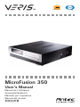
1
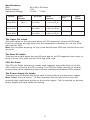
TM MicroFusion 350 User’s Manual Manuel de l’utilisateur Anwenderhandbuch Manuale per l’operatore Manual del usuario পᡅ䂀ᯢ Media Components At Antec, we continually refine and improve our products to ensure the highest quality. As such, your new case may differ slightly from the description in this manual. This isn’t a problem; it’s simply an improvement. As of the date of publication, all features, descriptions, and illustrations in this manual are correct. Disclaimer This manual is intended only as a guide for Antec’s Computer Enclosures. For more comprehensive instructions on installing the motherboard and peripherals, please refer to the user’s manuals that come with those components. MicroFusion 350 User’s Manual Quiet Desktop Slim Case The Power Supply The MicroFusion 350 comes with a 350-Watt power supply that features universal input. This includes dual 12V output rails that deliver safer and more reliable output to the system’s components, and generates at higher energy efficiency, reducing power consumption by up to 25%. This PSU has achieved 80 PLUS® Certification, the latest independent standard in power supply efficiency. In addition it features a variety of industrial-grade protective circuitry: OPP (over power protection), OVP (over voltage protection), UVP (under voltage protection), and SCP (short circuit protection). Setting Up Although caution has been taken to prevent sharp edges in your Antec case, we strongly recommend taking the appropriate time and care when working with it. Avoid hurried or careless motions. Please take reasonable precautions. 1. Place the case upright on a flat, stable surface. 2. Remove the thumbscrew from the back of the top panel. Slide the panel towards the rear to remove it from the case. 3. Inside the case you should see the power supply, some wiring with marked connectors (USB, PWR etc.), and installed I/O panel and a power cord. The Dual Chamber structure Upon opening the top panel, you will find that the case is divided into two separate chambers—the motherboard chamber and the HDD chamber. The power supply is designed to directly suck fresh air directly from outside the case. This unique feature combined with the dual chamber structure isolates heat and noise from each section, resulting in much quieter and cooler operation than a traditional desktop case. Installing the Motherboard This manual is not designed to cover CPU, RAM, or expansion card installation. Please consult the motherboard manual for specific mounting instructions and troubleshooting. The motherboard is located inside the main chamber with two 80 mm TriCool™ fans preinstalled right next to the CPU. 1. Lay the case down, with the open side facing up. The drive cages and power supply should be visible. 1 2. 3. 4. 5. 6. 7. 8. 9. Make sure you have the appropriate I/O panel for the motherboard. If the panel provided is not suitable for the motherboard, please contact the motherboard manufacturer for the correct I/O panel. Remove the cross bar on the motherboard chamber. Line up the motherboard with the raised mounting holes. There are three special brass standoffs pre-installed on the motherboard tray. Two of them are threaded and one without threads. Remove the motherboard by lifting it up. Remove any of the standoffs that are not needed. Place the motherboard back in the case and line it up with the standoffs and motherboard tray holes. Attach the motherboard to the threaded brass standoffs with the special nuts that come in your tool bag. Note: You do not need to fasten the unthreaded brass standoff. Fasten the motherboard to the raised mounting holes with the provided Philips-head screws. The motherboard is now installed. Connecting the Power and LED If the motherboard has a 20-pin power receptacle, detach the 4-pin attachment on the 24-pin power connector, see pictures 1 and 2. Before you connect the power supply to any of the devices, please consult the appropriate user manuals for the motherboard and other peripherals. 1. Connect the 24-pin Main Power Connector and Picture 1 Picture 2 the 4-pin or 8-pin 12V connector to the motherboard as needed. If the motherboard uses a 20-pin connector, detach the 4-pin attachment on the 24-pin power connector (see pictures 1 and 2). Note: the detachable 4-pin section cannot be used For 24-pin For 20-pin in place of a 4-pin +12V connector. motherboards motherboards 2. Connect the Reset switch (labeled RESET SW) to the motherboard at the RST connector. Polarity (positive and negative) does not matter for switches. 3. The Power Switch (labeled POWER SW) connects to the PWR connector on the motherboard. 4. The Power LED (labeled POWER LED) connector is located behind the Reset connector. For LEDs, colored wires are positive (+). White or black wires are negative (–). If the LED does not light up when the system is powered on, try reversing the connection. For more info on connecting LEDs to your motherboard, see your motherboard manual. 5. The Hard Drive LED (labeled HDD LED) connects to the hard drive activity header. Connecting the USB Ports You will find a single 10-pin connector on a cable attached to the front USB ports. This Intel standard connector is keyed so that it can’t be accidentally reversed as long as it is connected to a proper Intel standard motherboard header. Connect the 10-pin connector to the motherboard headers so that the blocked pin fits over the missing header pin. Note: Please check the motherboard manual for the USB header pin layout and make sure it matches the table below. If it does not match this Intel® standard, please visit Antec’s web store at http://www.antec.com/StoreFront.bok and search for part number 30095 to order a USB Internal Adapter Cable. This adapter will allow you to connect the front USB to your motherboard on a pin-by-pin basis. 2 Motherboard Pin Layout 1 2 9 10 Pin Signal Names Pin Signal Names 1 USB Power 1 2 USB Power 2 3 Negative Signal 1 4 Negative Signal 2 5 Positive Signal 1 6 Positive Signal 2 7 Ground 1 8 Ground 2 9 Key (No Connection) 10 Empty Pin Connecting the Audio Ports (AC’ 97 and HDA) The case has both an Intel standard 10-pin AC’ 97 connector and an Intel 10-pin HDA (High Definition Audio) connector. You can connect either the AC’ 97 or the HDA connector to your motherboard depending on the spec of the motherboard. If your motherboard supports Intel’s standard onboard AC’ 97 audio connector, plug the AC’ 97 connector directly onto the board. If your motherboard supports Intel’s High Definition Audio, plug HDA onto the board. See instruction below: Pin Assignment for Audio Ports (HDA and AC’97) 10 6 4 2 97531 Pin Signal Names (HDA) Pin Signal Names (AC’97) 1 MIC2 L 1 MIC In 2 AGND 2 GND 3 MIC2 R 3 MIC Power 4 AVCC 4 NC 5 FRO-R 5 Line Out (R) 6 MIC2_JD 6 Line Out (R) 7 F_IO_SEN 7 NC 8 Key (no pin) 8 Key (no pin) 9 FRO-L 9 Line Out (L) 10 LINE2_JD 10 Line Out (L) Locate the internal audio connectors from your motherboard or sound card. Consult your motherboard or sound card manual for the pin-out positions. Connecting the eSATA Port You will find a SATA connector on a cable attached to the front ports. This internal SATA connector is designed to connect to a standard SATA connector on your motherboard. 3 Hard disk Drive Installation The hard disk drive bracket with soft silicone grommets is inside the HDD chamber. It comes with a handle. The bracket is fastened by a thumbscrew on the side of the chamber and a Phillips head screw on the right side that holds it to the bottom of the case. 1. Remove the LCD display. You will need to pinch and hold the side latches while you push down on the top of the LCD bracket. The LCD will tilt back into the HDD chamber and you can easily lift it out. Be careful not to touch the face of the LCD display. 2. Remove the thumbscrew and Philips screw holding the HDD bracket. Lift the bracket from the chamber by the handle. 3. Mount your hard drive into the bracket through the bottom silicone grommets with the special screws provided. Don’t over-tighten. Over-tightening the screws will harm the vibration and noise reducing ability of the rubber grommets. 4. Find a 4-pin Molex or a SATA power connector on the power supply and connect it to the corresponding power connector on the hard disk drive. 5. Connect the data cable to the hard disk drive. 6. Place the HDD/bracket assembly back into the chamber. 7. Fasten the bracket using both screws provided. Note: Failing to use both screws could result in the HDD bracket coming loose and damaging the LCD display. 8. Reverse the procedure in step one to re-insert the LCD display. The LCD Display The MicroFusion 350 comes with a Liquid Crystal Display (LCD) Display. It comes with a built-in Microsoft MCE / Vista compatible IR receiver to work with your media center computer. Note: This LCD display is intended to be compatible with Microsoft MCE / Vista. The basic features include: System Information, Media Information, E-mail check, Daily news, City information (weather report), and graphic equalizer. The IR remote control is not included. 1. Make sure the power supply is off and unplugged before installing any hardware. 2. Connect the 3-pin power cable from the display to the 3-pin connector on the 24-pin ATX main power connector of the power supply. (Red, Purple, Black) Note: If you choose to swap the included power supply with another power supply, please visit Antec’s web store at http://www.antec.com/StoreFront. bok and search for part number 99999 to order a special 24-pin Extender. This extender has an extra cable that powers the display. 3. The display comes with a 4-pin internal USB adapter (see Picture 3) and a standard external USB connector. To connect the display, either: a.Connect the external connector to a standard USB port b.Check your motherboard USB header pin layout. Match the internal Picture 3 adapter to your motherboard header. Plug the internal adapter into the external connector and plug it in to your motherboard’s USB header. 4. To use the remote control to power on your system, please do the following: a.Find the single wires that are labeled MBR PWR and GND. This needs to be connected directly to your motherboard’s power switch connector b.The power switch from the case will need to be connected directly to the VFD 5. Plug in your power supply and turn it on. 6. Boot your computer. 7. Insert the provided driver CD into your optical drive and install the included software. You will need to restart after the driver has been installed. 4 5.25” Device Installation The MicroFusion 350 incorporates a rapid-release Flip Up Drive Cage for easy drive installation. The cage can hold one 5.25” device. To install an external 5.25” device: 1. Remove the flip-up drive cage. 2. Remove the drive bay cover. 3. Insert the 5.25” device into the cage. Make sure to use the front set of screw holes on the cage to mount the device. Fasten the drive with the screws included. 4. Find an appropriate power connector on the power supply and connect it to the corresponding power connector on the device. Cooling System The 80mm TriCool™ fans The MicroFusion 350 comes with three 80mm TriCool™ fans preinstalled. The 80mm TriCool Exhaust Fans: There are two fans next to the CPU so that the air is blowing out of the case. Please leave at least 1” (2.5cm) between the right side of the case and anything that would block the exhaust from these fans. Failure to do so may cause the chamber or CPU to overheat. The 80mm TriCool Intake Fan: There is one fan that sits in the HDD chamber to bring fresh air into the chamber to cool the hard disk drives. These fans have a three-speed switch that lets you choose between quiet, performance, or maximum cooling. (See specifications below.) Connect a large 4-pin connector from the power supply to the male 4-pin connector on the fan. Note: The default setting of the fans is Low. We recommend this speed to maximize quiet computing. Note regarding fan speed controllers and TriCool fans: The minimum voltage to start the fan is 5V. We recommend our users set the fan speed to High if the fan will be connected to a fan control device or to the Fan-Only connector found on some Antec power supplies. A fan-control device regulates the fan speed by varying the voltage to it. The voltage may start as low as 4.5V to 5V. Connecting a TriCool™ set on Medium or Low to a fan-control device may result in the fan not being able to start. The already lowered voltage from the fan control device will be further reduced by the TriCool circuitry below 5V. 5 Specifications: Size: Rated Voltage: Operating Voltage: Speed Input Current 80 x 80 x 25.4mm 12V 10.2V ~ 13.8V Air Flow Static Pressure Acoustical Noise Input Power High 2000 RPM 0.24A (Max.) 2.24 m³ / min (79 CFM) 2.54 mm-H2O (0.10 inch-H2O) 30 dBA 2.9 W Medium 1600 RPM 0.2A 1.59 m³ / min (56 CFM) 1.53 mm-H2O (0.06 inch-H2O) 28 dBA 2.4 W Low 1200 RPM 0.13A 1.1 m³ / min (39 CFM) 0.92 mm-H2O (0.04 inch-H2O) 25 dBA 1.6 W The Upper Air Intake There are vents on the top panel above the PCI expansion slots and CPU area. Fresh air will flow through them into the motherboard chamber to cool the VGA card and the CPU. Note: Do not place anything on top of the MicroFusion 350 that will block the top air vents. The Rear Air Intake There are vents right above the rear I/O panel and on the PCI expansion slot covers to bring in fresh air to help cool the CPU and VGA card. CPU Air Guide The CPU Air Guide and rear air intake work together to provide fresh air to the CPU cooler to enhance the CPU cooling. The CPU Air Guide consists of several sections that can be adjusted to best suit each individual motherboard CPU position. The Power Supply Air Intake There are vents on the left side of the case to bring fresh air into the power supply. Note: Please leave at least 1” (2.5cm) between the left side of the case and anything that could block airflow to the power supply. This is required so that the power supply will have sufficient cooling. 6 Antec, Inc. 47900 Fremont Blvd. Fremont, CA 94538 USA tel: 510-770-1200 fax: 510-770-1288 Antec Europe B.V. Sydneystraat 12 3047 AS Rotterdam The Netherlands tel: +31 (0) 10 462-2060 fax: +31 (0) 10 437-1752 Customer Support: US & Canada 1-800-22ANTEC [email protected] Europe +31 (0) 10 462-2060 [email protected] www.antec.com © Copyright 2007 Antec, Inc. All rights reserved. All trademarks are the property of their respective owners. Reproduction in whole or in part without written permission is prohibited. Printed in China.