1
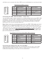
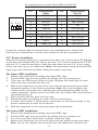
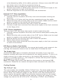
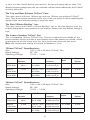
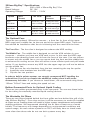
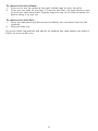
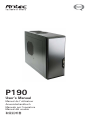
P190 User’s Manual Manuel de l’utilisateur Anwenderhandbuch Manuale per l’operatore Manual del usuario পᡅ䂀ᯢ At Antec, we continually refine and improve our products to ensure the highest quality. As such, it’s possible that your new case may differ slightly from the description in this manual. This isn’t a problem; it’s simply an improvement. As of the date of publication, all features, descriptions, and illustrations in this manual are correct. Disclaimer This manual is intended only as a guide for Antec’s Computer Enclosures. For more comprehensive instructions on installing the motherboard and peripherals, please refer to the user’s manuals that come with those components. P190 User’s Manual P190 – Advanced Super Mid Tower Case This case comes with the unique Antec dual power supply system, NeoLink™. Consisting of two power supply units –the NeoLink™ 650P and the NeoLink™ 550S – the NeoLink™ system has an output 1,200 watts. You will need to connect the NeoLink™ 650P to your motherboard and graphic card(s), and the NeoLink™ 550S to your peripheral drives and accessories such as fans or system monitoring/ control devices. Both power supplies come with an on/off switch. Please be sure to turn both power switches to the ON (I) position before you boot up your computer for the first time – your computer will not boot with only one of the NeoLink™ power supplies. Normally, you won’t need to switch to the OFF (O) position, since the power supply includes a soft on/off feature. This lets you turn your computer on and off by using the soft switch on your computer case. If your computer crashes and you can’t shut it down using the soft switch, you can switch the main power to the OFF (O) position on both power supplies to clear the fault, then reboot. Although care has been taken to prevent sharp edges in your Antec case, we strongly recommend taking your time and the appropriate care when working with it. Hurried or careless motion and use of excessive force, particularly when working inside areas you cannot into see clearly, are but a few examples of activity that should be avoided. Please use reasonable precaution. Setting Up 1. 2. 3. Place the case upright on a flat, stable surface with the rear of the case facing you. Remove the thumbscrews from the right side panel. Grip the panel at the top and bottom and swing it towards you to open the case. Remove the screws from the left side panel. Grip the panel at the top and bottom and swing it towards you to remove the left side panel. Note: Do not use your fingernails to pry or lift the panels. Inside the case you should see two separate chambers - the upper chamber for the motherboard, externally accessible drives and hard drives; and the lower chamber for the power supply and hard drives. You will also find some wiring with marked connectors (USB, PWR etc.), the installed I/O panel, a box containing the top fan spoiler and one set each of drive rails for a 5.25” drive and a floppy disk drive, and 1 a tool box attached to the upper HDD cage containing more hardware (screws, brass standoffs, spare silicone grommets, etc.). Cable Management You can route data and power supply cables through the holes behind the motherboard (MB) tray. 1. Remove both side panels. 2. Pass the cables through the holes behind the MB tray and use the cable ties to hold them in place. Installing the Motherboard This manual does not cover CPU, RAM, or expansion card installation. Please consult your motherboard manual for specific mounting instructions and troubleshooting. 1. 2. 3. 4. 5. 6. Lay the case down, with the open side facing up. The drive cages and power supply should be visible. Make sure you have the correct I/O panel for your motherboard. If the panel provided with the case isn’t suitable, please contact your motherboard manufacturer for the correct I/O panel. Line up your motherboard with the standoff holes and remember which holes are lined up. Not all motherboards will match with all the provided holes; this is normal and won’t affect its functionality. Remove your motherboard by lifting it up. Install standoffs as needed and put the motherboard back in. Screw in your motherboard to the standoffs with the provided Philips-head screws. Your motherboard is now installed. Connecting the Power and LED 1. 2. 3. 4. 5. Connect the power supply Main Power Connector and the 4-pin +12V connector to your motherboard as needed. Connect the Reset switch (labeled RESET SW) to your motherboard at the RST connector. Power Switch (labeled POWER SW) connects to the PWR connector on the motherboard. Power LED (labeled POWER LED) connector is located behind the Reset connector. On all LED’s, the colored wire is positive (+). Hard Drive LED I, LED II (labeled HDD I, HDD II) connectors: This case comes with two HDD LEDs. You may use these LEDs for two hard drives. Connecting the USB Ports You will find a single 10-pin connector on a cable attached to the front USB ports. This is an Intel® standard connector that is keyed so that it can’t be accidentally reversed when connected to a proper Intel® standard motherboard header. Connect the 10-pin connector to the motherboard headers so that the blocked pin fits over the missing header pin. Note: Please check the motherboard manual for the USB header pin layout and make sure it matches the table below. If it does not match this Intel® standard, please visit Antec’s web store at http://www.antec.com/StoreFront.bok and search for part number 30095 to order a USB Internal Adapter Cable. This adapter 2 will allow you to connect the front USB to your motherboard on a pin-by-pin basis. Motherboard USB Pin Layout 1 2 9 10 Pin Signal Names Pin Signal Names 1 USB Power 1 2 USB Power 2 3 Negative Signal 1 4 Negative Signal 2 5 Positive Signal 1 6 Positive Signal 2 7 Ground 1 8 Ground 2 9 Key (No Connection) 10 Empty Pin Connecting the IEEE 1394 (FireWire®, i.Link®) Port You will find a single 10-pin connector on a cable attached to the front IEEE 1394 connection. This is an Intel® standard connector that is keyed so that it can’t be accidentally reversed when connected to a proper Intel® standard motherboard header. Connect the 10-pin connector to the motherboard header so that the blocked pin fits over the missing header pin. Note: Please check the motherboard manual for your IEEE 1394 header pin layout and make sure it matches the table below. If you intend to connect the front FireWire port to an IEEE 1394 add-on card that comes with an external-type IEEE 1394 connector, you will need a FireWire Internal Adapter. To order one, please visit Antec’s web store at http://www.antec.com/StoreFront.bok and search for part number 30031. This adapter will allow you to connect the front IEEE 1394 port to the external-type connector. Pin Assignment for Front Panel IEEE 1394 Connector 1 2 9 10 Pin Signal Names Pin 2 Signal Names 1 TPA+ 3 Ground 4 Ground 5 TPB+ 6 TPB– 7 +12V (Fused) 9 Key (No Pin) 8 10 TPA– +12V (Fused) Ground Connecting the Audio Ports (AC’ 97 and HDA) There is an Intel® standard 10-pin AC’ 97 connector and an Intel® 10-pin HDA (High Definition Audio) connector, either of which can be connected to your motherboard depending on the spec of the motherboard. 3 Pin Assignment for Audio Ports (HDA and AC’97) 10 6 4 2 97531 Pin Signal Names (HDA) Pin Signal Names (AC’97) 1 MIC2 L 1 MIC In 2 AGND 2 GND 3 MIC2 R 3 MIC Power 4 AVCC 4 NC 5 FRO-R 5 Line Out (R) 6 MIC2_JD 6 Line Out (R) 7 F_IO_SEN 7 NC 8 Key (no pin) 8 Key (no pin) 9 FRO-L 9 Line Out (L) 10 LINE2_JD 10 Line Out (L) Locate the internal audio connectors from your motherboard or sound card. Consult your motherboard or sound card manual for the pin-out positions. 3.5” Device Installation With the front bezel facing you, swing the front door out. It can swing 270 degrees so the door will parallel with the side of the case. You will see there are four 5.25” and one 3.5” external drive bays. Inside the case there are two 3.5” drive cages, which can house up to six hard drives. Note: We recommend using the lower HDD cage to get the maximum possible cooling and quiet computing. The Upper HDD Installation. 1. 2. 3. 4. 5. 6. 7. 8. Remove the thumbscrew holding the upper HDD cage. Pull the HDD cage from its position by pulling the ring towards you. There are two HDD trays inside the cage. Squeeze the metal clips on each side of the tray and slide the tray out. Mount your hard drive into the drive tray with the special screws provided. dampening ability of the silicone grommets. Note: Do not over-tighten the screws as this will reduce the vibration and noise-dampening ability of the rubber grommets. Always mount the HDD with the thicker side of the silicone grommets facing up. Slide and lock the tray back into the case. Repeat the same procedure for other devices as necessary. Connect 4-pin molex or SATA power connectors on the power supply to the power connectors on each of the devices. Slide the cage back to the case and fasten the thumbscrew. The Lower HDD Installation. 1. 2. 3. 4. Remove the thumbscrew holding the lower HDD cage. Pull the HDD cage from its position by pulling the ring towards you. You can mount four hard drives vertically inside the cage. Mount your hard drive into the drive cage with the special screws provided. Note: Do not over-tighten the screws as this will reduce the vibration and 4 5. 6. 7. noise-dampening ability of the rubber grommets. Always mount the HDD with the thicker side of the silicone grommets facing up. Repeat the same procedure for other devices as necessary. Connect 4-pin molex or SATA power connectors on the power supply to the power connectors on each of the devices. Slide the cage back to the case and fasten the thumbscrew. External 3.5” Drive Installation There is one external 3.5” drive bay. 1. Carefully remove the plastic drive bay cover and metal plate covering the drive bay. 2. Find a pair of 3.5”drive rails from the box containing the top fan spoiler. 3. Mount the drive rails onto the sides of the 3.5” device. Make sure the metal portion is angled on the outside and facing forward. 4. Slide the device into the drive bay until it clicks into position. 5. Connect a small 4-pin connector from the power supply to the 4-pin connector on the floppy drive. 5.25” Device Installation There are four 5.25” drive bays that require a total of eight drive rails. 1. Carefully remove the plastic drive bay cover and the metal plate covering the drive bay. 2. Mount the drive rails onto the sides of the 5.25” device. Make sure the metal portion is angled on the outside and facing forward. 3. Slide the device into the drive bay until it clicks into position. 4. Mount other devices accordingly. 5. Connect 4-pin molex connectors from the power supply to the 4-pin connector on each of the devices. PCI-Express Add-in Card Holder There are two PCI-E card holders for the newest dual graphic card systems in the tool bag. An instruction sheet on how to install them is included as well. The Snake Light A white LED snake light is included to illuminate the inside of your case and features a flexible neck that can be adjusted to any desired position. To turn it on, simply connect it to a molex connector or the internal USB connector while the system is in standby mode (i.e., the computer is off but with the power supplies are plugged in to the AC outlet). Note: The Snake Light comes with both the 4-pin molex or the internal USB connectors. Please do not connect the light to both connectors the same time. Cooling System The TriCool™ fan: The case includes four installed 120mm TriCool™ fans. The three-speed fans let you choose between quiet performance or maximum cooling (see specifications below). Note: The minimum voltage to start the fan is 5V. We recommend our users to set the fan speed to High if you choose to connect the fan to a fan control device. A fan-controller regulates the fan speed by varying the voltage to it. The voltage may start as low as 4.5V to 5V. Connecting a TriCool™ set on Medium 5 or Low to a fan-control device may result in the fan not being able to start. The already lowered voltage from the fan controller will be further reduced by the TriCool™ circuitry below 5V. The Top and Rear Exhaust TriCool™ Fans The case comes with two 140mm top and one 120mm rear exhaust TriCool™ fans. They have speed switches at the top of the rear panel to allow adjusting the speed of the fans without having to open the case. The Side 200mm Big Boy™ fan: The case comes with a 200 x 30 mm Big Boy™ fan on the side panel to cool the hottest dual graphic card systems on the market. Please note the default setting is Low. The Lower Chamber TriCool™ Fan This is a standard 120mm TriCool™ fan. This fan is placed in the middle of the lower chamber which acts like a wind tunnel when side panels are closed, which guarantees the air will move from the front to the rear when the fan turns. Note: We recommend setting the speed to Medium or Low. 120mm TriCool™ Specifications: Size: Rated Voltage: Operating Voltage: Speed Input Current 120 x 120 x 25.4mm TriCool™ Fan DC 12V 10.2V ~ 13.8V Air Flow Static Pressure Acoustical Noise Input Power High 2000 RPM 0.24A (Max.) 2.24 m³ / min (79 CFM) 2.54 mm-H2O (0.10 inch-H2O) 30 dBA 2.9 W Medium 1600 RPM 0.2A 1.59 m³ / min (56 CFM) 1.53 mm-H2O (0.06 inch-H2O) 28 dBA 2.4 W Low 1200 RPM 0.13A 1.1 m³ / min (39 CFM) 0.92 mm-H2O (0.04 inch-H2O) 25 dBA 1.6 W 140mm TriCool™ Specifications: Size: Rated Voltage: Operating Voltage: Speed Input Current 140 x 140 x 25.4mm TriCool™ Fan DC 12V 10.2V ~ 13.8V Air Flow Static Pressure Acoustical Noise Input Power High 1500 RPM 0.28A (Max.) 2.68 m³ / min (94.6 CFM) 1.685 mm-H2O (0.066 inch-H2O) 31.8 dBA 3.36 W Medium 1100 RPM 0.20A 1.89 m³ / min (66.8 CFM) 0.934 mm-H2O (0.036 inch-H2O) 21.4 dBA 2.4 W Low 700 RPM 0.15A 1.33 m³ / min (47 CFM) 0.40mm-H2O (0.015 inch-H2O) 19.8 dBA 1.8 W 6 200mm Big Boy™ Specifications: Size: Rated Voltage: Operating Voltage: Speed 200 x 200 x 30mm Big Boy™ Fan DC 12V 10.2V ~ 13.8V Input Current Acoustical Noise Input Power 3.799 m³ / min 0.688 mm-H2O (134.11CFM) (0.027 inch-H2O) 29.4 dBA 3.6 W Air Flow Static Pressure High 800 RPM 0.3A Medium 600 RPM 0.17A 3.07 m³ / min (108.493 CFM) 0.397 mm-H2O (0.016 inch-H2O) 26.5 dBA 2.04 W Low 400 RPM 0.08A 2.34 m³ / min (82.612 CFM) 0.197mm-H2O (0.008 inch-H2O) 23.6 dBA 0.96 W The Optional Fans There are two optional 120mm fan mounts – a front fan (in front of the upper HDD cage) and a middle fan (at the rear end of the upper HDD cage). These two fans should be installed so that the air is blowing into the case from the front. The Front Fan - The front fan is designed to enhance the HDD cooling. The Middle Fan - The middle fan is designed to cool the VGA solution in your computer – whether you have one VGA card or two. In this case the HDD cage becomes a duct drawing fresh cool air from the front of the case. You can choose to mount only the middle fan or you can mount both the front and the middle fans to enhance the cooling as two fans will utilize a more efficient push and pull intake action. If you decide to mount any HDD into the upper cage you will not be able to use the middle fan. 1. Find the two fan wire brackets from the box containing the top fan spoiler. 2. Install the wire brackets into the HDD cage. 3. Clip the fan into position. In order to build a quieter system, we strongly recommend NOT installing the optional fans if you do not require the additional cooling since it will create unnecessary fan noise. If you choose to install them, we recommend using Antec 120mm TriCool™ fans and setting the speed to Low. Rubber Grommeted Ports for Optional Liquid Cooling There are two rubber grommeted ports in the rear panel. You can use these holes for the tubing for externally-mounted liquid cooling devices. The Washable Air Filters There are two filters located behind the front grilles and one behind the grill of the side 200mm Big Boy™. From time to time it will be necessary to wash the installed air filters as not washing them will result in higher system temperatures and possible stability problems. We recommend checking the air filter at least once a month initially. The frequency will change depending on environmental conditions and system usage, as users whose systems run 24/7 will likely have to check/wash more often than those who do not use their systems every day. 7 To remove the front filters: 1. 2. Push one of the fan grilles at the right middle edge to open the grille. There are two tabs on the filter. To remove the filter, use both hands to gently push the tabs downward. Slightly angle the top of the filter towards you before lifting it up and out. To remove the side filter: 1. 2. Open the side panel and disconnect the Molex fan connector from the fan carefully. Slide the filter out For more useful suggestions and advice on building this case please visit Antec’s FAQ’s at www.antec.com. 8 Antec, Inc. 47900 Fremont Blvd. Fremont, CA 94538 USA tel: 510-770-1200 fax: 510-770-1288 Antec Europe B.V. Sydneystraat 33 3047 BP Rotterdam The Netherlands tel: +31 (0) 10 462-2060 fax: +31 (0) 10 437-1752 Customer Support: US & Canada 1-800-22ANTEC [email protected] Europe +31 (0) 10 462-2060 [email protected] www.antec.com © Copyright 2007 Antec, Inc. All rights reserved. All trademarks are the property of their respective owners. Reproduction in whole or in part without written permission is prohibited. Printed in China.