1
BR-6641
4WAN+1LAN Load Balancer Router
User Manual
BR-6641 User Manual
Table of Contents
Chapter1 Quick Start ....................................................................................................4
1.1 Preparation ...............................................................................................................4
1.2 Access to the Web-based UI ....................................................................................6
1.3 BR-6641 Web-based UI Overview............................................................................8
1.4 How to use BR-6641 Web-based UI.......................................................................10
1.4.1 BR-6641 Operating Menu..........................................................................10
1.4.2 BR-6641 Rule/Filter/Policy Table............................................................... 11
Chapter 2 System........................................................................................................13
2.1 Summary.................................................................................................................14
2.2 Traffic Statistics .......................................................................................................16
2.3 Diagnostic Tools......................................................................................................17
2.4 Date&Time ..............................................................................................................20
2.4.1 Date&Time Setting.....................................................................................20
2.4.2 Busyhour Setting .......................................................................................21
2.5 Administration .........................................................................................................22
Chapter3 Network .......................................................................................................25
3.1 WAN Setting............................................................................................................26
3.1.1 Standard Mode ..........................................................................................28
3.1.2 DHCP Mode...............................................................................................31
3.1.3 PPPoE Mode .............................................................................................33
3.1.4 PPTP Mode ...............................................................................................35
3.1.5 Advanced Mode.........................................................................................37
3.2 LAN Setting.............................................................................................................39
3.3 DHCP Setting..........................................................................................................42
3.4 Host Names ............................................................................................................45
3.5 Service Names........................................................................................................47
3.6 IP Grouping .............................................................................................................49
3.7 Service Grouping ....................................................................................................51
Chapter 4 Service........................................................................................................53
4.1 Firewall....................................................................................................................54
4.2 Auto Routing ...........................................................................................................57
4.3 Virtual Server ..........................................................................................................60
1
BR-6641 User Manual
4.4 QoS .........................................................................................................................62
4.5 Per IP Max Connection ...........................................................................................66
4.6 Per IP Max Rate Control .........................................................................................68
4.7 Multihoming.............................................................................................................70
4.8 Internal DNS ...........................................................................................................75
4.9 SNMP......................................................................................................................77
4.10 UPnP.....................................................................................................................78
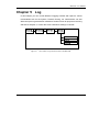
Chapter 5 Log..............................................................................................................79
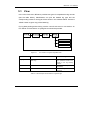
5.1 View ........................................................................................................................80
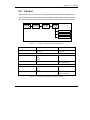
5.2 Control ....................................................................................................................81
5.3 Notification ..............................................................................................................84
2
BR-6641 User Manual
Copyright© by Edimax Technology Co, LTD. all rights reserved. No part of this
publication may be reproduced, transmitted, transcribed, stored in a retrieval system, or
translated into any language or computer language, in any form or by any means, electronic,
mechanical, magnetic,optical, chemical, manual or otherwise, without the prior written
permission of this company.
This company makes no representations or warranties, either expressed or implied, with
respect to the contents hereof and specifically disclaims any warranties, merchantability or
fitness for any particular purpose. Any software described in this manual is sold or licensed
"as is". Should the programs prove defective following their purchase, the buyer (and not
this company, its distributor, or its dealer) assumes the entire cost of all necessary servicing,
repair, and any incidental or consequential damages resulting from any defect in the
software. Further, this company reserves the right to revise this publication and to make
changes from time to time in the contents hereof without obligation to notify any person of
such revision or changes.
The product you have purchased and the setup screen may appear slightly different
from those shown in this QIG. For more detailed information about this product, please refer
to the User's Manual on the CD-ROM.The software and specifications subject to change
without notice. Please visit our web site www.edimax.com for the update. All right reserved
including all brand and product names mentioned in this manual are trademarks and/or
registeredtrademarks of their respective holders.
Linux Open Source Code
Certain Edimax products include software code developed by third parties,
including software code subject to the GNU General Public License ("GPL") or GNU
Lesser General Public License ("LGPL"). Please see the GNU (www.gnu.org) and
L
P
G
L
(www.gnu.org) Web sites to view the terms of each license.
The GPL Code and LGPL Code used in Edimax products are distributed
without any warranty and are subject to the copyrights of their authors. For details,
see the GPL Code and LGPL Code licenses. You can download the firmware-files at
http://www.edimax.com under "Download" page.
3
BR-6641 User Manual
Chapter1
Quick Start
At the first time using the product of BR-6641, you may confronted with
complicated settings which prevents you from starting well. This chapter will
explain the basic functionalities of BR-6641 and how to operate and configure the
system.It will also cover related subjects in network structures and hardware
installation which will help you during your setup of BR-6641.
1.1 Preparation
Before you get started, there are few things you need to know:
The position of the BR-6641 LAN Port: It has five network interfaces, the last port is
LAN Port which is marked on the machine.
The default IP address for LAN interface is 192.168.2.1
Your IP addresses for computers in the LAN should be changed to
192.168.2.2 (or 192.168.2.x) in order to avoid conflicts with the default LAN
port.
Connect your computers in the LAN to the BR-6641 with a cross-over cable,
which is a standard attachment.
To access the web-based administration UI, open http://192.168.2.1/ in your
Internet Explorer 6.0.
The default password for the administrator account is “1234”, and “5678” for
the monitor account. We strongly recommend you to modify the passwords at
the first time you log into the web-based UI. It is also a wise idea to write
down your changed passwords and keep them in a safe place in case you
forget them.
Check your network environment carefully before installing BR-6641. A
well-designed network environment with the necessary information such as
your network structure, IP addresses, and network segments information will
4
BR-6641 User Manual
help you complete the setup of BR-6641 parameters.
BR-6641 uses a web-based management user interface (Web-based UI).
Due to internal design constraints, you have to use MS Internet Explorer 6.0
(IE 6.0), or higher to access the Web-based UI. A screen resolution of
800x600 or higher is recommended.
Use a cross-over cable to access BR-6641 Web-based UI from the LAN port.
BR-6641 is shipped with two types of network cable in the box; one is a
cross-over and the other is a straight cable. Please use the cross-over cable
to connect to the computer and LAN port of BR-6641, the LED of the plugged
in port will turn on when properly connected.
5
BR-6641 User Manual
1.2 Access to the Web-based UI
The Web-based UI enables you to easily perform every configuration task. Follow
the steps below to access the Web-based UI.
1.
Connect your PC Ethernet LAN interface to LAN port of BR-6641 with a
cross-over cable. The default management LAN port of BR-6641 is LAN port.
2.
After powering on BR-6641, the LED of LAN port will turn to orange. This
indicates that it is on-line.
3.
Assign your PC Ethernet LAN interface with IP 192.168.2.2, subnet mask
255.255.255.0.
4.
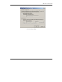
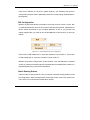
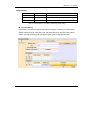
Check that the proxy setting of your IE browser is turned off, no proxy server
is required in order to access BR-6641 ’s Web-based UI. Open MS IE 6.0,
select Internet Option on the menu bar of Tools, click the Connection tab,
and then click LAN settings to open Local Area Network Settings dialog
box, under Proxy server, make sure proxy server is not selected.
5.
In the URL of IE 6.0, type in http://192.168.2.1 to access the Web-based UI.
6.
BR-6641 provides two types of user accounts:
Administrator - Has privileges to monitor and modify system parameters.
Monitor - Has privileges to monitor only.
BR-6641 allows up to 1 administrator and 1 monitor to access concurrently.
Default password for Administrator and Monitor are 1234 and 5678,
respectively. Please have your password change the first time you log in.
6
BR-6641 User Manual
Cancel the Proxy Setting
7
BR-6641 User Manual
1.3 BR-6641 Web-based UI Overview
After logging in, you will be able to start configuring or monitoring BR-6641
through the Web-based UI.
In order to help you to familiar with the basic operations, the explanations are as
follows:
The Web-based UI tasks are grouped into four categories. The categories are
located at the upper left-hand corner of Web-based UI task bar. These categories
cover all the configuration possibilities in BR-6641. The four categories are:
System
Network
Service
Log
In the later chapters, we will introduce the functions of these four categories. On
the first stage,you can login as Administrator in the Web-based UI and modify the
Administrator or Monitor password by performing the following: (1)Click System
and select Administration on task bar, (2) enter your new Administrator password
or Monitor password, after the system confirmation, using the new password next
time you log in.
What shall we do if we forget the new password?
If you forget your administrator password, use a Terminal (VT-100 compatible) to
establish the connection between PC RS - 232 series port and BR-6641 Console
interface, execute system reset to default.
Before you log into serial console, please complete following setting: Bits per
8
BR-6641 User Manual
second: 9600, Data bits: 8, Parity: None, Stop bits: 8, Flow control: None. The
serial console and Web-based UI use the same username and password pairs.
By default, the password of “Administrator” is 1234, and the password of “Monitor”
is 5678. If the password is changed via the Web-based UI, it will also be changed
in the serial console. In case you lose your password, you can use the username
“reset” and password “BR-6641_edimax” to log into serial console and reset the
system to default.
Open the IE browser to access the Web-based UI
Note: Please remember the changed password , otherwise it is not possible to
access the BR-6641 management interface.
9
BR-6641 User Manual
1.4
How to use BR-6641 Web-based UI
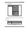
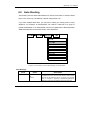
This section describes the operations and arrangement of Web Based UI, figure
1-2 displays the operating menu of BR-6641 Web-based UI system.
BR-6641
1.4.1
Web Based UI Operating Menu Items
BR-6641 Operating Menu
The task bar of operating menu contains five categories, which are System,
Service, Network, Log, each category has these own menu, “System /
Summary”
in
figure
1-2
indicates
the
current
working
menu,
while
“Administrator 192.168.2.1” indicates login account is Administrator at system
name of 192.168.2.1.
Select the “Logout” from up right corner to exit the system.
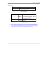
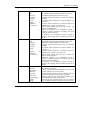
Apply, Reload, Help/Hide Help buttons are always displayed on the operating
menu, the functions are as described below:
Button
Function
After modifying the parameters of specific menu
page, click this button to save your changes to
memory, the old settings will also be saved.
10
BR-6641 User Manual
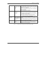
Click this button to recover the old settings
which apply has saved.
Click the Help button to display the on-line help
of the current page, the on-line help information
will automatically swap when you change the
function page or language.
Click Hide Help to hide the on-line help
information.
Table 5.0
Buttons
Note: The Apply and Reload buttons here are active only on certain pages, any
parameters modified without click Apply will not be saved to the memory.
Remember to click Apply when you are ready to move to the next page menu
or logout.
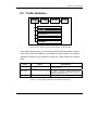
1.4.2
BR-6641 Rule/Filter/Policy Table
Orders of Rules/Filters/Policies
BR-6641 provides a rule table for you to perform the tasks like system parameter
or service policies. Often you are required to add or delete rules of your own. In
general, when you have multiple rules in a table, BR-6641 matches these rules
from top to bottom. That is, the rules at the top of the table are given a higher
precedence. Thus, to achieve the outcome of your desire, the more specific rules
should be placed on top of the less specific rules.
You will see in this table a few icons and their meanings:
Add a new rule below the current rule.
Move the current rule one row down.
Move the current rule one row up.
Delete the current rule.
11
BR-6641 User Manual
Write a note for the current rule.
Table 5.1
Operating Rules
When you add a new rule, the newly added rule will be placed right below the
current rule. Moving the rule up or down will swap positions between the upper and
lower rules.
Checkbox
It is quite common that you see the following checkboxes in some tables. These
checkboxes indicate whether certain functions are enabled or not. A red check sign
inside a checkbox stands for “enabled”, and an empty checkbox means “disabled”.
For example, you can enable logging for a rule by checking its checkbox in the rule
table.
The function is disabled.
The function is enabled.
Table 5.2
Check Box
So far, we have only mentioned the basic operations of the Web-based UI. In the
next section, we will talk more on how to integrate BR-6641 into your present
network environment.
12
BR-6641 User Manual
Chapter 2
System
In this chapter, you will learn how to configure system settings. System settings are
the fundamental configurations of the BR-6641 system. They have to be specific in
order for the system to work properly. Examples are provided here to help you to
fulfill the configuration.
Figure 3.1 The Location of “System/Summary” on the Menu Bar
13
BR-6641 User Manual
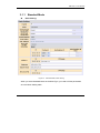
2.1 Summary
[Summary] is in the submenu of [System], which helps the Administrator to know
the system information. While logging in the Web UI, System/Summary is the first
page you see when you log into BR-6641’s web-based UI.
[Summary] provide the following information:
System Information
Category
System Information
Field
Description
Version
The Firmware Version.
Serial Number
The Serial number.
Up Time
Time since the last reboot.
Connections
Number of total connections.
CPU Usage %
CPU usage in percentage.
Packets/Second
Number
second.
of
packets
served
per
Table 3.1 System Information
Note: Connections may jump up to over 100 when BR-6641 is starting up. This is
due to many ICMP packets sent out by BR-6641 to test the network. It will drop
back to normal there after.
14
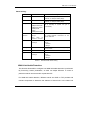
BR-6641 User Manual
WAN Link State
The section on WAN Link State shows the current status of each and every WAN
link. Each WAN link is represented as a color-coded block with the following color
coding scheme to indicate its status. The allowed number of WAN Link is also
shown here.
y
Green: Active WAN link.
y
Red: Broken WAN link.
y
Black: WAN link not in use.
15
BR-6641 User Manual
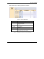
2.2 Traffic Statistics
Figure 3.2 The Location of “System/Traffic Statistics” on the Menu Bar
In the traffic statistics page, you can inspect real-time traffic information sorted by
traffic class over each WAN link. The statistics of traffic classes in the table is
adjusted accordingly by your selection of traffic type - either inbound or outbound
traffic.
Field
Traffic Type
Value
Descriptions
Inbound
The direction of traffic flow – either inbound traffic
or outbound traffic.
Outbound
Traffic Class
WAN Link
The names of the traffic classes defined on the
QoS page. The rest of unclassified information is
labelled as “Default Class”.
1, 2…
The total number of WAN links you want to inspect.
Table 3.2 The Description of the fields on the Statistics/Traffic Page
16
BR-6641 User Manual
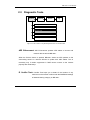
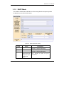
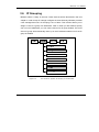
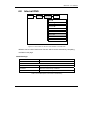
2.3 Diagnostic Tools
System
Network
Service
Log
Summary
Traffic Statistics
Diagnostic Tools
Date & Time
Administration
Figure 3.3 The Location of “System/Diagnostic Tools” on the Menu Bar
ARP Enforcement: ARP Enforcement updates ARP tables of servers and
network devices around BR-6641.
When the Enforce button is pushed, BR-6641 sends out ARP packets to the
surrounding servers or network devices to update their ARP tables. This is
necessary only if certain equipments in DMZ cannot connect to the Internet
properly after initial setup.
IP Conflict Test:IP Conflict Test helps you to detect if the location of any
machines on the network conflicts with the DMZ/WAN settings
of Network Setting category on BR-6641.
17
BR-6641 User Manual
Push Test button to begin the test. The result of the test is one of the following:
Everything is ok.
BR-6641 discovers that a machine in DMZ conflicts with Network Setting on
BR-6641. For example, a public IP address should be in WAN but is used by
a machine in DMZ. An error message with the conflicting IP address and
MAC address of the machine will be displayed.
BR-6641 discovers that a machine in WAN conflicts with Network Setting on
BR-6641. For example, a public IP address should be in DMZ but is used by a
machine in WAN. An error message with the conflicting IP address and MAC
address of the machine will be displayed.
Ping: Ping is used to detect network condition by sending ICMP packets to a
target device.
You may specify a target device in the Target IP field. It accepts either an IP
address or a host name. Select a network interface, WAN or LAN. If it is WAN,
select WAN link number in Index field. As to the error message about ICMP, please
refer to the concerned document.
Note: If a domain name is used to ping, a DNS server has to be specified in [Network ]→[Host
Names].
Trace Route: Trace route is used to detect network condition by showing the
routing path from BR-6641 to the target device.
You may specify a target device in the Target IP field. It accepts either an IP
address or a host name. Select a network interface, WAN or LAN. If it is WAN,
select WAN link number in Index field. For ICMP related error messages, please
18
BR-6641 User Manual
refer other materials.
You may specify a target device in the Target IP field. It accepts either an IP
address or a host name.
You may specify a target device in the Target IP field. It accepts either an IP
address or FQDN. Select a network interface, WAN or LAN. If it is WAN, select
WAN link number in Index field.
Note: If a domain name is used to traceroute, a DNS server has to be specified in [Network ]
→[Host Names].
Arping: Arping is used to detect the MAC address of a computer.
You may specify a target device in the Target IP field. It accepts either an IP
address or a host name. Select a network interface (WAN, LAN). If it is WAN,
select WAN link number in Index field. For ARP related error messages, please
refer other materials.
Note: If a host name is used in Target IP field, then a DNS server has to be specified in
[Network ]→[Host Names].
19
BR-6641 User Manual
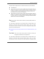
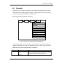
2.4 Date&Time
System
Network
Service
Log
Summary
Traffic Statistics
Diagnostic Tools
Date & Time
Administration
Figure 3.4 The Location of “System/Date/Time” on the Menu Bar
2.4.1
Date&Time Setting
In this page, you can set up time related configurations.
For time zone information, You should pick the region first and then the city you are
located in (or a city of the same time zone as you). For example, if you are located
in Hawaii, select ”US” in the left list and then choose “Hawaii” in the right list.
BR-6641 can use the NTP protocol to get time from the Internet. You can select a
time server from the list or add your preferred time server to the list. With NTP,
BR-6641 automatically adjusts its time when necessary. On the other hand, you
can push the Synchronize Time button to adjust time immediately.
20
BR-6641 User Manual
2.4.2
Busyhour Setting
Busyhour Setting is very important from a MIS manager’s point of view. It provides
a tool for you to define two time segments: busy-hour and idle-hour. All other
rule-based services such as bandwidth management and auto-routing can take
advantage of this function. For example, you can define 9:00 am to 5:00 pm,
Monday through Friday to be busy-hour. Then you can reserve bandwidth to
business-related network traffic during busy-hour and relax the rule on idle-hour.
Field
Default Type
Value
Description
Idle
Define default type to be either Idle or
Busy hour.
Busy
Rule
-
You set the time segment rules in this
table. They are matched in sequence
on a first-match basis. If none of the
rules match, the default type is used.
Weekday
Sunday
Day of the week.
Monday
Tuesday
Wednesday
Thursday
Friday
Saturday
Any Day
From
<Hour/Minute>
The start time.
To
<Hour/Minute>
The end time.
Busy
If the current time matches the day of
the week and in between From and To
time, then Type field applies.
Type
Idle
Table 3.3 Busyhour Setting
21
BR-6641 User Manual
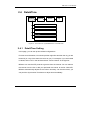
2.5 Administration
Figure 3.5 The Location of “System/Administration” on the Menu Bar
In this page, you can do a few administrative tasks. First, you can change the
password of Administrator and Monitor accounts. Every BR-6641 comes with the
same passwords initially. To avoid any security risks, it is absolutely necessary to
change passwords before putting your BR-6641 on-line.
From time to time you might receive BR-6641 firmware updates from AscenVision
or your system integrator. Just push the Update button and follow the instructions
on the screen to update.
You can save your current configurations to a file and restore it later. We
recommend that you save your working configuration before modifying the
configuration. In case of configuration error (such as rules that block you from
accessing BR-6641 anymore), you can always reset the machine to factory default
state using the console command and quickly restore to your original
configuration.
22
BR-6641 User Manual
You can reset BR-6641 to its factory default state. In doing this, you will lose your
entire customized configuration.
Finally, you can reboot BR-6641. Due to web interface limitations. There will not be
any messages after you have rebooted the system. Wait two minutes or so and try
to re-connect to BR-6641 using the browser.
Administrator Password:
Here, you can add, delete, or modify administrator’s account and password.
Field
Value
Description
New Password
Enter the new password here.
Confirm
Enter the new password here again.
Set Password
Click the button to enable the new
password.
Monitor Password:
Here, you can add, delete, or modify Monitor’s account and password.
Field
Value
Descreption
Password
Enter the new password here.
Confirm
Enter the new password here again.
Set Password
Click the button to enable the new
password.
Firmware Update:
Push the Update button and follow the following instruction to start the firmware
update process.
Obtain the latest firmware pack from your SI or VAR
23
BR-6641 User Manual
Log on to Web UI as the Administrator and go to function [System]→ [Administration].
Use [Browse...] to select the path to the new firmware image, then select [Upload].
The firmware update will take a while so be patient. During the update process BE
SURE not to turn off the system or pull the power plug. You should also NOT click
on [Upload] button.
Note:Update will succeed when ¬the “Update succeeded” message appears. At this time
please power off and then on again the system to restart BR-6641 with the new
firmware.
Configuration File:
Push Save button to save current configuration into a file. Push Restore button to
restore the configuration back from a saved configuration file. See Appendix 2 for
more information.
Log into BR-6641 as Administrator. In the Web UI, go to [System]→
[Administration] and select [Configuration File] → [Save] to backup the Config File
to your local machine/notebook.
To restore to the previously saved config file, go to [Configuration File] → [Restore],
select [Browse...] to pick the saved config file and select [Upload]. Notice: DO NOT
to turn off the power during the config file upload process, or repetitively select the
[Upload] button.
Restart BR-6641 to effect the configuration.
Maintenance:
Push Factory Default button to reset BR-6641 configuration to its factory default. You
can do the same operation using resetconfig command in console. Push reboot
button to reboot BR-6641.
24
BR-6641 User Manual
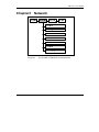
Chapter3
Network
Figure 3.1
The Location of “Network” on the Menu Bar
25
BR-6641 User Manual
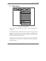
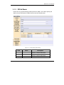
3.1 WAN Setting
Figure 3.2 System / Network Setting
[WAN Setting] is quite important part for BR-6641. The relavent parameter is
defined here.
The configuration is done one WAN link at a time. However, you can apply all the
changes at once at the end. You can select a WAN link by selecting the link
number in a WAN Link drop-down box. For each WAN link, you will fill out a few
tables with correct information from its ISP.
The first thing you have to decide is the WAN type. The rest of the settings will
change based on the WAN type you have selected. BR-6641 supports the
following WAN types:
26
BR-6641 User Manual
After connecting the WAN Link to the machine, WAN No. need to be defined in [Basic
Setting]. WAN is to be different for different type of WAN. BR-6641 provide the following
choices:
Standard
DHCP
PPPoE
PPTP
Advanced
Figure 3.3 WAN Setting / Basic Setting
27
BR-6641 User Manual
3.1.1
Standard Mode
Basic Setting:
Figure 3.4 Standard Mode / Basic Setting
When you select Standard Mode as the WAN Type, you need to fill the parameters
as in the Basic Setting table.
28
BR-6641 User Manual
Basic Setting:
Field
Value
Description
Down Stream
The down stream (inbound) bandwidth of the
WAN link, for example 25600 (Kbps).
Up Stream
The up stream (outbound) bandwidth of the
WAN link, for example 25600 (Kbps).
Port Speed
Auto
10Mbps/Half duplex
10Mbps/Full duplex
The speed and duplex of WAN Port. You can
set it manually or system can got it
automatically.
100Mbps/Half
duplex
100Mbps/Full duplex
Health
Detection
Never
Always
Only
when
no
packet is received
Address
IP Address
This function is used to configure the WAN
link health detection mechanism for the
specific WAN link.
Input the IP Address of BR-6641 in WAN. It
can be:
IP Range
IP Address
IP Range
Gateway
Input the predefined
211.21.40.254.
Subnet Mask
Input the Subnet Mask.
IP(s) in DMZ
IP Address
Gateway,
e.g.:
Input the IP Address of BR-6641 in DMZ. It
can be:
IP Range
IP Address
IP Range
Table 3.1
Standard Mode / Basic Setting
WAN Link Health Detection:
This function allows MIS to configure how WAN link health detection is performed.
By fine-tuning certain parameters, an MIS can adjust BR-6641 to match a
particular network structure and/or a particular ISP.
For WAN link health detection, BR-6641 sends out ICMP or TCP packets and
monitors responses to determine the statuses of those links. In the WAN Link
29
BR-6641 User Manual
Health Detection page, the following parameters are available:
Figure 3.5 WAN Link Health Detection
Field
Description
Never
BR-6641 assumes a healthy WAN and stop monitoring
ICMP and TCP packets.
Always
BR-6641 will always do the health detection according to
the rules.
Only when no packet
is received
If BR-6641 detects no inbound WAN traffic, it will start the
health detection.
Protocol
Choose either ICMP or TCP as methods for WAN health
detection.
Destination
Input the destination IP Address.
Port/Number of Hops
Set the Hops if ICMP is selected.
Set the Port number if TCP is selected.
Table 3.2
The description of the field in WAN Link Health Detection
30
BR-6641 User Manual
3.1.2
DHCP Mode
This model is enabled when BR-6641 is a client using DHCP to acquire a dynamic
IP address from an ISP's DHCP server.
Figure 3.6 DHCP Mode / Basic Setting
Field
Value
Description
Down Stream
The down stream (inbound) bandwidth of the
WAN link, for example 25600 (Kbps).
Up Stream
The up stream (outbound) bandwidth of the
WAN link, for example 25600 (Kbps).
Port Speed
Auto
10Mbps/Half duplex
10Mbps/Full duplex
The speed and duplex of WAN Port. You can
set it manually or system can got it
automatically.
100Mbps/Half
duplex
31
BR-6641 User Manual
100Mbps/Full duplex
Health
Detection
Never
Always
Only
when
no
packet is received
Clone MAC
MAC
This function is used to configure the WAN
link health detection mechanism for the
specific WAN link. Please refer to Chapter
3.2.1 WAN Link Health Detection.
Normally DHCP will assign IP dynamically.
Static IP, however, can be assigned to the
WAN link via the DHCP server with MAC
address binding. You can enable the 'Mac
Cloning' option to force the DHCP server to
assign the static IP according to the
BR-6641's MAC address.
xx-xx-xx-xx-xx-xx
Input the Clone MAC Address.
Table 3.3
DHCP Mode
32
BR-6641 User Manual
3.1.3
PPPoE Mode
PPPoE is a very popular bridging mode protocol for ADSL. You need to specify the
ADSL account information to obtain IPs from the ISP PPPoE server.
Figure 3.7 PPPoE Mode / Basic Setting
Field
Value
Description
Down Stream
The down stream (inbound) bandwidth of the
WAN link, for example 25600 (Kbps).
Up Stream
The up stream (outbound) bandwidth of the
WAN link, for example 25600 (Kbps).
Port Speed
Auto
The speed and duplex of WAN Port. You can
33
BR-6641 User Manual
10Mbps/Half duplex
10Mbps/Full duplex
set it manually or system can got it
automatically.
100Mbps/Half
duplex
100Mbps/Full duplex
Health
Detection
Never
Always
Only
when
no
packet is received
This function is used to configure the WAN
link health detection mechanism for the
specific WAN link. Please refer to Chapter
3.2.1 WAN Link Health Detection.
User
Input the user’s account assigned by ISP.
Password
Enter the password of the account.
Automatically
Obtain
IP
Address
Enable this function, and ISP will provide IP
Address, Gateway and Netmask.
Address
Note: If your ADSL is dynamic IP, check the
checkbox. If it is static IP, please do not.
x.x.x.x
Input the IP Address assigned by ISP.
Table 3.4 PPPoE Mode
34
BR-6641 User Manual
3.1.4
PPTP Mode
This model is enabled when BR-6641 is access to PPTP server via Internet.
Figure 3.8 PPTP Mode / Basic Setting
Field
Value
Description
Down Stream
The down stream (inbound) bandwidth of the
WAN link, for example 25600 (Kbps).
Up Stream
The up stream (outbound) bandwidth of the
WAN link, for example 25600 (Kbps).
35
BR-6641 User Manual
Port Speed
Auto
10Mbps/Half duplex
10Mbps/Full duplex
The speed and duplex of WAN Port. You can
set it manually or system can got it
automatically.
100Mbps/Half
duplex
100Mbps/Full duplex
Health
Detection
Never
Always
Only
when
no
packet is received
This function is used to configure the WAN
link health detection mechanism for the
specific WAN link. Please refer to Chapter
3.2.1 WAN Link Health Detection.
User
Input the user name for login VPN.
Password
Input the password for login VPN.
Connection ID
Input the ID for Connection through VPN.
Server IP
x.x.x.x
Input the PPTP Sever IP Address for VPN
dialing.
My IP
x.x.x.x
Input the IP Address of the local machine.
My
mask
subnet
Input the Subnet Mask of the local machine.
Table 3.5 PPTP Mode
36
BR-6641 User Manual
3.1.5
Advanced Mode
Advanced mode is used where BR-6641 is connected with a router via its private
IP and its actual public IP deployed in DMZ.
Figure 3.9 Advanced Model / Basic Setting
37
BR-6641 User Manual
Field
Value
Description
Down Stream
The down stream (inbound) bandwidth of the
WAN link, for example 25600 (Kbps).
Up Stream
The up stream (outbound) bandwidth of the
WAN link, for example 25600 (Kbps).
Port Speed
Auto
10Mbps/Half duplex
10Mbps/Full duplex
The speed and duplex of WAN Port. You can
set it manually or system can get it
automatically.
100Mbps/Half
duplex
100Mbps/Full duplex
Health
Detection
Never
Always
Only
when
no
packet is received
This function is used to configure the WAN
link health detection mechanism for the
specific WAN link. Please refer to Chapter
3.2.1 WAN Link Health Detection.
Subnet in WAN
Address
IP Address
IP Range
Input the private IP address of BR-6641
connected with the router. There are two
options available:
IP Address
IP Range
Gateway
Input the predefined
192.168.99.1.
Subnet Mask
Input the Subnet Mask.
Gateway,
Public-IP Subnet in DMZ
IP
Input the public IP of BR-6641 in DMZ
Subnet Mask
Input the Subnet Mask.
Table 3.6 The description of the fields in Advanced Mode
38
e.g.:
BR-6641 User Manual
3.2 LAN Setting
Figure 3.10
Network/LAN Setting
Basic Subnet
The table of Basic Subnet allows you to specify one or more private subnets that
connect to BR-6641 directly.
Figure 3.11
LAN Setting / Basic Subnet
39
BR-6641 User Manual
Input the IP Address of LAN Port in [Basic Subnet] - [IP Address] and input the
corresponding subnet mask in [Netmask]. Select the corresponding Speed/Duplex in
[Port-Speed].
RIP Configuration
BR-6641 support RIP (Routing Information Protocols) for both version 1 and 2. RIP
v1 is the basic definition while v2 has some functional enhancements. Please refer to
IETF’s official documents for the complete definition of RIP. If your private LAN
subnet supports RIP, you need to also enable BR-6641’s RIP function, by doing as
follows:
Figure 3.12
LAN Private Subnet / RIP Configuration
If the router in LAN enable RIP v1, check the checkbox in front of RIP v1. If the router
in LAN enable RIP v2, check the checkbox in front of RIP v2.
BR-6641 supports the transmission of RIP packets. If the authentication is enabled
on RIP v2, password must be entered in [Authentication Password] field. If there is no
predefined password, just leave the field blank.
Static Routing Subnet
If there is static routing subnet in LAN, you need to use Static Routing Subnet to fulfil
the configuration. Static Routing Subnet means that a router route out a subnet from
LAN, which is not connected to the BR-6641 directly.
40
BR-6641 User Manual
Note: DMZ is virtual area, which is in the port with LAN. DMZ support the public IP Address. The
public IP support only one IP range, which do not support multi-IP range Routing.
Example:
Figure 3.13
Figure 3.14
LAN Private Subnet / Static Routing Subnet
LAN Private Subnet / Static Routing Subnet Setting
41
BR-6641 User Manual
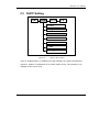
3.3 DHCP Setting
Figure 3.15
Network / DHCP Setting
Click on “Enable DHCP” to enable this function. BR-6641 is a client using DHCP to
acquire a dynamic IP address from an ISP’s DHCP server. The following is an
example of how you set it up.
42
BR-6641 User Manual
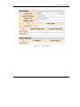
Figure 3.16
DHCP Setting
43
BR-6641 User Manual
Field
Description
Lease Time
Input the Lease Time by hour.
Default
Gateway
Input the Default Gateway. The Client will take this address as
Gateway when DHCP is enabled.
Note: This address should be in the subnet with LAN’s
Subnet
Netmask
Input the IP Address of DNS. The Client will take this address as DNS
Server when DHCP is enabled.
Domain Name
Input the Domain Name of DHCP.
DNS
Input the IP Address of DNS.
Range Start
Input the dynamic Range Start and Range End assinged for LAN
host, e.g.
-Range End
192.168.10.53 -199.168.10.100.
IP
-MAC
Address
If the host in LAN require a stable IP Address, input IP Address and
IP-MAC Address.
Table 3.7 DHCP Setting
44
BR-6641 User Manual
3.4 Host Names
Figure 3.17
Network / DHCP Setting
This function is to define the the name for system, specific IP and IP group. These
defined names will appear in sub-menu of source and destination in Firewall,
Multihoming, etc.
System Name:
Field
Description
Name
Input the host name of the BR-6641.
Domain
Input the domain of the BR-6641.
DNS
Input the IP Address of DNS, BR-6641 will use it to
resolve machine names to obtain IP addresses
Table 3.8 System Name
45
BR-6641 User Manual
Named IP Addresses:
Field
Description
Name
Input the name which is to be substitute for the IP
address.
Address
Specify the IP Address. It can be:
IP Address
IP Range
Table 3.9 System Name
46
BR-6641 User Manual
3.5 Service Names
Figure 3.18
Network / Service Names
This function is to configure the name, protocol and other parameters of service.
(BR-6641 has a default list of commonly used services.) These defined names will
appear in sub-menu of service in Firewall, Multihoming, etc..
Service List:
Field
Value
Description
Name
-
Input the name
PING,FTP…
Protocol
Protocol Number
Select protocol for service:
ICMP
Protocol Number, e.g. ICMP Protocol
Number is “1”, TCP is “6”. For more
information, please refer to concern
document.
TCP
UDP
47
of
the
service,
e.g.
BR-6641 User Manual
ICMP: The service used ICMP, e.g. Ping.
TCP: The service used TCP, e.g. FTP.
UDP: The service used UDP.
Parameter
Number
Specify the parameter for different Protocols.
Type
Number: Input Protocol Number.
From…To
Type: Input the service type of ICMP.
From..To: Input
TCP/UDP.
the
Port
Number
of
Single Port Number:
A range of Port Number: Input the start port
number in [From] and the end port number in
[To].
Table 3.10 Service Name
48
BR-6641 User Manual
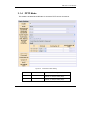
3.6
IP Grouping
BR-6641 offers a variety of services. These services will be discussed in the next
chapter. In order to help IT manager configure services efficiently, BR-6641 provides
a few management tools. IP Grouping is one of them. This function allows you to
assign a name to a group of IP addresses. Later on when you are asked to specify
one or more IP addresses, you can use the name of an IP group instead. The name
of this IP group will automatically show up in the IP address selection list if the IP
group is enabled.
Figure 3.19
The Location of “System / IP Grouping” on the Menu Bar
49
BR-6641 User Manual
IP Grouping:
Feild
Group Name
Description
Input the name of the group, then it will appear in the
service menu and the relevant options.
Note: You can set at most 5 groups.
Table 3.11 IP Grouping
Rules Setting:
Field
IP address
Group
Value
Description
<IP
address>
Input IP address - One single IP address, or
an IP address range in the format of
xxx.xxx.xxx.xxx-yyy.yyy.yyy.yyy
Or
a
subnet
in
the
format
of
xxx.xxx.xxx.xxx/yyy.yyy.yyy.yyy
belong to
Select the in group which the IP Address
belongs to.
not belong to
Table 3.12 Rules Setting
Note: The difference between the setting of and the setting of [Named IP Addresses] is that the
format in [Named IP Addresses] can only be a range of IP Address, while [IP Group]
provide several types of format. BR-6641 give more priority to the group in [Named IP
Addresses]. It is recommended to use groups defined in [Host Name].
50
BR-6641 User Manual
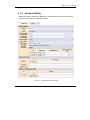
3.7 Service Grouping
This function allows you to assign a name to a group of TCP ports, UDP ports, and/or
ICMP. Later on when you are asked to specify a port, you can use the name of the
service group instead. The name of a service group will automatically show up in the
port selection list if the service group is enabled.
Figure 3.20
The Location of “System / Service Grouping” on the Menu Bar
Service Grouping:
Field
Value
Description
Group Name
<name>
Input the group name, e.g. MSN File
Transfer, then it will appear in the
service menu and relevant options.
Note: You can set at most 5 groups.
Service
ICMP
Define the assigned TCP, UDP, and
ICMP as a group for the usage in the
TCP@
51
BR-6641 User Manual
Group
UDP@
service menu. The format is port (xxx)
for single Port and port (xxx-yyy) for a
range of port, e.g. 6891-6900.
belong to
Define if the the Port IPAddress in
former Field belongs to the group.
not belong to
Table 3.13 Service Grouping
For example, you can set up a service group called “MSN File Transfer”. Its ports are
TCP 6891 to 6900. You need to fill TCP@6891-6900 into Service field.
52
BR-6641 User Manual
Chapter 4
Service
After having set up your network environment in the previous chapter, we will now
look into the services provided by BR-6641.
These services can help you manage your network more efficiently and effectively.
In figure 4.1, you can see a list of functions BR-6641 is capable of. These services
play an important role in daily network administration. For example, Firewall protects
your network from hacker attacks. It also improves your network security by filtering
out unwanted service types. Routing policies can maximize the utilization of your
network resources and assign routing paths accordingly based on the status of the
network. QoS is another feature that you can set up to manage the traffic limit for a
given TCP/UDP service (e.g. HTTP, FTP). This feature helps you allocate available
bandwidth for each type of service and maximize the efficiency of your network.
Multihoming provides a safeguard against failures in WAN links. Requests to the
internal servers (e.g. WWW server) will be dispatched evenly on every live WAN link.
If one of them fails, the internal servers can still be reached via other live links.
Figure 4.1
The Location of “System/Summary” on the Menu Bar
53
BR-6641 User Manual
4.1 Firewall
[Summary] is in the submenu of [System], which helps the Administrator to know the
system information. While logging in the Web UI, System/Summary is the first page
you see when you log into BR-6641’s web-based UI.
[Summary] provide the following information:
Figure 4.2 The Location of “Service/Firewall” on the Menu Bar
You can add as many rules as you like in the list. For each rule, you can enable or
disable it individually. The rules are matched from top to down, that is, the rules
listed at the top of the list are given higher precedence.
Field
When
Value
Busy
Idle
All-Time
Description
There are three options available: Busy hour, idle hour, and
All-times. Please refer to Chapter 2 [System]→[ Date/Time]
for setting up the definition of busy or idle hours.
54
BR-6641 User Manual
Source
Any address
Packets sent from the specified source will be matched:
LAN
Any Address: Match all packets regardless of its source.
WAN
LAN: Match all packets that come from the LAN.
Localhost
WAN: Match all packets that come from the WAN.
IP Address
Localhost:Match all packets that come from BR-6641
Localhost.
IP Range
Subnet
<Named
addresses>
IP
< IP Grouping >
IP Address: Match packets from a single IP address. e.g.
192.168.1.4.
IP Range: Match packets from a continuous range of IP
addresses. e.g. 192.168.1.10-192.168.1.20。
Subnet: Match packets that come from a subnet. e.g.
192.168.1.0/255.255.255.0。
Named IP addresses: If you predefined IP groups in Chapter
3 [System]→[Named IP Grouping], their group names will be
shown in the list.
IP Grouping: If you predefined IP groups in Chapter 3
[System]→[IP Grouping], their Group Name will be shown in
the list.
Destination
Any address
Packets sent to specified destination will be matched. This
field is the same as the “Source” field, except it matches
packets with specified destination. Likewise, All IP groups
setup in [System]->[IP Grouping] will be shown here.
LAN
WAN
Localhost
IP Address
IP Range
Subnet
<Named
addresses>
IP
< IP Grouping >
Service
FTP(21)
SSH (22)
TELNET(23)
SMTP(25)
HTTP(80)
POP3(110)
H323 (1720)
Protocol Number
ICMP@
TCP@
UDP@
Any
The services, which are predefined in [Service Name], will be
matched. For example:
FTP(21): The packets, whose predefined TCP port number in
[Service Name] is 21, are to be match.
Protocol Number: Define the Protocol Number, then the
packets with the Protocol Numbers are to be defined.
ICMP @: Define the Type value, then the packets, whose
ICMP take this Type value, will be defined.
TCP/UDP @: The TCP/UDP service type to be matched. You
can select the matching criteria from the publicly known
service types (e.g. FTP), or you can choose the port number
in TCP/UDP packet. To specify a range of port numbers, type
starting port number plus hyphen “-“and ending port number.
e.g. “TCP@123-234”.
55
BR-6641 User Manual
< Service Grouping
Name>
Group: The packets from the group which are predefined in
[Service Grouping].
Any: All packets are to be matched.
Note: The default value by BR-6641 is to neglect all the
packets.
Action
Accept
Accept: The firewall will let the matched packets pass
through.
Deny
Deny: The firewall will drop all the matched packets.
L
Enable
Disable
Enable: The logging will be enabled. Whenever the rule is
matched, the system will write the event to the log file.
Disable: No log will be generated.
Table 4.1 The Description of the Fields on Firewall Page
56
BR-6641 User Manual
4.2 Auto Routing
Auto Routing service allows administrators to specify how traffic is routed to WAN
links. If you have only one WAN link, default configuration is ok.
If you have multiple WAN links, you may like to setup your routing rules in many
situations. For example, an administrator can reserve a WAN link to a group of
private IP addresses; or an administrator can force an application to take a particular
WAN link depending on the traffic loads in each WAN links.
Figure 4.3 The Location of “Service /Auto Routing” on the Menu Bar
Auto Routing:
Field
When
Value
Busy
Idle
All-Time
Description
Select when the rule will be applied. There are three options
available: Busy hour, idle hour, and All-time. All-time mean
the rule will be applied for all the 24 hours a day. Please
refer to Chapter 2 [System]->[ Date&Time]->[Busyhour
Setting] for setting up the definition of busy or idle hours.
57
BR-6641 User Manual
Source
Any address
Packets sent from the specified source will be matched:
LAN
Any Address: Match all packets regardless of its source.
Local host
LAN: Match all packets that come from the LAN.
IP Address
Localhost: Match all packets that come from BR-6641
Localhost.
IP Range
Subnet
<Named
addresses>
IP
< IP Grouping >
IP Address: Match packets from a single IP address. e.g.
192.168.1.4.
IP Range: Match packets from a continuous range of IP
addresses. e.g. 192.168.1.10-192.168.1.20
Subnet: Match packets that come from a subnet. e.g.
192.168.1.0/255.255.255.0
Named IP addresses: If you predefined IP groups in
Chapter 3 [System]→[Named IP Grouping], their group
name will be shown in the list.
IP Grouping: If you predefined IP groups in Chapter 3
[System]→[IP Grouping], their Group Name will be shown in
the list.
Destination
Any address
Packets sent from the specified destination will be matched:
WAN
Any Address: Match all packets regardless of its source.
Local host
WAN: Match all packets that come from the WAN.
IP Address
Localhost: Match all packets that come from BR-6641
Localhost.
IP Range
IP Address: Match packets from a single IP address. e.g.
192.168.1.4.
Subnet
<Named
addresses>
< IP Grouping >
IP
IP Range: Match packets from a continuous range of IP
addresses. e.g. 192.168.1.10-192.168.1.20
Subnet: Match packets that come from a subnet. e.g.
192.168.1.0/255.255.255.0
Named IP addresses: If you predefined IP groups in
Chapter 3 [System]→[Named IP Grouping], their group
name will be shown in the list.
IP Grouping: If you predefined IP groups in Chapter 3
[System]→[IP Grouping], their Group Name will be shown in
the list.
Service
FTP(21)
SSH (22)
TELNET(23)
SMTP(25)
POP3(110)
H323 (1720)
Protocol Number
ICMP@
TCP@
The services, which are predefined in [Service Name], will
be matched. For example:
FTP(21): The packets, whose predefined TCP port number
in [Service Name] is 21, are to be match.
Protocol Number: Define the Protocol Number, then the
packets with the Protocol Number are to be defined.
ICMP @: Define the Type value, then the packets, whose
ICMP take this Type value, will be defined.
TCP/UDP @: The TCP/UDP service type to be matched.
You can select the matching criteria from the publicly known
58
BR-6641 User Manual
UDP@
< Service Grouping
Name>
Any
service types (e.g. FTP), or you can choose the port number
in TCP/UDP packet. To specify a range of port numbers,
type starting port number plus hyphen “-“and ending port
number. e.g. “TCP@123-234”.
Group: The packets from the group which are predefined in
[Service Grouping].
Any: All packets are to be matched
Algorithm
Fixed
Algorithm for Auto Routing:
By Weight
1. Fixed: Only route the connections on a fixed WAN link.
By Traffic
2. By Weight: Input the weight to route the connections to
WAN link according to weight..
3. By Traffic: Route the connection to the WAN link
according to total traffic. Connection will be route to the
link which has more remained bandwidth.
Parameter
L
<select WAN link(s)
for the algorithm, or
put a weight on each
WAN link>
The type of parameter depends on the algorithm you
choose.
Enable
Enable: The logging will be enabled. Whenever the rule is
matched, the system will write the event to the log file.
Disable
The number represents the number of WAN link. You can
check, the check box under the number, telling BR-6641
to apply the algorithm to this WAN link.
Disable: No log will be generated.
Table 4.2
The Description of the Fields in the Auto Routing Policy Table
59
BR-6641 User Manual
4.3 Virtual Server
Virtual Server is a feature to make your intranet (LAN) servers available to the
Internet (WAN). Because the private IP addresses assigned to the intranet servers
are invisible to the external environment. If you wish to make these services
(provided on the servers) accessible to outsiders, you must tell BR-6641 to redirect
these external requests to the right servers in the LAN or DMZ. Whenever an
external request arrives at BR-6641, BR-6641 will look up the Virtual Server table
and redirect the packet right to the corresponding server in the LAN or DMZ.
You can use this function to respond to the outside request with the server in the
LAN or DMZ, when you don’t want the private IP address to be public.
Figure 4.4
The Location of “Service/Virtual Server” on the Menu Bar
60
BR-6641 User Manual
Virtual Server :
Field
When
Value
Busy
Idle
All-Time
WAN IP
<WAN IP>
Description
There are three options available: Busy hour, idle hour,
and
All-times.
Please
refer
to
Chapter
2
[System]→[ Date/Time] for setting up the definition of
busy or idle hours.
To the users from the Internet, your virtual server is
visible as a public IP on the WAN port.
This WAN IP is the “visible” IP for your virtual server in
the external environment (Internet). You must specify a
public IP if your WAN type is “Routing Mode”. If the WAN
type is “Bridge Mode One Static IP”, your WAN IP in this
field should be the public IP assigned from your ISP. Or,
if your WAN type is none of the above, then choose
“dynamic IP at WAN”.
Service
FTP(21)
SSH (22)
TELNET(23)
H323 (1720)
Protocol Number
ICMP@
TCP@
UDP@
<Service
Grouping Name>
Any
The services, which are predefined in [Service Name],
will be matched. For example:
FTP(21): The packets, whose predefined TCP port
number in [Service Name] is 21, are to be match.
Protocol Number: Define the Protocol Number, then the
packets with the Protocol Number are to be defined.
ICMP @: Define the Type value, then the packets,
whose ICMP take this Type value, will be defined.
TCP/UDP @: The TCP/UDP service type to be matched.
You can select the matching criteria from the publicly
known service types (e.g. FTP), or you can choose the
port number in TCP/UDP packet. To specify a range of
port numbers, type starting port number plus hyphen
“-“and ending port number. e.g. “TCP@123-234”.
Group: The packets from the group which are predefined
in [Service Grouping].
Any: All packets are to be matched
Server IP
<Server IP>
The original IP address of your virtual server. It can be a
private IP in the LAN or a public IP in DMZ.
Server Port
Port Number
Input the Port Number of Server IP.
Enable
Enable: the logging will be enabled. Whenever the rule
is matched, the system will write the event to the log file.
L og
Disable
Disable: No log will be generated.
Table 4.3
The Description of the Fields on Virtual Server Page
61
BR-6641 User Manual
4.4 QoS
BR-6641 provides QoS towards both inbound and outbound traffic. It can ensure
certain services which are allocated enough bandwidth to provide satisfactory
quality. Because of the burst nature of voice/video/data traffic, sometimes the
amount of traffic exceeds the speed of a link. This function is to manage the
bandwidth so as to fine-tune your bandwidth utilization. Bandwidth Management
(BM) in BR-6641 is separated by the direction of traffic flow – either inbound (from
WAN to LAN) or outbound (from LAN to WAN).
Figure 4.5 The Location of “Service/QoS” on the Menu Bar
The setting of QoS includes two parts: Classes and Filters.
Classes are to define the bandwidth classes that the rules are imposed on. The
defining of the class can be according to Priority, Idle/Busy Hour.
62
BR-6641 User Manual
You can configure your own bandwidth limit for each WAN link in Inbound Bandwidth
Settings and Outbound Settings by collapse or expand them..
Figure 4.6 The Screenshot of Classes
Classes:
Field
Name
Priority
Description
<Input
name>
The name for this bandwidth class. We recommend you
using a self-explanatory name so that you can understand it
easily when it is used later in the filter table. For example,
you can name your bandwidth class “HTTP” to manage the
bandwidth of HTTP service.
Normal
The priority of the connections on the WAN link. It can be
High, Normal, or Low. The connections with higher priority
are allocated with available bandwidth first.
High
Low
Link
-
The WAN link which you want your bandwidth limit to apply.
Busy Hour Settings
Guarantee
d Kbps
The guaranteed bandwidth for this class:
Max Kbps
This defines the maximum bandwidth allowed for the
Note: Set Busy Hour
in [System]→[Date
Time].
This makes sure the connections through the WAN link will
at least be allocated with the specified bandwidth. It is
particularly useful when you want to ensure the quality of a
certain type of service (e.g. VoIP).
63
BR-6641 User Manual
connections on the WAN link. Normally, we will set up
maximum bandwidth for services like WWW or SMTP that
have a high volume of traffic and may affect the quality of
other services.
Idle Hour Settings
Guarantee
d Kbps
The guaranteed bandwidth for this class:
Max Kbps
This defines the maximum bandwidth allowed for the
connections on the WAN link. Normally, we will set up
maximum bandwidth for services like WWW or SMTP that
have high volume of traffic and may affect the quality of
other services.
Note: Set Idle Hour
in [System]→[Date
Time].
This makes sure the connections through the WAN link will
be at least allocated with the specified bandwidth. It is
particularly useful when you want to ensure the quality of a
certain type of service (e.g. VoIP).
Table 4.4 The Description of the Fields in QoS Classes
Filters:
Field
Source
Value
Description
Any address
Packets sent from the specified source will be
matched:
LAN
Any Address: Match all packets regardless of its
source.
WAN
Localhost
LAN: Match all packets that come from the LAN.
IP Address
WAN: Match all packets that come from the WAN.
IP Range
Localhost: Match all packets that come from BR-6641
Localhost.
Subnet
<Named
addresses>
< IP Grouping >
IP
IP Address: Match packets from a single IP address.
e.g. 192.168.1.4
IP Range: Match packets from a continuous range of
IP addresses. e.g. 192.168.1.10-192.168.1.20
Subnet: Match packets that come from a subnet. e.g.
192.168.1.0/255.255.255.0
IP Grouping: If you predefined IP groups in Chapter 3
[System]→[IP Grouping], their Group Name will be
shown in the list.
Named IP addresses: If you predefined IP groups in
Chapter 3 [System]→[Named IP Grouping], their group
name will be shown in the list.
Destination
Any address
LAN
WAN
Localhost
IP Address
Connections to the specified destination will be
matched. This field is the same as the “Source” field,
except it matches packets with the specified
destination.
In addition, the predefined IP groups will be shown in
64
BR-6641 User Manual
the list as well. Please See [System]→[IP Grouping]
for setting up your own IP groups.
IP Range
Subnet
<Named
addresses>
IP
< IP Grouping >
Service
FTP(21)
The services, which are predefined in [Service Name],
will be matched. For example:
SSH (22)
FTP(21): The packets, whose predefined TCP port
number in [Service Name] is 21, are to be match.
TELNET(23)
SMTP(25)
Protocol Number: Define the Protocol Number, then
the packets with the Protocol Number are to be
defined.
POP3(110)
H323 (1720)
Protocol Number
ICMP@
TCP@
UDP@
<Service
Name>
Any
Grouping
ICMP @: Define the Type value, then the packets,
whose ICMP take this Type value, will be defined.
TCP/UDP @: The TCP/UDP service type to be
matched. You can select the matching criteria from the
publicly known service types (e.g. FTP), or you can
choose the port number in TCP/UDP packet. To
specify a range of port numbers, type starting port
number plus hyphen “-“and ending port number. e.g.
“TCP@123-234”.
Group: The packets from the group which are
predefined in [Service Grouping].
Any: All packets are to be matched.
Classes
<Name>
The bandwidth class to be imposed. These classes are
defined in the bandwidth class table we mentioned
earlier。
Table 4.5 The Description of the Fields in the Inbound BM Filter Table
65
BR-6641 User Manual
4.5 Per IP Max Connection
Figure 4.7 The Location of “Service / Per IP Max Connection” on the Menu Bar
This function is used to protect network against malicious attacks caused by virus or
hackers. When the number of connections exceeds the preset value, BR-6641 will
block the rest of connections and write the event to a log file if the check box of ”Log”
is ticked.
Figure 4.8 The screenshot of Per IP Max Connection
Field
Value
Description
66
BR-6641 User Manual
Log Interval
<in seconds>
The time interval used for system to write the event to
the log file.
Source
<IP Address>
Connections established from the specified source will
be matched, including Any Address, LAN, WAN, IP
Address, IP Range, Subnet, and IP Group.
Limit
<value>
The maximum number of the connections allowed.
Log
Enable
Disable
If the check box is ticked, whenever the rule is
matched, the system will write the event to the log file.
Table 4.6 The Description of the fields in the Per IP Max Connection Table
67
BR-6641 User Manual
4.6 Per IP Max Rate Control
Figure 4.9 The Location of “Service / Per IP Max Rate Control” on the Menu Bar
This function is used to set the maximum bandwidth assigned to inbound and
outbound traffic per IP in order to prevent network congestion from non-business
application bandwidth consumption.
Figure 4.10 The screenshot of Per IP Max Rate Control
68
BR-6641 User Manual
Field
Value
Description
IP
<IP Address>
The IP where the packets come from will be matched,
including LAN, IP Address, IP Range, IP Subnet, and
specified IP Group.
Inbound (Kbps)
<value>
Maximum bandwidth assigned to inbound traffic per IP.
Outbound (Kbps)
<value>
Maximum bandwidth assigned to outbound traffic per
IP.
Table 4.7 The Description of the fields in the Per IP Max Rate Control Table
69
BR-6641 User Manual
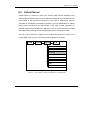
4.7 Multihoming
Figure 4.11 The Location of “Service / Multihoming” on the Menu Bar
BR-6641’s auto-routing service is a trunking technology that provides load balancing
and fault tolerance for all outbound requests. But it does not apply to inbound
requests. Based on a unique technology called SwiftDNSTM, BR-6641 offers a
Multihoming service for load balancing and fault tolerance for inbound requests. The
minimum requirement for Multihoming is that you must have multiple WAN links and
registered domain names for your publicly accessible servers. Whenever BR-6641
receives a DNS query; it answers the DNS query with a public IP address assigned
to one of the WAN links according to the settings of your answering policies.
Therefore, subsequent requests to your server will be sent the public IP of the WAN
link based on BR-6641’s previous response. You can configure your answering
policies with a weight for each WAN link so that the public IPs returned will be
distributed evenly by weight. If one of your WAN links fails, BR-6641 will not return
the public IP assigned to that failed link nevertheless your publicly accessible servers
70
BR-6641 User Manual
are still reachable via other live WAN links.
In order to let your Multihoming function properly, you must make sure that the
requirements listed below are met.
Prerequisites for Multihoming:
Multiple WAN links (at least two).
Registered domain names for your publicly accessible servers.
Your publicly accessible servers must be configured as virtual servers, or have public
IP addresses.
By default, Multihoming is switched off. To use this service, check the check box to
the right of “Enable Multihoming” on the top of the page. There are three tables for
configuring your Multihoming settings. The first table lets you define the global
parameters. The second table is used to configure your domain name settings.
Global Setting
Specify the PTR data in this field, including TTL, IP Address, and Host Name for
reverse looking up the host name of corresponding IP Address.
71
BR-6641 User Manual
Global Setting:
Field
Value
Description
TTL
<TTL>
Set DNS query response time.
IP Address
<IP Address>
Enter the reverse lookup IP address.
Host Name
<Link Number>
Enter the corresponding FQDN to the reverse IP.
Table 4.8 The Description of the Fields in Multihoming Global Setting
Domain Setting
In this table, you should configure your domain settings, including your multihoming
domain names (can be more than one), the DNS servers for querying your domain
names, and the answering policy to apply a given prefix of the domain name.
72
BR-6641 User Manual
Figure 4.12 Domain Setting
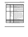
Domain Setting:
Field
Domain Name
Description
Enter the domain names for Multihoming.
additional domain names, press +.
To enter
TTL
Assign DNS query response time.
Responsible Mail
Enter the domain administrator’s email.
Primary Name Server
Enter the primary server name.
Source IP
The query IP address can be an IP address, IP range, subnet,
or any address.
NS Record
Name Server
Enter the prefix of the server name.
server’s
For example, if a
IP Address
Enter the IP address corresponding to the name server.
FQDN is nsl.abc.com, please enter “nsl”.
A Record
Host Name
Enter the prefix of the primary workstation’s name.
example, if the name is www.abc.com, enter “www”.
73
For
BR-6641 User Manual
Policy Type
The algorithm for selecting WAN links, by Wight or by Traffic.
By Weight: Answer DNS queries by the weight given to each
link.
By Total Traffic: Answer DNS queries by selecting the WAN
link with the lightest total traffic.
Parameter-IP
Enter the IP address to answer DNS queries.
Parameter-Weight
Input the weight for each WAN Link.
CName Record
Alias
Enter the alias of the domain name. For example, if you
wish to use www1.abc.com as the alias of www.abc.com,
(domain name), enter “www1” in this field.
Target
Enter the real domain name. For example, if you wish to use
www1.abc.com as the alias for www.abc.com, enter “www”.
MX Record
Host Name
Enter the prefix of the mail server’s domain name. For
example, if the domain name is mail.abc.com, enter “mail”.
Priority
Enter the priority of the mail servers.
The higher the priority,
the lower the number
Mail Server
Enter the IP address of the mail server.
Table 4.9
The Description of the Fields in Domain Setting
74
BR-6641 User Manual
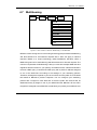
4.8 Internal DNS
Figure 4.13 The Location of “Service / Internal DNS” on the Menu Bar
BR-6641 has a built-in DNS server function which can be activated by completing
the fields in this page.
Global Settings:
Field
Enable InternalDNS
Value
Turn on/off internal DNS server.
PTR Record
TTL
Set DNS query response time.
IP Address
Enter the reverse lookup IP address.
Host Name
Enter the corresponding FQDN to the reverse IP.
Table 4.10 The Description of the Fields in Global Setting
75
BR-6641 User Manual
Domain Settings:
Field
Description
Domain Name
Enter the domain names for internal DNS.
additional domain names, press +.
To enter
TTL
Assign DNS query response time.
Responsible Mail
Enter the domain administrator’s email.
Primary Name Server
Enter the primary server name.
IP Address
The query IP address can be an IP address, IP range, subnet,
or any address.
NS Record
Name Server
Enter the prefix of the server name.
server’s
IP Address
Enter the IP address.
For example, if a
FQDN is nsl.abc.com, please enter “nsl”.
A Record
Host Name
Enter the prefix of the primary workstation’s name.
example, if the name is www.abc.com, enter “www”.
IP Address
Input the IP Address of Localhost.
For
Cname Record
Alias
Enter the alias of the domain name. For example, if you
wish to use www1.abc.com as the alias of www.abc.com,
(domain name), enter “www1” in this field.
Target
Enter the real domain name. For example, if you wish to use
www1.abc.com as the alias for www.abc.com, enter “www”.
MX Record
Host Name
Enter the prefix of the mail server’s domain name. For
example, if the domain name is mail.abc.com, enter “mail”.
Priority
Enter the priority of the mail servers.
the lower the number.
Mail Server
Enter the IP address of the mail server.
Table 4.11
The higher the priority,
The Description of the Fields in Domain Setting
76
BR-6641 User Manual
4.9 SNMP
Figure 4.14
The Location of “Service /SNMP” on the Menu Bar
SNMP (Simple Network Management Protocol) can be used to manage networks by
providing statistical data regarding network performance and security. It is often
used in the management of TCP/IP networks.
SNMP Settings:
Field
Description
Enable SNMP
Enable/Disable SNMP.
Community
Enter the community which the SNMP belongs to. The default
value is “public”.
Description
Enter the description of the machine.
Contact Info
Enter the contact information of the machine.
Node Name
Enter the Node Name.
Location
Enter the location of the machine.
Table 4.12
The Description of the Fields in SNMP
77
BR-6641 User Manual
4.10 UPnP
Figure 4.15
The Location of “Service / UPnP” on the Menu Bar
BR-6641 will detect the public UPnP (Universal Plug and Play) equipment in the
network and automatically respond to its predefined IP Address.
Field
Enable UPnP
Value
Enable
Description
Enable or disable the function.
Disable
WAN IP
<IP Address>
Input the WAN IP preserved for public UPnP, including dynamic
IP address and open IP address.
Weight
E.g.:1,2…
Input the weight, the bigger number will be given the higher
priority.
Table 4.13 The Description of the Fields in UPnP
78
BR-6641 User Manual
Chapter 5
Log
In this Chapter, you can control BR-6641’s logging activities with repect to various
functionalities such as the System, Firewall, Routing, etc. Administrator can also
either set up the log transmission methods to another server for purpose of archiving
and further analyses, or control the event notifications settings via emails.
Figure 5.1
The Location of Log and its Function on the Menu Bar
79
BR-6641 User Manual
5.1 View
In the ‘View’ Sub-menu, BR-6641 provides two types of comprehensive log records
(see the table below). Administrator can pick the desired log type and the
corresponding events for that type will be shown in the windows below. Press the
‘refresh’ button to get a copy of the latest log.
For log data pushing and archiving, see the ‘control’ sub-menu in next section. An
FTP Server or Email Server or Syslog Server should be provided.
Figure 5.2
Field
Log Type
The Location of Log/View Page Menu Bar
Value
Description
System Log
You can pick the log type of
your preferred events to be
shown in the log viewing
window.
Traffic Log
Recent Event
-
Event log listed by order of
timestamp
Refresh
-
Refresh to get the latest
event log
Table 5.1 The Description of the Fields on Log/View Page
80
BR-6641 User Manual
5.2 Control
With this sub-menu, you can set up how log data will be transmitted to other servers
(out of BR-6641) for archiving and further analyses. Transmission methods include
FTP, Email and Syslog. Each log type can have its own transmission method setting.
Figure 5.3
Location of Log/Control Page on the Menu Bar
Field
Value
Log Control
System Log
Description
Traffic Log
Select the type of Log file to
be pushed.
E-Mail
See below.
System Log
Log Method
FTP
Syslog
Push Now
Use this button to start log
pushing immediately.
Traffic Log
Log Method
E-Mail
See below.
FTP
Syslog
Push Now
Use this button to start log
pushing immediately.
Table 5.2
The Description of the Fields on Log/Control Page
81
BR-6641 User Manual
Method
BR-6641 offers three types of log transmissions: FTP out to an external FTP server,
Syslog out to a syslog server or send emails via SMTP to the administrator’s mailbox.
E-mail
Field
Value
Description
SMTP Server
<IP> or <Domain Name>
SMTP server for the logs.
Account
<SMTP Account>
Authenticated account for mail
server
Password
<Account’s Password>
Authenticated password for mail
server.
Mail From
<e-Mail address>
Sender of the Email.
Mail To
<e-Mail address>
Receiver of the Email.
Auto Push
Push this button to start log
pushing automaticaly.
Scheduled Push
Turn on scheduled push.
Initial Time
<Year/Month/Day/Hour/Minute/Second>
Start time for the scheduled push.
Period
<Day/Hour/Minute>
Scheduled push duration.
Table 5.3
Method: E-mail
82
BR-6641 User Manual
FTP
Field
Value
Description
Server
<IP> or <Domain Name>
FTP Server’s
domain name.
Account
<FTP Account>
FTP user account.
Password
<Account’s Password>
FTP user password.
Path
<Path>
FTP server path.
Auto Push
IP
Push this button to start
log
pushing
automatically.
Scheduled Push
Turn on scheduled push.
Initial Time
<Year/Month/Day/Hour/Minute/Second>
Start
time
for
scheduled push.
Period
<Day/Hour/Minute>
Scheduled
duration.
Table 5.4
or
the
push
Method: FTP
Syslog
Field
Syslog Server
Value
<IP> or <Domain Name>
Table 5.5
Method: Syslog
83
Description
Syslog Server’s IP or domain
name.
BR-6641 User Manual
5.3 Notification
In this sub-menu, you can set up how email notifications are sent out for important
system events. The setup is similar to previous section’s email account settings.
Figure 5.4
Location of Log/Notification Page on the Menu Bar
Notification
Field
Value
SNMP
Description
Select
how
Email
notifications are sent out.
Email
SNMP Settings
Destination IP
<IP Address>
The SNMP managing device
IP.
Community Name
<Community Name>
The community name.
Link Fail
Enable this function, system
will notify administrator when
a Link Fail happened.
Email Settings
SMTP Server
SMTP Server.
Account
Authenticated
mail server.
Password
Authenticated password for
mail server.
Mail From
Sender.
Mail To
Receiver.
84
account
for
BR-6641 User Manual
Link Fail
Enable this function, system
will notify administrator when
a Link Fail happened.
Admin Password Change
Enable this function, system
will notify administrator when
Administrator password is
changed.
Table 5.6
The Description of the Fields on Log/Notification
85