1
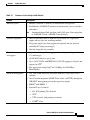
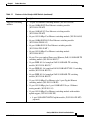
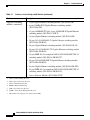
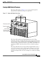
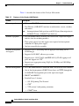
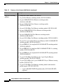
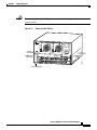
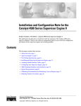
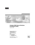
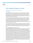
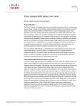
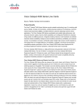
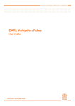
C H A P T E R
1
Product Overview
This chapter provides an overview of the features and components of the
Catalyst 4000 series switches and contains these sections:
•
Switch Features, page 1-1
•
Switch Components, page 1-12
Switch Features
The following sections describe the features of the Catalyst 4000 series switches:
•
Catalyst 4003 Switch Features, page 1-1
•
Catalyst 4006 Switch Features, page 1-7
Catalyst 4003 Switch Features
The Catalyst 4003 switch (see Figure 1-1) is a three-slot switch designed for
high-performance, high-density wiring closet applications.
Catalyst 4000 Series Switch Installation Guide
78-6120-10
1-1
Chapter 1
Product Overview
Switch Features
Figure 1-1
Catalyst 4003 Switch (Front View)
Redundant power supplies
Power Supply 1
Supervisor
engine
(slot 1)
CAUTION
Power Supply 2
THIS ASSEMBLY
CONTAINS
ELECTROSTATICSENSITIVE DEVICES
0%
100%
Switching
modules
(slots 2 and 3)
1
13
26216
1
13
Fan assembly
The Catalyst 4003 switch has a Gigabit Ethernet port and a 12-Gbps nonblocking,
full-duplex switching fabric that provides connections between the supervisor
engine and the switching modules. The Catalyst 4003 switch supports the
Supervisor Engine I. The Supervisor Engine I has a 10BASE-T Ethernet
management port (RJ-45 connector) and a console port (DCE DB-25 connector).
The Catalyst 4003 chassis has three slots for online-swappable modules. Slot 1 is
reserved for the supervisor engine, which provides switching, local and remote
management, and switch-status monitoring. Slots 2 and 3 are available for
switching modules.
Table 1-1 describes the features of the Catalyst 4003 switch.
Catalyst 4000 Series Switch Installation Guide
1-2
78-6120-10
Chapter 1
Product Overview
Switch Features
Table 1-1
Features of the Catalyst 4003 Switch
Feature
Ethernet speeds
Description
•
Ethernet (10BASE-T) interface to workstations and repeaters
•
Fast Ethernet (100BASE-T) interface to workstations, servers, switches,
and routers
Note
Standard equipment
Standard management
and support
Software management
Autonegotiation of link speed on each 10/100 port allows migration
to 100BASE-T from a 10BASE-T installed base.
•
Three-slot modular chassis with one slot reserved for a supervisor
engine and two slots for switching modules
•
Two power supply bays that support one required and one optional
redundant AC-input power supply
•
One hot-swappable fan assembly
•
Layer 2 forwarding with an aggregate forwarding rate of greater than
17.8 million pps
•
16,000 MAC addresses per system
•
Up to 1,024 VLANs with IEEE 802.1Q VLAN tagging on all ports and
support for VTP1
•
Port aggregation using PAgP2 for 100-Mbps and 1000-Mbps
EtherChannel
•
CLI3 and SNMP interfaces consistent with the Catalyst 6500 series
switches
•
Out-of-band management (SNMP, Telnet client, and TFTP) through the
10BASE-T management port on the supervisor engine
•
RMON4 with RMON 1
•
Standard Layer 2 features:
– 802.1D Spanning Tree Protocol
– CDP5
– VTP version 2 with pruning extensions
– CGMP6 client
Catalyst 4000 Series Switch Installation Guide
78-6120-10
1-3
Chapter 1
Product Overview
Switch Features
Table 1-1
Features of the Catalyst 4003 Switch (continued)
Feature
Description
Embedded management
Power supplies
Supervisor engine
•
Full SNMP implementation, including entity-MIB, all relevant standard
MIBs, and all relevant Cisco MIBs
•
The first four RMON groups (Ethernet statistics, Alarms, Events, and
History supported) on a per-port basis without an optional RMON
processing module
•
SPAN, allowing redirection of traffic from any port or VLAN to a SPAN
destination port
•
Performance management information
•
One standard 400 W, 12 V output, hot-swappable, load-sharing
redundant power supplies with AC power factor correction
•
Optional 400 W, 12 V output DC power supplies
•
Optional 650 W, 12 V output DC power supplies
•
PoE is not supported on the Catalyst 4003
•
Supports the Supervisor Engine I (WS-X4012)
•
Data path and control for all network interfaces with Ethernet
management and console ports
•
Interface monitoring, environmental status, and SNMP and
console/Telnet interface
Note
•
Packets are not forwarded while the supervisor engine is removed; a
system reboot occurs when a supervisor engine is reinserted.
Gigabit Ethernet (1000BASE-X) interface for backbone interconnection
of high-performance switches and routers
Catalyst 4000 Series Switch Installation Guide
1-4
78-6120-10
Chapter 1
Product Overview
Switch Features
Table 1-1
Features of the Catalyst 4003 Switch (continued)
Feature
Supported switching
modules
Description
•
24-port Fast Ethernet switching module (WS-X4124-RJ45)
•
24-port 100BASE-FX Fast Ethernet switching module
(WS-X4124-FX-MT)
•
48-port 100BASE-FX Fast Ethernet switching module
(WS-X4148-FX-MT)
•
48-port 10/100-Mbps Fast Ethernet switching module (WS-X4148-RJ)
•
48-port 100BASE-BX10-D Fast Ethernet switching module
(WS-X4148-FE-BD-LC)
•
48-port 100BASE-LX10 Fast Ethernet switching module
(WS-X4148-FE-LX-MT )
•
48-port 10/100-Mbps Fast Ethernet switching module
(WS-X4148-RJ21)
•
48-port Cisco prestandard Power over Ethernet (PoE) 10/100BASE-TX
switching module (WS-X4148-RJ45V)7
•
24-port IEEE 802.3af-compliant PoE 10/100BASE-TX switching
module (WS-X4224-RJ45V)7
•
48-port IEEE 802.3af-compliant PoE 10/100BASE-TX RJ-21 switching
module (WS-X4248-RJ21V)7
•
48-port IEEE 802.3af-compliant PoE 10/100BASE-TX switching
module (WS-X4248-RJ45V)7
•
32-port 10/100-Mbps Fast Ethernet plus 2-port Gigabit Ethernet
switching module (WS-X4232-GB-RJ)
•
32-port 10/100-Mbps plus 2-port 1000BASE-X Layer 3 Ethernet
routing module (WS-X4232-L3)
•
32-port 10/100-Mbps Fast Ethernet switching module with modular
uplink support (WS-X4232-RJ-XX)
– 4-port 100BASE-FX MT-RJ uplink module (WS-X4504-FX-MT)
(optional)
Catalyst 4000 Series Switch Installation Guide
78-6120-10
1-5
Chapter 1
Product Overview
Switch Features
Table 1-1
Features of the Catalyst 4003 Switch (continued)
Feature
Description
Supported switching
modules (continued)
•
2-port Gigabit Ethernet switching module (WS-X4302-GB)
•
6-port 1000BASE-X Gigabit Ethernet switching module
(WS-X4306-GB)
•
12-port 1000BASE-TX plus 2-port 1000BASE-X Gigabit Ethernet
switching module (WS-X4412-2GB-T)
•
18-port Gigabit Ethernet switching module (WS-X4418-GB)
•
24-port 10/100/1000BASE-T Gigabit Ethernet switching module
(WS-X4424-GB-RJ45)
•
48-port Gigabit Ethernet switching module (WS-X4448-GB-LX)
•
48-port 10/100/1000BASE-TX Gigabit Ethernet switching module
(WS-X4448-GB-RJ45)
•
24-port IEEE 802.3af-compliant PoE 10/100/1000 BASE-T RJ-45
switching module (WS-X4524-GB-RJ45V)7
•
48-port 10/100/1000BASE-T Gigabit Ethernet switching module
(WS-X4548-GB-RJ45)
•
48-port Gigabit Ethernet switching module (WS-X4448-GB-SFP)
•
48-port IEEE 802.3af-compliant PoE 10/100/1000 BASE-T RJ-45
switching module (WS-X4548-GB-RJ45V)7
•
Access Gateway Module (WS-X4604-GWY)
1. VTP = VLAN Trunking Protocol
2. PAgP = Port Aggregation Protocol
3. CLI = command-line interface
4. RMON = Remote Monitoring
5. CDP = Cisco Discovery Protocol
6. CGMP = Cisco Group Management Protocol
7. This module only supports data on the Catalyst 4003.
Catalyst 4000 Series Switch Installation Guide
1-6
78-6120-10
Chapter 1
Product Overview
Switch Features
Catalyst 4006 Switch Features
The Catalyst 4006 switch (see Figure 1-2) is a six-slot switch designed for
high-performance, high-density wiring closet applications.
Figure 1-2
Catalyst 4006 Switch (Front View)
Power supplies
Power
Supply
1
Power
Supply
2
Power
Supply
3
Power entry module
CAUTIO
N
Supervisor engine
(slot 1)
THIS ASSEM
BLY
CONTA
INS
ELECTR
OSTATI
SENSIT
CIVE DEVICE
S
UPLINK
UPLINK
STATUS
1
2
UPLINKS
ENABLED
Fan assembly
CONSO
LE
10/100
BASE-T
X
RESET
1%
100%
Switching modules
(slots 2 through 6)
1
1
13
1
13
1
13
31334
1
13
1
13
13
The Catalyst 4006 switch has two Gigabit Ethernet ports and a 32-Gbps,
nonblocking, full-duplex switching fabric that provides connections between the
supervisor engine and the switching modules. The Gigabit Ethernet ports can be
configured with any combination of shortwave SX, LX/LH, and ZX GBICs. For
a description of GBICs, refer to the Catalyst 4500 Series Module Installation
Guide.
The Catalyst 4006 chassis has six slots for online-swappable modules. Slot 1 is
reserved for the supervisor engine, which provides switching, local and remote
management, and switch-status monitoring. The Catalyst 4006 switch supports
the Supervisor Engine II, III, or IV. Slots 2 through 6 are available for switching
modules.
Catalyst 4000 Series Switch Installation Guide
78-6120-10
1-7
Chapter 1
Product Overview
Switch Features
Table 1-2 describes the features of the Catalyst 4006 switch.
Table 1-2
Features of the Catalyst 4006 Switch
Feature
Description
Ethernet speeds
•
Ethernet (10BASE-T) interface to workstations and repeaters
•
Fast Ethernet (100BASE-T) interface to workstations, servers, switches,
and routers
Note
Standard equipment
Standard management
and support
Software management
Autonegotiation of link speed on each 10/100 port allows migration to
100BASE-T from a 10BASE-T installed base.
•
Six-slot modular chassis with one slot reserved for a supervisor engine
and five slots for switching modules
•
Three power supply bays that support two required and one optional
redundant AC-input power supply
•
One hot-swappable fan assembly
•
Supports Layer 2 forwarding with an aggregate forwarding rate of
18 million pps
•
Supports 16,000 MAC addresses per system
•
Supports up to 1,024 VLANs with IEEE 802.1Q VLAN tagging on all
ports and support for VTP1
•
Supports port aggregation using PAgP2 for 100-Mbps and 1000-Mbps
EtherChannel
•
CLI3 and SNMP interfaces consistent with Catalyst 6500 series switches
•
Out-of-band management (SNMP, Telnet client, and TFTP) through the
10/100BASE-T management port on the supervisor engine
•
RMON4 with RMON 1
•
Standard Layer 2 features:
– 802.1D Spanning Tree Protocol
– CDP5
– VTP version 2 with pruning extensions
– CGMP6 client
Catalyst 4000 Series Switch Installation Guide
1-8
78-6120-10
Chapter 1
Product Overview
Switch Features
Table 1-2
Features of the Catalyst 4006 Switch (continued)
Feature
Embedded
management
Power supplies
Supervisor engine
Description
•
Full SNMP implementation, including entity-MIB, all relevant standard
MIBs, and all relevant Cisco MIBs
•
The first four RMON groups (Ethernet statistics, Alarms, Events, and
History) on a per-port basis without an optional RMON processing
module
•
SPAN, allowing you to redirect traffic from any port or VLAN to a SPAN
destination port
•
Performance management information
•
Three 400 W, 12 V output, hot-swappable, load-sharing power supplies
with AC power factor correctionOptional 400 W, 12 V output DC power
supplies
•
Optional 650 W, 12 V output DC power supplies
•
Supports the Supervisor Engine II (WS-X4013), Supervisor Engine III
(WS-X4014), and Supervisor Engine IV (WS-X4515)
•
Data path and control for all network interfaces with Ethernet
management and console ports
•
Interface monitoring, environmental status, and SNMP and
console/Telnet interface
Note
Packets are not forwarded while the supervisor engine is removed; a
system reboot occurs when a supervisor engine is reinserted.
•
32-port full-duplex Gigabit Ethernet switching engine
•
Two Gigabit Ethernet (1000BASE-X) interfaces for backbone
interconnection of high-performance switches and routers
Catalyst 4000 Series Switch Installation Guide
78-6120-10
1-9
Chapter 1
Product Overview
Switch Features
Table 1-2
Features of the Catalyst 4006 Switch (continued)
Feature
Description
Supported switching
modules
•
Backplane channel module (WS-X4019)
•
24-port Fast Ethernet switching module (WS-X4124-RJ45)
•
24-port 100BASE-FX Fast Ethernet switching module
(WS-X4124-FX-MT)
•
48-port 100BASE-FX Fast Ethernet switching module
(WS-X4148-FX-MT)
•
48-port 10/100-Mbps Fast Ethernet switching module (WS-X4148-RJ)
•
48-port 100BASE-BX10-D Fast Ethernet switching module
(WS-X4148-FE-BD-LC)
•
48-port 100BASE-LX10 Fast Ethernet switching module
(WS-X4148-FE-LX-MT )
•
48-port 10/100-Mbps Fast Ethernet switching module (WS-X4148-RJ21)
•
48-port Cisco pre-standard Power over Ethernet (PoE) 10/100BASE-TX
switching module (WS-X4148-RJ45V)
•
24-port IEEE 802.3af-compliant PoE 10/100BASE-TX switching module
(WS-X4224-RJ45V)
•
48-port IEEE 802.3af-compliant PoE 10/100BASE-TX RJ-21 switching
module (WS-X4248-RJ21V)
•
48-port IEEE 802.3af-compliant PoE 10/100BASE-TX switching module
(WS-X4248-RJ45V)
•
32-port 10/100-Mbps Fast Ethernet plus 2-port Gigabit Ethernet
switching module (WS-X4232-GB-RJ)
•
32-port 10/100-Mbps plus 2-port 1000BASE-X Layer 3 Ethernet routing
module (WS-X4232-L3)
•
32-port 10/100-Mbps Fast Ethernet switching module with modular
uplink support (WS-X4232-RJ-XX)
– 4-port 100BASE-FX MT-RJ uplink module (WS-X4504-FX-MT)
(optional)
Catalyst 4000 Series Switch Installation Guide
1-10
78-6120-10
Chapter 1
Product Overview
Switch Features
Table 1-2
Features of the Catalyst 4006 Switch (continued)
Feature
Supported switching
modules (continued)
Description
•
2-port Gigabit Ethernet switching module (WS-X4302-GB)
•
6-port 1000BASE-X Gigabit Ethernet switching module
(WS-X4306-GB)
•
12-port 1000BASE-TX plus 2-port 1000BASE-X Gigabit Ethernet
switching module (WS-X4412-2GB-T)
•
18-port Gigabit Ethernet switching module (WS-X4418-GB)
•
24-port 10/100/1000BASE-T Gigabit Ethernet switching module
(WS-X4424-GB-RJ45)
•
48-port Gigabit Ethernet switching module (WS-X4448-GB-LX)
•
48-port 10/100/1000BASE-TX Gigabit Ethernet switching module
(WS-X4448-GB-RJ45)
•
24-port IEEE 802.3af-compliant PoE 10/100/1000 BASE-T RJ-45
switching module (WS-X4524-GB-RJ45V)
•
48-port 10/100/1000BASE-T Gigabit Ethernet switching module
(WS-X4548-GB-RJ45)
•
48-port Gigabit Ethernet switching module (WS-X4448-GB-SFP)
•
48-port IEEE 802.3af-compliant PoE 10/100/1000 BASE-T RJ-45
switching module (WS-X4548-GB-RJ45V)
•
Access Gateway Module (WS-X4604-GWY)
1. VTP = VLAN Trunking Protocol
2. PAgP = Port Aggregation Protocol
3. CLI = command-line interface
4. RMON = Remote Monitoring
5. CDP = Cisco Discovery Protocol
6. CGMP = Cisco Group Management Protocol
Catalyst 4000 Series Switch Installation Guide
78-6120-10
1-11
Chapter 1
Product Overview
Switch Components
Switch Components
The following components are standard on the Catalyst 4003 switch:
•
Fan assembly: fan tray and two fans
•
One Supervisor Engine I
•
One AC-input power supply
The following components are available as options for the Catalyst 4003 switch:
•
One additional AC-input power supply for redundancy
•
Up to two switching modules
•
One or more DC-input power supplies for redundancy
The following components are standard on the Catalyst 4006 switch:
•
Fan assembly: fan tray and four fans
•
One Supervisor Engine II
•
Two AC-input power supplies
The following components are available as options for the Catalyst 4006 switch:
•
One additional AC-input power supply for redundancy
•
Up to five switching modules
•
One or more DC-input power supplies for redundancy
Fan Assembly
Note
For complete environmental specifications, including airflow requirements, see
Appendix A, “Specifications.”
The system fan assembly provides cooling air for the internal chassis components.
The fan assembly is a tray of fans that you can insert and remove from the chassis
while the system is on line. The Catalyst 4003 switch fan assembly has two fans,
and the Catalyst 4006 switch has four fans. The fans exhaust air from one side and
draw in fresh air on the other side. Catalyst 4003 switch airflow is shown in
Figure 1-3. Catalyst 4006 switch airflow is shown in Figure 1-4.
Catalyst 4000 Series Switch Installation Guide
1-12
78-6120-10
Chapter 1
Product Overview
Switch Components
Caution
You must install module filler plates on unused switching module slots to ensure
proper airflow.
Figure 1-3
Catalyst 4003 Airflow
CAUTION
THIS ASSEMBLY
CONTAINS
ELECTROSTATICSENSITIVE DEVICES
0%
100%
1
13
16668
1
13
Fan assembly
Catalyst 4000 Series Switch Installation Guide
78-6120-10
1-13
Chapter 1
Product Overview
Switch Components
Figure 1-4
Catalyst 4006 Airflow
Power
Supply
1
Power
Supply
2
Power
CAUTIO
N
Supply
3
THIS ASSEM
BLY
CONTA
INS
ELECTR
OSTATI
SENSIT
CIVE DEVICE
S
UPLINK
UPLINK
STATUS
1
2
UPLINKS
ENABLED
CONSO
LE
10/100
BASE-T
X
RESET
1%
100%
1
1
13
1
13
1
1
13
1
13
Fan assembly
28843
13
13
If one fan on the tray fails, the other fans continue to run. A sensor on the
supervisor engine monitors internal air temperature. If the air temperature
exceeds a specified threshold, the environmental monitor displays warning
messages. Threshold and status level descriptions are provided in the “Power
Supplies” section.
To replace a fan assembly, see Chapter 4, “Removing and Replacing FRUs.”
Note
For complete power specifications, see Appendix A, “Specifications.”
Catalyst 4000 Series Switch Installation Guide
1-14
78-6120-10
Chapter 1
Product Overview
Switch Components
Power Supplies
The Catalyst 4000 series switches can use a 400 W AC-input power supply (see
Figure 1-5), a 400 W DC-input power supply (see Figure 1-6), or a 650 W
DC-input power supply (see Figure 1-7). The AC-input power supply has a power
cord that connects each power supply to the site power source. The DC-input
power supplies are equipped with a compression-style input terminal block that is
directly connected to the site power wiring.
The power supply does not have a power switch. Power is provided when the
power cord and wiring are installed and plugged into an electrical outlet and the
unit is fully seated in the system chassis.
Figure 1-5
400 W AC-Input Power Supply
Captive screws
16674
GOOD
FAIL
100-240V~
6.3A
50-60Hz
580W
AC power connection
Catalyst 4000 Series Switch Installation Guide
78-6120-10
1-15
Chapter 1
Product Overview
Switch Components
Figure 1-6
400 W DC-Input Power Supply
Captive screws
38133
FASTNERS MUST BE FULLY ENGAGED
PRIOR TO OPERATING POWER
SUPPLY
48-60V~
11A
+
+
+
+
DC power connection
Figure 1-7
650 W DC-Input Power Supply
Captive screws
FASTNERS MUST BE FULLY ENGAGE
D
PRIOR TO OPERATING POWER
SUPPLY
GOOD
FAIL
68609
-48 -60V
18A
DC power connection
Catalyst 4000 series switches support redundant power supplies. Each power
supply has an individual power cord and status LEDs. The Catalyst 4003 switch
has one standard power supply and an optional redundant power supply. The
Catalyst 4000 Series Switch Installation Guide
1-16
78-6120-10
Chapter 1
Product Overview
Switch Components
Catalyst 4006 switch has two standard power supplies and one optional redundant
power supply. Two standard power supplies are required to operate a
Catalyst 4006 switch. Systems with three power supplies will share the load with
each unit providing approximately one-third of the total load.
When power is removed from one power supply on a Catalyst 4003 switch that
has two power supplies, the redundant power feature causes the second power
supply to produce full power.
When power is removed from one power supply on a Catalyst 4006 switch that
has three power supplies, the other two power supplies produce full power. Load
sharing returns when all three power supplies are on.
To replace a power supply, see the “Removing and Replacing the Power Supply”
section on page 4-2.
Power Supply LEDs
The AC power supply has two front-panel LEDs:
•
The LED labeled GOOD is green when the power supply is connected and
operating normally.
•
The LED labeled FAIL is red when there is a problem with the power supply.
Power Supply Fan
Each power supply has a built-in fan. Air enters the front of the power supply
(power-input end) and exits through the back. An air dam keeps the airflow
separate from the rest of the chassis, which is cooled by the system fan assembly.
Load-Sharing Feature
When you install and power-on a second power supply on a Catalyst 4003 switch,
it provides approximately half of the required power to the system. If one power
supply fails, the other power supply immediately assumes full power to maintain
uninterrupted system operation.
When you install and turn on a third power supply on a Catalyst 4006 switch, it
provides approximately one-third of the power required by the system. If one
power supply fails, the other two immediately generate full power to maintain
uninterrupted system operation.
Catalyst 4000 Series Switch Installation Guide
78-6120-10
1-17
Chapter 1
Product Overview
Switch Components
When you install a redundant power supply, load sharing and fault tolerance are
enabled automatically; no additional software configuration is required.
Environmental Monitoring Feature
With the environmental monitoring and reporting feature, you can keep your
system running by resolving adverse environmental conditions before loss of
operation. The power supply monitors its own internal temperature and voltages.
In the event of excessive internal temperature, the power supply shuts down to
prevent damage. When the power supply returns to a safe operating temperature,
it restarts. If the power supply output voltage is abnormal, the LED labeled
OUTPUT FAIL will light. An instance of substantial input overvoltage can shut
down the power supply.
The supervisor engine monitors the status of each power supply and provides a
status report through the switch software. For more information on how the
supervisor engine monitors the power supplies, refer to the Catalyst 4500 Series
Module Installation Guide.
External Power Shelf
The Catalyst 4006 external power shelf contains up to three single-phase, AC-DC,
1050 W, –52 V output power supplies, which can provide Power over Ethernet to
enabled switching modules when used with the power entry module.
Catalyst 4000 Series Switch Installation Guide
1-18
78-6120-10