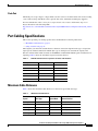
1
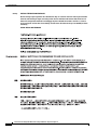
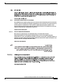
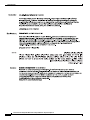
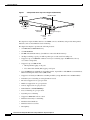
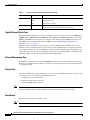
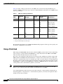
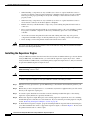
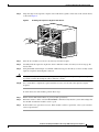
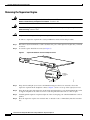
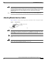
Installation and Configuration Note for the
Catalyst 4500 Series Supervisor Engine V
Product Numbers: WS-X4516 = Catalyst 4500 Series Supervisor Engine V
This publication describes how to install and verify the operation of the Catalyst 4500 series
Supervisor Engine V. Refer to the software configuration guide for your switch for configuration
information for the supervisor engines and switching modules.
Contents
This document contains these sections:
•
Safety Overview, page 2
•
Supervisor Engine V, page 7
•
Port Cabling Specifications, page 11
•
Installing and Removing the Supervisor Engine, page 13
•
Attaching Module Interface Cables, page 17
•
Configuring Your Supervisor Engine, page 18
•
GBIC Handling Guidelines and Installation, page 18
•
Related Documentation, page 21
•
OObtaining Documentation and Submitting a Service Request, page 21
•
Obtaining Technical Assistance, page 20
Corporate Headquarters:
Cisco Systems, Inc., 170 West Tasman Drive, San Jose, CA 95134-1706 USA
Copyright © 2004 Cisco Systems, Inc. All rights reserved.
Safety Overview
Safety Overview
Throughout this publication, safety warnings appear in procedures that can harm you if performed
incorrectly. A warning symbol precedes each warning statement.
Warning
IMPORTANT SAFETY INSTRUCTIONS
This warning symbol means danger. You are in a situation that could cause bodily injury. Before you
work on any equipment, be aware of the hazards involved with electrical circuitry and be familiar
with standard practices for preventing accidents. Use the statement number provided at the end of
each warning to locate its translation in the translated safety warnings that accompanied this
device. Statement 1071
SAVE THESE INSTRUCTIONS
Waarschuwing
BELANGRIJKE VEILIGHEIDSINSTRUCTIES
Dit waarschuwingssymbool betekent gevaar. U verkeert in een situatie die lichamelijk letsel kan
veroorzaken. Voordat u aan enige apparatuur gaat werken, dient u zich bewust te zijn van de bij
elektrische schakelingen betrokken risico's en dient u op de hoogte te zijn van de standaard
praktijken om ongelukken te voorkomen. Gebruik het nummer van de verklaring onderaan de
waarschuwing als u een vertaling van de waarschuwing die bij het apparaat wordt geleverd, wilt
raadplegen.
BEWAAR DEZE INSTRUCTIES
Varoitus
TÄRKEITÄ TURVALLISUUSOHJEITA
Tämä varoitusmerkki merkitsee vaaraa. Tilanne voi aiheuttaa ruumiillisia vammoja. Ennen kuin
käsittelet laitteistoa, huomioi sähköpiirien käsittelemiseen liittyvät riskit ja tutustu
onnettomuuksien yleisiin ehkäisytapoihin. Turvallisuusvaroitusten käännökset löytyvät laitteen
mukana toimitettujen käännettyjen turvallisuusvaroitusten joukosta varoitusten lopussa näkyvien
lausuntonumeroiden avulla.
SÄILYTÄ NÄMÄ OHJEET
Attention
IMPORTANTES INFORMATIONS DE SÉCURITÉ
Ce symbole d'avertissement indique un danger. Vous vous trouvez dans une situation pouvant
entraîner des blessures ou des dommages corporels. Avant de travailler sur un équipement, soyez
conscient des dangers liés aux circuits électriques et familiarisez-vous avec les procédures
couramment utilisées pour éviter les accidents. Pour prendre connaissance des traductions des
avertissements figurant dans les consignes de sécurité traduites qui accompagnent cet appareil,
référez-vous au numéro de l'instruction situé à la fin de chaque avertissement.
CONSERVEZ CES INFORMATIONS
Installation and Configuration Note for the Catalyst 4500 Series Supervisor Engine V
2
78-15590-02
Safety Overview
Warnung
WICHTIGE SICHERHEITSHINWEISE
Dieses Warnsymbol bedeutet Gefahr. Sie befinden sich in einer Situation, die zu Verletzungen führen
kann. Machen Sie sich vor der Arbeit mit Geräten mit den Gefahren elektrischer Schaltungen und
den üblichen Verfahren zur Vorbeugung vor Unfällen vertraut. Suchen Sie mit der am Ende jeder
Warnung angegebenen Anweisungsnummer nach der jeweiligen Übersetzung in den übersetzten
Sicherheitshinweisen, die zusammen mit diesem Gerät ausgeliefert wurden.
BEWAHREN SIE DIESE HINWEISE GUT AUF.
Avvertenza
IMPORTANTI ISTRUZIONI SULLA SICUREZZA
Questo simbolo di avvertenza indica un pericolo. La situazione potrebbe causare infortuni alle
persone. Prima di intervenire su qualsiasi apparecchiatura, occorre essere al corrente dei pericoli
relativi ai circuiti elettrici e conoscere le procedure standard per la prevenzione di incidenti.
Utilizzare il numero di istruzione presente alla fine di ciascuna avvertenza per individuare le
traduzioni delle avvertenze riportate in questo documento.
CONSERVARE QUESTE ISTRUZIONI
Advarsel
VIKTIGE SIKKERHETSINSTRUKSJONER
Dette advarselssymbolet betyr fare. Du er i en situasjon som kan føre til skade på person. Før du
begynner å arbeide med noe av utstyret, må du være oppmerksom på farene forbundet med
elektriske kretser, og kjenne til standardprosedyrer for å forhindre ulykker. Bruk nummeret i slutten
av hver advarsel for å finne oversettelsen i de oversatte sikkerhetsadvarslene som fulgte med denne
enheten.
TA VARE PÅ DISSE INSTRUKSJONENE
Aviso
INSTRUÇÕES IMPORTANTES DE SEGURANÇA
Este símbolo de aviso significa perigo. Você está em uma situação que poderá ser causadora de
lesões corporais. Antes de iniciar a utilização de qualquer equipamento, tenha conhecimento dos
perigos envolvidos no manuseio de circuitos elétricos e familiarize-se com as práticas habituais de
prevenção de acidentes. Utilize o número da instrução fornecido ao final de cada aviso para
localizar sua tradução nos avisos de segurança traduzidos que acompanham este dispositivo.
GUARDE ESTAS INSTRUÇÕES
¡Advertencia!
INSTRUCCIONES IMPORTANTES DE SEGURIDAD
Este símbolo de aviso indica peligro. Existe riesgo para su integridad física. Antes de manipular
cualquier equipo, considere los riesgos de la corriente eléctrica y familiarícese con los
procedimientos estándar de prevención de accidentes. Al final de cada advertencia encontrará el
número que le ayudará a encontrar el texto traducido en el apartado de traducciones que acompaña
a este dispositivo.
GUARDE ESTAS INSTRUCCIONES
Installation and Configuration Note for the Catalyst 4500 Series Supervisor Engine V
78-15590-02
3
Safety Overview
Varning!
VIKTIGA SÄKERHETSANVISNINGAR
Denna varningssignal signalerar fara. Du befinner dig i en situation som kan leda till personskada.
Innan du utför arbete på någon utrustning måste du vara medveten om farorna med elkretsar och
känna till vanliga förfaranden för att förebygga olyckor. Använd det nummer som finns i slutet av
varje varning för att hitta dess översättning i de översatta säkerhetsvarningar som medföljer denna
anordning.
SPARA DESSA ANVISNINGAR
Installation and Configuration Note for the Catalyst 4500 Series Supervisor Engine V
4
78-15590-02
Safety Overview
Aviso
INSTRUÇÕES IMPORTANTES DE SEGURANÇA
Este símbolo de aviso significa perigo. Você se encontra em uma situação em que há risco de lesões
corporais. Antes de trabalhar com qualquer equipamento, esteja ciente dos riscos que envolvem os
circuitos elétricos e familiarize-se com as práticas padrão de prevenção de acidentes. Use o
número da declaração fornecido ao final de cada aviso para localizar sua tradução nos avisos de
segurança traduzidos que acompanham o dispositivo.
GUARDE ESTAS INSTRUÇÕES
Advarsel
VIGTIGE SIKKERHEDSANVISNINGER
Dette advarselssymbol betyder fare. Du befinder dig i en situation med risiko for
legemesbeskadigelse. Før du begynder arbejde på udstyr, skal du være opmærksom på de
involverede risici, der er ved elektriske kredsløb, og du skal sætte dig ind i standardprocedurer til
undgåelse af ulykker. Brug erklæringsnummeret efter hver advarsel for at finde oversættelsen i de
oversatte advarsler, der fulgte med denne enhed.
GEM DISSE ANVISNINGER
Installation and Configuration Note for the Catalyst 4500 Series Supervisor Engine V
78-15590-02
5
Safety Overview
Installation and Configuration Note for the Catalyst 4500 Series Supervisor Engine V
6
78-15590-02
Supervisor Engine V
Supervisor Engine V
This section describes the Catalyst 4500 series Supervisor Engine V (WS-X4516). See Figure 1. This
supervisor engine provides data path and data control for all network interfaces.
The Supervisor Engine V is supported in the Catalyst 4006, 4503, 4506, 4507R, and 4510R switches.
On the Catalyst 4006, 4503, and 4506 switches, you can install the Supervisor Engine V only in slot 1.
On the Catalyst 4507R or 4510R switch, you install the primary supervisor engine in slot 1, and you can
install an optional redundant supervisor engine in slot 2.
The supervisor engine is hot swappable, but packets are not forwarded when the supervisor engine has
been removed from the switch. When a supervisor engine is reinserted into the switch, the system
reboots.
Installation and Configuration Note for the Catalyst 4500 Series Supervisor Engine V
78-15590-02
7
Supervisor Engine V
Figure 1
Catalyst 4500 Series Supervisor Engine V (WS-X4516)
RESET button
STATUS LED
WS-X45
15 SUP
ERVISO
R ENGINE
IV
UPLINK
1
UPLINK
2
STATUS
LINE ACT
IVE
LINE ACT
IVE
ACTIVE
UTILIZAT
FLASH
100%
Gigabit uplink
ports
EJECT
CONSOLE
10/100
MGT
RESET
LINK
77509
ION
1%
Switch load
indicators
Ethernet
management port
CONSOLE
Compact
port
Flash
port
The supervisor engine includes interfaces for SNMP, console, and Telnet, and provides management
functions, such as environmental status monitoring.
The Supervisor Engine V provides the following features:
•
512-MB Onboard SDRAM memory
•
512-KB NVRAM
•
64-MB onboard Flash memory (in addition to removable Flash memory)
•
96-Gbps switching capacity, 72 million packets-per-second actual forwarding rate
•
Support for up to 32,000 MAC addresses for Layer 2 switching (up to 64,000 entries, 16-way
associative lookup table)
•
Support for up to 4,000 VLANs
– 802.1Q VLAN tagging on all ports
– Cisco Inter Switch Link (ISL) tagging on all ports
•
Up to 64,000 unicast and multicast forwarding entries, expandable to 256, 000 unicast and multicast
IPV4 forwarding information base (FIB) entries
•
Support for all Catalyst 4500 series switching modules (except WS-X4232-L3 and WS-X4019)
•
Default Layer 2 forwarding at startup (hardware based)
•
Broadcast suppression on a per-port basis
•
Multicast suppression on a per-port basis
•
Unicast suppression on a per-port basis
•
EtherChannel at 10/100/1000 Mbps
•
Protocol filtering on a per-port basis
•
Dynamic protocol filtering
•
Support for IEEE 802.3x flow control
•
Hardware-based Layer 3 Switching
•
Hardware-based multicast
•
Hardware-based access lists
•
IP telephony
Installation and Configuration Note for the Catalyst 4500 Series Supervisor Engine V
8
78-15590-02
Supervisor Engine V
•
Supervisor engine redundancy between primary and standby supervisor engines in Catalyst 4510R
and Catalyst 4507R
•
802.1Q tunneling
•
Storm control in hardware
•
Support for the Catalyst 4500 Series NetFlow Services Card (WS-F4531).
When the Supervisor Engine V is used in a Catalyst 4510R, slot 10 is a flex-slot intended for use with
the 2-port Gigabit Ethernet switching module (WS-X4302-GB) or the Access Gateway Module
(WS-X4604-GWY) only.
Features of the Supervisor Engine Front Panel
The following sections describe the LEDs, connectors, and switches on the Catalyst 4500 series
Supervisor Engine V:
•
LEDs, page 9
•
Gigabit Ethernet Uplink Ports, page 10
•
Ethernet Management Port, page 10
•
Console Port, page 10
•
Reset Button, page 10
•
Flash Port, page 11
LEDs
Table 1 describes the LEDs on the supervisor engine front panel.
Table 1
Supervisor Engine LEDs (WS-X4516)
LED
LED Status
STATUS
UTILIZATION
Description
Indicates the results of a series of self-tests.
Green
All diagnostic tests passed.
Red
A test failed.
Orange
System boot or diagnostic test is in progress.
Off
Module is disabled.
Green 1–100%
If the switch is operational, this display indicates the current
traffic load over the backplane (as an approximate percentage).
Link
Indicates the status of the 10/100BASE-T Ethernet management
port or uplink ports.
Green
The link is operational.
Orange
The link is disabled by user.
Flashing orange
The power-on self-test indicates a faulty port.
Off
No signal is detected or there is a link configuration failure.
Installation and Configuration Note for the Catalyst 4500 Series Supervisor Engine V
78-15590-02
9
Supervisor Engine V
Table 1
Supervisor Engine LEDs (WS-X4516) (Continued)
LED
LED Status
Active
ACTIVE
Description
Indicates whether the uplink port is active.
Green
The port is active.
Off
The port is not active.
The LED to the right of the uplink ports is used to identify the
active supervisor in switches with two supervisors.
Gigabit Ethernet Uplink Ports
The Gigabit Ethernet uplink ports operate in full-duplex mode only. These ports use the 1000BASE-T,
1000BASE-SX, 1000BASE-LX/LH, 1000BASE-ZX, CWDM, and DWDM Gigabit Interface Converters
(GBICs). The GBICs have SC connectors to interface with multimode fiber (MMF) and single-mode
fiber (SMF) cable. For further information on GBICs, see the “GBIC Handling Guidelines and
Installation” section on page 18.
When two Supervisor Engine Vs are present in a Catalyst 4510R or Catalyst 4507R switch, all four
uplinks are active on both the primary (active) and secondary (standby) supervisor engines by default,
or two uplinks will be active in a nonredundant configuration. When using the Supervisor Engine V, slot
10 (the Flex-Slot) in the Catalyst 4510R switch supports the 2-port Gigabit Ethernet switching module
(WS-X4302-GB) or the Access Gateway Module (WS-X4604-GWY).
Ethernet Management Port
The Ethernet management port is used (in ROMMON mode only) to recover a switch software image
that has been corrupted or destroyed due to a network catastrophe. This port is not active while the switch
is operating normally.
Console Port
The Catalyst 4500 series Supervisor Engine V console port has an EIA/TIA-232 RJ-45 connector. The
console port allows you to perform the following functions:
Note
•
Configure the switch from the CLI
•
Monitor network statistics and errors
•
Configure SNMP agent parameters
EIA/TIA-232 was known as recommended standard RS-232 before its acceptance as a standard by the
Electronic Industries Alliance (EIA) and Telecommunications Industry Association (TIA).
Reset Button
The Reset button is used to restart the switch.
Note
Use a paper clip or other small, pointed object to press the Reset button.
Installation and Configuration Note for the Catalyst 4500 Series Supervisor Engine V
10
78-15590-02
Port Cabling Specifications
Flash Port
The Flash port accepts a Type 1 compact Flash card. You can use it for file transfer tasks such as loading
a new software image. The Flash card is optional and can be obtained from third-party suppliers.
For more information, refer to Using the Compact Flash on the Catalyst 4000 Family Supervisor
Engine III and IV at the following URL:
http://www.cisco.com/en/US/docs/switches/lan/catalyst4500/hardware/configuration/notes/OL_2788.h
tml
Port Cabling Specifications
This section provides port cabling specifications and includes the following subsections:
•
Maximum Cable Distances, page 11
•
Using a Patch Cord, page 12
The length of your networks and the distances between connections depend on the type of signal, the
signal speed, and the transmission medium (the type of cabling used to transmit the signals). The
distance and rate limits in this document are the IEEE-recommended maximum speeds and distances for
signaling. Table 2 shows the transmission speed versus the distance.
Table 2
EIA/TIA-232 Transmission Speed in Contrast with Distance
Rate (bps)
Distance (ft)
Distance (m)
2400
200
60
4800
100
30
9600
50
15
19,200
25
7.6
38,400
12
3.7
56,000
8.6
2.6
Maximum Cable Distances
Table 3 shows the maximum cable distances for transceiver speed and cable type.
Table 3
Maximum Cable Distances
Transceiver
Speed
Cable Type
Duplex Mode
Maximum Distance
Between Stations
10 Mbps
Category 3 UTP
Half or full
328 ft. (100 m)
10 Mbps
MMF
Half or full
1.2 mi. (2 km)
100 Mbps
Category 5 UTP
Half or full
328 ft. (100 m)
100 Mbps
MMF
Half
1312 ft. (400 m)
100 Mbps
MMF
Full
1.2 mi. (2 km)
Installation and Configuration Note for the Catalyst 4500 Series Supervisor Engine V
78-15590-02
11
Port Cabling Specifications
Table 4 provides cabling specifications for the GBICs that you install in the Gigabit Ethernet port
modules. All GBIC ports have SC-type connectors, and the minimum cable distance for all GBICs listed
is 6.5 feet (2 meters).
Table 4
GBIC Port Cabling Specifications
GBIC
Wavelength
(nm)
Fiber Type
Core Size
(micron)
Modal Bandwidth
(MHz/km)
Cable Distance
BASE-T
–
Category 5 UTP
–
–
328-ft (100m)
850
MMF
62.5
160
722 ft. (220 m)
62.5
200
902 ft. (275 m)
50.0
400
1640 ft. (500 m)
50.0
500
1804 ft. (550 m)
62.5
500
1804 ft. (550 m)
50.0
400
1804 ft. (550 m)
50.0
500
1804 ft. (550 m)
SMF
9/10
–
6.2 mi. (10 km)
SMF
9/10
–
43.5 mi. (70 km)
SMF3
9/10
SX
1
LX/LH
ZX
1300
1550
MMF
2
62.1 mi. (100 km)
1. MMF only.
2. Patch cord required (see the “Using a Patch Cord” section for details).
3. Dispersion-shifted single-mode fiber-optic.
The maximum cable distance for CWDM and DWDM cabling depends on fiber type, fiber quality, and
the number of WDM filters in the design.
Using a Patch Cord
When using the LX/LH GBIC with 62.5-micron diameter MMF, you must install a mode-conditioning
patch cord (Cisco product number CAB-GELX-625 or equivalent) between the GBIC and the MMF
cable on both the transmit and receive ends of the link.
The patch cord is required for link distances greater than 984 feet (300 meters) and must comply with
IEEE standards. The IEEE found that link distances could not be met with certain types of fiber-optic
cable due to a problem in the center of some fiber-optic cable cores. The solution is to launch light from
the laser at a precise offset from the center by using the patch cord. At the output of the patch cord, the
LX/LH GBIC is compliant with the IEEE 802.3z standard for 1000BASE-LX. For a detailed description
of this problem, refer to the installation guide for your switch.
Note
We do not recommend using the LX/LH GBIC with MMF without a patch cord for very short link
distances (tens of meters). The result could be an elevated bit error rate (BER).
Cisco Gigabit Ethernet products have been tested and evaluated to comply with the standards that are
listed in Appendix A, “Specifications,” of the installation guide for your switch. All equivalent cables
should also meet these standards.
Installation and Configuration Note for the Catalyst 4500 Series Supervisor Engine V
12
78-15590-02
Installing and Removing the Supervisor Engine
Installing and Removing the Supervisor Engine
All Catalyst 4500 series switches support hot swapping, which lets you install, remove, replace, and
rearrange supervisor engines and switching modules without powering the system off. When the system
detects that a switching module has been installed or removed, it runs diagnostic and discovery routines
automatically, acknowledges the presence or absence of the module, and resumes system operation with
no operator intervention.
This section contains the following subsections:
•
Required Tools, page 13
•
Installing the Supervisor Engine, page 14
•
Removing the Supervisor Engine, page 16
Warning
Only trained and qualified personnel should be allowed to install, replace, or service this equipment.
Statement 1030
Warning
Ultimate disposal of this product should be handled according to all national laws and regulations.
Statement 1040
Required Tools
You will need these tools to install a supervisor engine in a Catalyst 4500 series switch:
Note
•
Number 1 and number 2 Phillips screwdrivers for the captive installation screws on most modules
•
3/16-inch flat-blade screwdriver for the captive installation screws on other modules
•
Antistatic mat or antistatic foam
•
Wrist strap or other grounding device
Whenever you handle supervisor engines, use a wrist strap or other grounding device to prevent ESD
damage.
Preventing Electrostatic Discharge Damage
Electrostatic discharge (ESD) damage, which can occur when electronic cards or components are
improperly handled, results in complete or intermittent failures. Port adapters and processor modules
consist of printed circuit boards that are fixed in metal carriers. Electromagnetic interference (EMI)
shielding and connectors are integral components of the carrier. Although the metal carrier helps to
protect the board from ESD, use a preventive antistatic strap during handling.
Following are guidelines for preventing ESD damage:
•
Always use an ESD wrist or ankle strap and ensure that it makes good skin contact.
•
Connect the equipment end of the strap to an unfinished chassis surface.
Installation and Configuration Note for the Catalyst 4500 Series Supervisor Engine V
78-15590-02
13
Installing and Removing the Supervisor Engine
Caution
•
When installing a component, use any available ejector levers or captive installation screws to
properly seat the bus connectors in the backplane or midplane. These devices prevent accidental
removal, provide proper grounding for the system, and help to ensure that bus connectors are
properly seated.
•
When removing a component, use any available ejector levers or captive installation screws to
release the bus connectors from the backplane or midplane.
•
Handle carriers by available handles or edges only; avoid touching the printed circuit boards or
connectors.
•
Place a removed component board-side-up on an antistatic surface or in a static shielding container.
If you plan to return the component to the factory, immediately place it in a static shielding
container.
•
Avoid contact between the printed circuit boards and clothing. The wrist strap only protects
components from ESD voltages on the body; ESD voltages on clothing can still cause damage.
•
Never attempt to remove the printed circuit board from the metal carrier.
For safety, periodically check the resistance value of the antistatic strap. The measurement should be
between 1 and 10 megohm (Mohm).
Installing the Supervisor Engine
Catalyst 4500 series switches have horizontal chassis slots that are numbered from top to bottom. On the
Catalyst 4006, 4503, and 4506 switches, you can install the supervisor engine only in slot 1. On the
Catalyst 4507R or 4510R switch, you install the primary supervisor engine in slot 1, and you can install
an optional redundant supervisor engine in slot 2.
Warning
Caution
Hazardous voltage or energy is present on the backplane when the system is operating. Use caution
when servicing. Statement 1034
To prevent ESD damage, handle supervisor engines by the carrier edges only.
To install a supervisor engine in a Catalyst 4500 series switch, follow this procedure:
Step 1
Take the necessary precautions to prevent ESD damage as described in the installation guide for your
switch.
Step 2
Ensure that you have enough clearance to accommodate any interface equipment that you will connect
directly to the supervisor engine ports.
Step 3
Loosen the captive installation screws that secure the switching-module filler plate or the existing
supervisor engine (whichever is present) and remove it.
Step 4
Remove the supervisor engine filler plate or the existing supervisor engine from slot 1. If a switching
module filler plate was installed, save it for future use. If you are removing an existing supervisor engine,
see the “Removing the Supervisor Engine” section on page 16.
Step 5
To install the new supervisor engine, grasp the switching module front panel with one hand and place
your other hand under the carrier to support the supervisor engine, as shown in Figure 2. Do not touch
the printed circuit boards or connector pins.
Installation and Configuration Note for the Catalyst 4500 Series Supervisor Engine V
14
78-15590-02
Installing and Removing the Supervisor Engine
Step 6
Align the edges of the supervisor engine carrier with the slot guides on the sides of the switch chassis,
as shown in Figure 2.
Figure 2
Installing the Supervisor Engine in the Chassis
WS-X4014
UPLINK 1
UPLINK
UPLINK 2
SUPERVISOR
UPLINK
III ENGINE
STATUS
LINK ACTIVE
STATUS
LINK ACTIVE
WS-X44
UTILIZATION12-2GB
-TX
CONSOLE
10/100 MGT
CONSOLE
1%
100%
FLASH
STATUS
10/100
BASE-TX
RESET
EJECT
1
2
3
4
WS-X44
12-2GB
-TX
5
6
7
8
9
10
11
12
STATUS
1
17
2
3
4
5
WS-X44
12-2GB
-TX
6
7
8
9
10
11
12
STATUS
1
17
2
3
4
WS-X4
448-GB
5
-RJ45
6
7
8
9
10
11
12
STATU
S
2
3
4
1
2
3
4
5
6
7
8
9
-RJ45
10
11
12
13
14
15
16
10/100BAS
E-TX
ETHERNET
17
18
19
20
21
22
23
24
25
26
27
28
STATU
29
30
S
5
6
7
8
9
10
11
12
13
14
15
16
31
32
MULTI-SPE
ED
GIGABIT
ETHERNET
SWITCHING
MODULE
33
34
35
36
37
38
39
40
41
42
39
40
41
42
43
44
45
46
47
48
47
48
10/100BAS
E-TX
ETHERNET
17
18
19
20
21
22
23
24
25
26
27
28
29
30
31
32
MULTI-SPE
ED
GIGABIT
ETHERNET
SWITCHING
MODULE
33
34
35
36
37
38
43
44
45
46
79001
17
1
WS-X4
448-GB
Step 7
Pivot the two module ejector levers out and away from the faceplate.
Step 8
Carefully slide the supervisor engine into the slot until the notches on both ejector levers engage the
chassis sides.
Step 9
Using the thumb and forefinger of each hand, simultaneously pivot in both ejector levers to fully seat the
supervisor engine in the backplane connector.
Caution
Always use the ejector levers when installing or removing a supervisor engine. A supervisor engine that
is partially seated in the backplane will not function correctly.
Step 10
Use a screwdriver to tighten the captive installation screws on each end of the supervisor engine
faceplate.
To check the status of the module, perform these steps:
Step 1
Ensure that the LED labeled Status is green (module operational).
Step 2
When the switch is online, enter the show module command. Verify that the system acknowledges the
new module and that the module’s status is good.
Step 3
If the module is not operational, reseat it. If the module is still not operational, contact your customer
service representative.
Installation and Configuration Note for the Catalyst 4500 Series Supervisor Engine V
78-15590-02
15
Installing and Removing the Supervisor Engine
Removing the Supervisor Engine
Warning
Invisible laser radiation may be emitted from disconnected fibers or connectors. Do not stare into
beams or view directly with optical instruments. Statement 1051
Warning
Hazardous voltage or energy is present on the backplane when the system is operating. Use caution
when servicing. Statement 1034
Caution
To prevent ESD damage, handle supervisor engines by the carrier edges only.
To remove a supervisor engine from a Catalyst 4500 series switch, follow this procedure:
Step 1
Disconnect any network interface cables attached to the ports on the supervisor engine that you intend
to remove.
Step 2
Loosen the captive installation screws (see Figure 3).
Figure 3
WS-X401
Captive Installation Screws and Ejector Levers
4
UPLINK 1
UPLINK 2
SUPERVISOR
III ENGINE
STATUS
LINK ACTI
VE
LINK ACTI
VE
CONSOLE
UTILIZATION
10/100 MGT
1%
100%
FLASH
EJECT
FLASH
Ejector lever
Captive
installation
screw
68143
RESET
Step 3
Grasp the left and right ejector levers and simultaneously pivot the levers outward to release the
supervisor engine from the backplane connector. Figure 3 shows a close-up of the right ejector lever.
Step 4
Grasp the front panel of the supervisor engine with one hand and place your other hand under the carrier
to support and guide it out of the slot. Do not touch the printed circuit boards or connector pins.
Step 5
Carefully pull the supervisor engine straight out of the slot, keeping your other hand under the carrier to
guide it.
Step 6
Place the supervisor engine on an antistatic mat or antistatic foam, or immediately install it in another
slot.
Installation and Configuration Note for the Catalyst 4500 Series Supervisor Engine V
16
78-15590-02
Attaching Module Interface Cables
Warning
Step 7
Blank faceplates and cover panels serve three important functions: they prevent exposure to
hazardous voltages and currents inside the chassis; they contain electromagnetic interference (EMI)
that might disrupt other equipment; and they direct the flow of cooling air through the chassis. Do not
operate the system unless all cards, faceplates, front covers, and rear covers are in place.
Statement 1029
If the slot is to remain empty, install a switching-module filler plate (part number 800-00292-01).
Attaching Module Interface Cables
Figure 4 and Figure 5 show the connector types used to attach interface cables to the supervisor engine.
Figure 4
RJ-45 Connector
Pin 1
Pin 8
H1567
RJ-45 (both ends)
Warning
To avoid electric shock, do not connect safety extra-low voltage (SELV) circuits to telephone-network
voltage (TNV) circuits. LAN ports contain SELV circuits, and WAN ports contain TNV circuits. Some
LAN and WAN ports both use RJ-45 connectors. Use caution when connecting cables. Statement 1021
Note
Always keep caps and plugs on the fiber-optic connectors on the cable and the switch when they are not
in use.
Warning
Invisible laser radiation may be emitted from disconnected fibers or connectors. Do not stare into
beams or view directly with optical instruments. Statement 1051
Installation and Configuration Note for the Catalyst 4500 Series Supervisor Engine V
78-15590-02
17
Configuring Your Supervisor Engine
Figure 5
SC-Type Fiber-Optic Connector
Plug
Keys
Cable
Light out
of fiber
Receptacle
Key slots
13087
Tr
an
sm
itt
R
er
ec
ei
ve
r
Light into
fiber
Configuring Your Supervisor Engine
For information and commands to configure your supervisor engine, refer to the Software Configuration
Guide for your switch.
GBIC Handling Guidelines and Installation
A GBIC (see Figure 6) is a hot swappable input/output device that plugs into the Gigabit Ethernet port
of a supervisor engine and links the supervisor engine with a fiber-optic network. GBICs are online
swappable.
Gigabit Interface Converter
11825
Figure 6
Receiver
Transmitter
The following GBIC media types are supported:
•
1000BASE-T (WS-G5483)
•
1000BASE-SX (WS-G5484)
•
1000BASE-LX/LH (WS-G5486)
•
1000BASE-ZX (WS-G5487)
•
CWDM (CWDM-GBIC-xxxx=, which codes 8 different wavelengths)
•
DWDM (DWDM-GBIC-xx.xx=, which codes 32 different wavelengths)
Installation and Configuration Note for the Catalyst 4500 Series Supervisor Engine V
18
78-15590-02
GBIC Handling Guidelines and Installation
Caution
Because of interoperability issues, Cisco does not support GBICs purchased from third-party vendors.
Cisco 1000BASE-LX/LH interfaces fully comply with the IEEE 802.3z 1000BASE-LX standard.
However, their higher optical quality allows them to reach 10 km over SMF cable instead of the 5 km
specified in the standard.
If an LX/LH GBIC designed for operation on an SMF cable is directly coupled to an MMF cable, an
effect known as Differential Mode Delay (DMD) might occur. See the Catalyst 4000 Family Module
Installation Guide for more information.
This section describes the following topics:
•
Installing a GBIC, page 19
•
Removing a GBIC, page 20
•
GBIC Maintenance Guidelines, page 21
Installing a GBIC
A supervisor engine can be shipped with or without GBICs installed.
Caution
When removing or inserting a GBIC, always wear an ESD wrist strap connected to the ESD wrist strap
connector.
Caution
Unnecessary removal or insertion of a GBIC can lead to premature failure of the GBIC. A GBIC has a
lifetime of 100 to 500 removals and insertions.
Note
Warning
This product has been evaluated to and complies with acceptable-safety-emission limits for Class 1
lasers. However, you should still take general precautions when working with lasers.
Invisible laser radiation may be emitted from disconnected fibers or connectors. Do not stare into
beams or view directly with optical instruments. Statement 1051
To install a GBIC, follow this procedure:
Step 1
Remove the GBIC from its protective packaging.
Step 2
Verify that the GBIC is the correct type for your network by checking the GBIC part number. The part
number indicates whether it is 1000BASE-SX, 1000BASE-LX/LH, or 1000BASE-ZX.
Step 3
Grasp the sides of the GBIC with your thumb and forefinger; insert the GBIC into the desired slot on the
front of the module (see Figure 7).
Note
GBICs are keyed to prevent incorrect insertion into a slot.
Installation and Configuration Note for the Catalyst 4500 Series Supervisor Engine V
78-15590-02
19
GBIC Handling Guidelines and Installation
Figure 7
Installing a GBIC
WS-X4014
UPLINK 1
UPLINK 2
SUPERVIS
OR III ENGI
NE
STATUS
LINK
ACTIVE
LINK
ACTIVE
CONSOLE
UTILIZATION
10/100 MGT
100%
FLASH
EJECT
RESET
68145
1%
Plug
Step 4
Slide the GBIC into the slot until you hear a click. The click indicates that the GBIC is locked into the
slot.
Step 5
When you are ready to attach the fiber-optic cable, remove the plug from the GBIC and save it for future
use.
Caution
Step 6
Do not remove the plugs from the GBIC optical bores or the fiber-optic cable until you are ready to
connect the cable. The plugs protect the GBIC optical bores and cable from contamination.
Remove the plugs from the SC-type connector on the fiber-optic cable (see Figure 5 on page 18). Insert
the connector into the GBIC.
Note
When you plug the SC-type connector into the GBIC, ensure that you fully insert the Tx and Rx
fiber-optic cables into the SC-type connector.
Note
If you are using the LX/LH GBIC with MMF, you need to install a patch cord between the GBIC and the
MMF cable. See the “Using a Patch Cord” section on page 12 for details.
Removing a GBIC
Warning
Invisible laser radiation may be emitted from disconnected fibers or connectors. Do not stare into
beams or view directly with optical instruments. Statement 1051
To remove a GBIC, follow this procedure:
Step 1
Disconnect the fiber-optic cable from the GBIC SC-type connector.
Step 2
Release the GBIC from the slot by simultaneously squeezing the plastic tabs (one on each side of the
GBIC).
Step 3
Slide the GBIC out of the slot.
Step 4
Install the two plugs into the GBIC optical bores, and place the GBIC in its protective packaging.
Installation and Configuration Note for the Catalyst 4500 Series Supervisor Engine V
20
78-15590-02
Related Documentation
GBIC Maintenance Guidelines
To properly maintain GBICs, follow these guidelines:
Warning
•
GBICs are sensitive to static. To prevent ESD damage, follow normal handling procedures.
•
GBICs are sensitive to dust. When the GBIC is stored or when a fiber-optic cable is not plugged in,
always keep plugs in the optical bores.
•
The most common source of contaminants in the optical bores is debris picked up on the ferrules of
the optical connectors. Use an alcohol swab or Kim-Wipe to clean the ferrules of the optical
connector.
Invisible laser radiation may be emitted from disconnected fibers or connectors. Do not stare into
beams or view directly with optical instruments. Statement 1051
Related Documentation
For more detailed installation and configuration information, refer to the following:
O
•
Catalyst 4000 Series Installation Guide
•
Catalyst 4500 Series Installation Guide
•
Catalyst 4000 Series Module Installation Guide
•
Regulatory Compliance and Safety Information for the Catalyst 4500 Series Switches
•
Software Configuration Guide—Catalyst 4000 Family, Catalyst 2948G, and Catalyst 2980G
Switches
•
Command Reference—Catalyst 4000 Family, Catalyst 2948G, and Catalyst 2980G Switches
•
System Message Guide—Catalyst 6000 Family, Catalyst 5000 Family, Catalyst 4000 Family,
Catalyst 2926G Series, Catalyst 2948G, and Catalyst 2980G Switches
Obtaining Documentation and Submitting a Service Request
For information on obtaining documentation, submitting a service request, and gathering additional
information, see the monthly What’s New in Cisco Product Documentation, which also lists all new and
revised Cisco technical documentation, at:
http://www.cisco.com/en/US/docs/general/whatsnew/whatsnew.html
Subscribe to the What’s New in Cisco Product Documentation as a Really Simple Syndication (RSS) feed
and set content to be delivered directly to your desktop using a reader application. The RSS feeds are a free
service and Cisco currently supports RSS version 2.0.
Installation and Configuration Note for the Catalyst 4500 Series Supervisor Engine V
78-15590-02
21
Related Documentation
This document is to be used in conjunction with the documents listed in the “Related Documentation” section.
CCDE, CCENT, Cisco Eos, Cisco Lumin, Cisco Nexus, Cisco StadiumVision, Cisco TelePresence, Cisco WebEx, the Cisco logo, DCE, and
Welcome to the Human Network are trademarks; Changing the Way We Work, Live, Play, and Learn and Cisco Store are service marks; and Access
Registrar, Aironet, AsyncOS, Bringing the Meeting To You, Catalyst, CCDA, CCDP, CCIE, CCIP, CCNA, CCNP, CCSP, CCVP, Cisco, the
Cisco Certified Internetwork Expert logo, Cisco IOS, Cisco Press, Cisco Systems, Cisco Systems Capital, the Cisco Systems logo, Cisco Unity,
Collaboration Without Limitation, EtherFast, EtherSwitch, Event Center, Fast Step, Follow Me Browsing, FormShare, GigaDrive, HomeLink,
Internet Quotient, IOS, iPhone, iQuick Study, IronPort, the IronPort logo, LightStream, Linksys, MediaTone, MeetingPlace, MeetingPlace Chime
Sound, MGX, Networkers, Networking Academy, Network Registrar, PCNow, PIX, PowerPanels, ProConnect, ScriptShare, SenderBase,
SMARTnet, Spectrum Expert, StackWise, The Fastest Way to Increase Your Internet Quotient, TransPath, WebEx, and the WebEx logo are
registered trademarks of Cisco Systems, Inc. and/or its affiliates in the United States and certain other countries.
All other trademarks mentioned in this document or website are the property of their respective owners. The use of the word partner does not imply
a partnership relationship between Cisco and any other company. (0809R)
Copyright © 2004 Cisco Systems, Inc. All rights reserved.
Installation and Configuration Note for the Catalyst 4500 Series Supervisor Engine V
22
78-15590-02