1
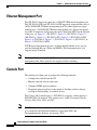
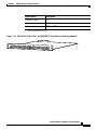
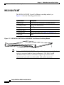
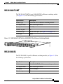
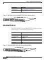
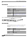
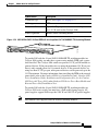
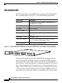
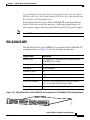
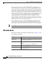
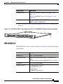
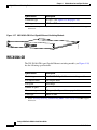
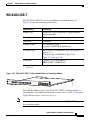
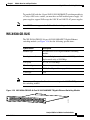
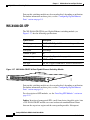
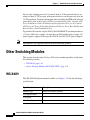
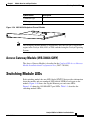
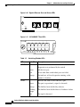
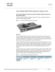
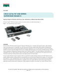
C H A P T E R
1
Module Overview and Specifications
This chapter provides an overview of the features of the Catalyst 4500 series
supervisor engines and switching modules. The information is presented in the
following major sections:
•
Catalyst 4000 Series Switches, page 1-1
•
Catalyst 4500 Series Switches, page 1-2
•
Supervisor Engines, page 1-2
•
Ethernet and Fast Ethernet Switching Modules, page 1-12
•
Gigabit Ethernet Switching Modules, page 1-29
•
Other Switching Modules, page 1-42
•
Switching Module LEDs, page 1-43
•
Hot-Swapping Feature, page 1-45
Catalyst 4000 Series Switches
The Catalyst 4000 series switches consist of the Catalyst 4003 switch and the
Catalyst 4006 switch. The switches are designed for high-performance,
high-density wiring closet applications. A detailed overview of these switches is
in the Catalyst 4000 Series Installation Guide.
Catalyst 4500 Series Module Installation Guide
78-13267-06
1-1
Chapter 1
Module Overview and Specifications
Catalyst 4500 Series Switches
Catalyst 4500 Series Switches
The Catalyst 4500 series switches consist of the Catalyst 4503 switch, the
Catalyst 4506 switch, the Catalyst 4507R switch, and the Catalyst 4510R switch.
The switches are designed for high-performance, high-density wiring closet
applications. A detailed overview of these switches is in the Catalyst 4500 Series
Installation Guide.
Supervisor Engines
These sections describe the supervisor engines available for the Catalyst 4500
series switches:
•
Supervisor Engine I (WS-X4012), which is used in the Catalyst 4003 switch
(Figure 1-1)
•
Supervisor Engine II (WS-X4013, which is used in the Catalyst 4006, 4503,
and 4506 switches (Figure 1-2)
•
Supervisor Engine II-Plus (WS-X4013+), which is used in the Catalyst 4006,
4503, 4506, and 4507R switches (Figure 1-3)
•
Supervisor Engine II-Plus TS (WS-X4013+TS), which is used in Catalyst
4503 switches only (Figure 1-4)
•
Supervisor Engine II-Plus 10GE (WS-X4013+10GE), which is used in
Catalyst 4503, 4506, and 4507R switches (Figure 1-5)
•
Supervisor Engine III (WS-X4014), which is used in the Catalyst 4006, 4503,
and 4506 switches (Figure 1-6)
•
Supervisor Engine IV (WS-X4515), which is used in the Catalyst 4006, 4503,
4506, and 4507R switches (Figure 1-7 )
•
Supervisor Engine V (WS-X4516), which is used in the Catalyst 4006, 4503,
4506, 4507R, and 4510R switches (Figure 1-8)
•
Supervisor Engine V-10GE (WS-X4516-10GE), which is used in the
Catalyst 4503, 4506, 4507R, and 4510R switches (Figure 1-9)
On the Catalyst 4006, 4503, and 4506 switches, you can install the Supervisor
Engine in slot 1 only. On the Catalyst 4507R or 4510R switch, you install the
primary supervisor engine in slot 1, and you can install an optional redundant
supervisor engine in slot 2.
Catalyst 4500 Series Module Installation Guide
1-2
78-13267-06
Chapter 1
Module Overview and Specifications
Supervisor Engines
The supervisor engines have the following features:
•
Data path and control for all network interfaces
•
Management functions:
– Interface monitoring
– Environmental status
– SNMP and console/Telnet interface
•
Hot-swapping
Note
Packets are not forwarded while the module is removed. A system
reboot occurs when a supervisor engine is reinserted.
•
The Supervisor Engine II-Plus TS provides 12 nonblocking
10/100/1000BASE-T (RJ-45) ports and 8 1000BASE-X (SFP) ports.
•
The Supervisor Engine II-Plus 10GE and Supervisor Engine V-10GE provide
2 nonblocking 10GBASE uplink ports.
•
The Supervisor Engine II-Plus 10GE and Supervisor Engine V-10GE provide
4 1000BASE-X (SFP) ports.
•
The Supervisor Engine IV and V support the Catalyst 4500 series NetFlow
Services Card (WS-F4531). NetFlow is integral to the Supervisor Engine
V-10 GE.
To install a supervisor engine, follow the procedure in the “Installing the
Modules” section on page 3-2.
The supervisor engines used in Catalyst 4000 and Catalyst 4500 switches are
shown in Figure 1-1 to Figure 1-8.
Catalyst 4500 Series Module Installation Guide
78-13267-06
1-3
Chapter 1
Module Overview and Specifications
Supervisor Engines
Supervisor Engine I (WS-X4012)
16671
Figure 1-1
0%
100%
STATUS LED
Switch load
indicators
Reset
button
Ethernet
management
port
Figure 1-2
Console
port
Supervisor Engine II (WS-X4013)
Reset button
STATUS LED
UPLINK
UPLINK
STATUS
1
UPLINKS
ENABLE
D
CONSOLE
Gigabit uplink
ports
10/100
BASE-TX
RESET
1%
100%
Switch load
indicators
28844
2
Ethernet
management port
Console
port
Catalyst 4500 Series Module Installation Guide
1-4
78-13267-06
Chapter 1
Module Overview and Specifications
Supervisor Engines
Figure 1-3
Supervisor Engine II-Plus (WS-X4013+)
Reset button
STATUS LED
WS-X45
15 SUP
ERVISO
R ENGINE
IV
UPLINK
1
UPLINK
2
STATUS
LINE ACT
IVE
LINE ACT
IVE
ACTIVE
CONSOLE
10/100
MGT
UTILIZAT
FLASH
100%
Gigabit uplink
ports
LINK
Switch load
indicators
78480
ION
1%
EJECT
RESET
CompactFlash port
Ethernet
management port
Console port
(RJ-45)
Figure 1-4
Supervisor Engine II-Plus TS (WS-X4013+TS)
RESET button
Switch load
indicators
Compact Flash port
Ethernet
management port
CONSOLE
port
113860
STATUS LED
PoE status
LED
Catalyst 4500 Series Module Installation Guide
78-13267-06
1-5
Chapter 1
Module Overview and Specifications
Supervisor Engines
Figure 1-5
Supervisor Engine II-Plus 10GE (WS-X4013+10GE)
CONSOLE port
STATUS LED
Compact
Flash
port
RESET
button
Switch load
indicators
Figure 1-6
120474
Ethernet
management port
10 GE uplink
ports
Gigabit SFP
ports
Supervisor Engine III (WS-X4014)
RESET button
STATUS LED
WS-X401
4
UPLINK 1
UPLINK 2
SUPERVISOR
III ENGINE
STATUS
LINK ACTI
VE
LINK ACTI
VE
10/100 MGT
100%
Gigabit uplink ports
Switch load indicators
CONSOLE port
(RJ-45)
FLASH
RESET
EJECT
78479
CONSOLE
UTILIZATION
1%
CompactFlash port
Management port
Catalyst 4500 Series Module Installation Guide
1-6
78-13267-06
Chapter 1
Module Overview and Specifications
Supervisor Engines
Figure 1-7
Supervisor Engine IV (WS-X4515)
Reset button
STATUS LED
WS-X45
15 SUP
ERVISO
R ENGINE
IV
UPLINK
1
UPLINK
2
STATUS
LINE ACT
IVE
LINE ACT
IVE
ACTIVE
CONSOLE
10/100
MGT
UTILIZAT
78480
ION
FLASH
1%
100%
Gigabit uplink
ports
LINK
Switch load
indicators
EJECT
RESET
CompactFlash port
Ethernet
management port
Console port
(RJ-45)
Figure 1-8
Supervisor Engine V (WS-X4516)
Reset button
STATUS LED
WS-X45
15 SUP
ERVISO
R ENGINE
IV
UPLINK
1
UPLINK
2
STATUS
LINE ACT
IVE
LINE ACT
IVE
ACTIVE
CONSOLE
10/100
MGT
UTILIZAT
FLASH
100%
Gigabit uplink
ports
LINK
Switch load
indicators
78480
ION
1%
EJECT
RESET
CompactFlash port
Ethernet
management port
Console port
(RJ-45)
Catalyst 4500 Series Module Installation Guide
78-13267-06
1-7
Chapter 1
Module Overview and Specifications
Supervisor Engines
Figure 1-9
Supervisor Engine V-10GE (WS-X4516-10GE)
CONSOLE port
STATUS LED
Compact
Flash
port
120474
Ethernet
management port
RESET
button
Switch load
indicators
10 GE uplink
ports
Gigabit SFP
ports
Front-Panel Components
The following connectors, LEDs, and buttons are located on the front panel of the
supervisor engine:
•
The STATUS LED, which indicates the operating state of the module
•
Two Gigabit uplink ports (WS-X4013, WS-X4013+, WS-X4014, and
WS-X4515 supervisor engines only)
•
Four SFP Gigabit uplinks ports and 2 10-Gigabit uplink ports on
WS-X4013+10GE and WS-X4016-10GE.
•
Eight unmarked switch load indicator LEDs, which provide an approximation
of the current traffic across the backplane
•
A console port (DB-25 for the WS-X4012; RJ-45 for the WS-X4013,
WS-X4013+, WS-X4013+ TS, WS-X4013+10GE, WS-X4014, WS-X4515,
WS-X4516, and WS-X4516-10GE supervisor engines)
•
An Ethernet management port (RJ-45)
•
A link status LED, which provides status for the management port
(10BASE-T on the WS-X4012 and 10/100BASE-T on the WS-X4013,
WS-X4013+, WS-X4013+ TS, WS-X4013+10GE, WS-X4014, WS-X4515,
WS-X4516, and WS-X4516-10GE supervisor engines)
Catalyst 4500 Series Module Installation Guide
1-8
78-13267-06
Chapter 1
Module Overview and Specifications
Supervisor Engines
•
The Reset button (recessed), which allows you to reset the system
•
The CompactFlash port and eject button (WS-X4013+, WS-X4013+ TS,
WS-X4013+10GE, WS-4014, WS-X4515, WS-X4516, and
WS-X4516-10GE supervisor engines only) (refer to Using the Compact
Flash on the Catalyst 4000 Family Supervisor Engine III and IV.)
Table 1-1 describes the supervisor engine LEDs.
Table 1-1
LED
Supervisor Engine LEDs
Color/State
Description
STATUS
Indicates the results of a series of self-tests.
Green
All diagnostic tests passed.
Red
A test failed.
Orange
System boot or diagnostic test is in
progress.
Off
Module is disabled.
UTILIZATION Green 1–100%
If the switch is operational, this display
indicates the current traffic load over the
backplane (as an approximate percentage).
LINK
Indicates the status of the 10/100BASE-T
Ethernet management port or uplink ports.
Green
The link is operational.
Orange
The link is disabled by user.
Flashing orange
The power-on self-test indicates a faulty
port.
Off
No signal is detected or there is a link
configuration failure.
ACTIVE
Indicates whether the uplink port is active
or not.
Green
The port is active.
Off
The port is not active.
Catalyst 4500 Series Module Installation Guide
78-13267-06
1-9
Chapter 1
Module Overview and Specifications
Supervisor Engines
Ethernet Management Port
The WS-X4012 supervisor engine has a 10BASE-T Ethernet management port.
The WS-X4516-10GE and WS-X4013+10GE supervisor engine modules have a
10/100/1000BASE-T Ethernet management port.The other supervisor engine
modules have a 10/100BASE-T Ethernet management port. Supervisor engines
use an RJ-45 connector on the front panel with a link status LED. For the location
of the port, see Figure 1-1 (WS-X4012), Figure 1-2 (WS-X4013), Figure 1-3
(WS-X4013+), Figure 1-4 (WS-X4013+TS), Figure 1-5 (WS-X4013+10GE),
Figure 1-6 (WS-X4014), Figure 1-7 (WS-X4515), Figure 1-8 (WS-X4516), or
Figure 1-9 (WS-X4516-10GE).
TCP/IP-based management services available through inband access also are
provided through this port (Telnet and SNMP). This management port also
supports image download.
Note
The 10BASE-T and 10/100BASE-T Ethernet management ports are for network
management only. These ports do not support network switching.
Console Port
The console port allows you to perform the following functions:
•
Configure the switch from the CLI
•
Monitor network statistics and errors
•
Configure SNMP agent parameters
•
Download software updates to the switch or distribute software images
residing in Flash memory to attached devices
The Catalyst 4003 console port is a DCE DB-25 receptacle, which supports a
DCE EIA/TIA-232 interface. The console port is an RJ-45 receptacle on the
Catalyst 4006, 4503, 4506, and 4507.
Note
EIA/TIA-232 was known as recommended standard RS-232 before its acceptance
as a standard by the Electronic Industries Association (EIA) and
Telecommunications Industry Association (TIA).
Catalyst 4500 Series Module Installation Guide
1-10
78-13267-06
Chapter 1
Module Overview and Specifications
Supervisor Engines
Supervisor Memory
Table 1-2 lists the memory and processor specifications for the Supervisor
engines.
Table 1-2
Supervisor Memory
Supervisor Engine
Supervisor Engine II+
256 MB SODIMM SDRAM
32 MB Flash memory
Supervisor Engine II+TS
256 MB SODIMM SDRAM
32 MB Flash memory
Supervisor Engine II+10GE
256 MB SODIMM SDRAM
(upgradeable to 512 MB)
64 MB Flash memory
Supervisor Engine III
256 MB DIMM SDRAM
64 MB Flash memory
512 KB NVRAM
Supervisor Engine IV
512 MB SODIMM SDRAM
64 MB Flash memory
512 KB NVRAM
Supervisor Engine V
512 MB SODIMM SDRAM
64 MB Flash memory
512 KB NVRAM
Supervisor Engine V-10GE
512 MB SODIMM SDRAM
64 MB Flash memory
512 KB NVRAM
Catalyst 4500 Series Module Installation Guide
78-13267-06
1-11
Chapter 1
Module Overview and Specifications
Ethernet and Fast Ethernet Switching Modules
Ethernet and Fast Ethernet Switching Modules
This section describes the Catalyst 4500 series Ethernet and Fast Ethernet
switching modules and includes the following sections:
•
WS-X4124-RJ45, page 1-12
•
WS-X4124-FX-MT, page 1-14
•
WS-X4148-FX-MT, page 1-15
•
WS-X4148-RJ, page 1-15
•
WS-X4148-FE-BD-LC, page 1-16
•
WS-X4148-FE-LX-MT, page 1-17
•
WS-X4148-RJ21, page 1-18
•
WS-X4148-RJ45V, page 1-18
•
WS-X4248-FE-SFP, page 1-20
•
WS-X4224-RJ45V, page 1-20
•
WS-X4248-RJ21V, page 1-22
•
WS-X4248-RJ45V, page 1-23
•
WS-X4232-GB-RJ, page 1-24
•
WS-X4232-L3, page 1-25
•
WS-X4232-RJ-XX, page 1-27
– WS-U4504-FX-MT Uplink Module, page 1-28
WS-X4124-RJ45
The WS-X4124-RJ45 24-port Fast Ethernet switching module (see Figure 1-10)
has the following specifications:
Specification
Description
Module type
10/100BASE-TX Fast Ethernet switching module
Port duplex mode
Half or full duplex mode
Port speed
10 or 100 Mbps
Catalyst 4500 Series Module Installation Guide
1-12
78-13267-06
Chapter 1
Module Overview and Specifications
Ethernet and Fast Ethernet Switching Modules
Specification
Description
Number of ports
24
Connector type
RJ-45 (See Figure 2-1 on page 2-2.)
Cable type
UTP1 or FTP
1. UTP = unshielded twisted-pair
113135
Figure 1-10 WS-X4124-RJ45 24-Port 10/100BASE-TX Fast Ethernet Switching Module
Catalyst 4500 Series Module Installation Guide
78-13267-06
1-13
Chapter 1
Module Overview and Specifications
Ethernet and Fast Ethernet Switching Modules
WS-X4124-FX-MT
The WS-X4124-FX-MT 24-port Fast Ethernet switching module (see
Figure 1-11) has the following specifications:
Specification
Description
Module type
100BASE-FX Fast Ethernet switching module
Port duplex mode
Half or full duplex mode
Port speed
100 Mbps
Number of ports
24
Connector type
MT-RJ fiber-optic (See Figure 2-4 on page 2-4.)
Cable type
MMF
Figure 1-11 WS-X4124-FX-MT 24-Port 100BASE-FX Fast Ethernet Switching Module
24 PORT 100BASE-FX
SWITCHING MODULE
STATUS
1
2
3
4
5
6
Note
7
8
9
10
11
12
13
14
15
16
17
18
19
20
21
22
23
24
29216
WS-X4124-FX-MT
Catalyst 4000 WS-X4124-FX-MT modules with hardware revisions 1.5 and
earlier are supported with the Supervisor Engines I (WS-X4012) and II
(WS-X4013) only. Contact your technical support representative for a
replacement if you need to use this module with another supervisor.
Catalyst 4500 Series Module Installation Guide
1-14
78-13267-06
Chapter 1
Module Overview and Specifications
Ethernet and Fast Ethernet Switching Modules
WS-X4148-FX-MT
The WS-X4148-FX-MT 48-port 100BASE-FX Fast Ethernet switching module
(see Figure 1-12) has the following specifications:
Specification
Description
Module type
100BASE-FX Fast Ethernet switching module
Port duplex mode
Half or full duplex mode
Port speed
100 Mbps
Number of ports
48
Connector type
MT-RJ fiber-optic (See Figure 2-4 on page 2-4.)
Cable type
MMF
Figure 1-12 WS-X4148-FX-MT 48-Port 100BASE-FX Fast Ethernet Switching Module
WS-X4188-FX-MT
1
3
5
7
9
11
13
15
17
19
21
23
25
27
29
31
33
35
37
39
41
43
45
47
42
44
46
48
2
4
6
8
10
12
14
16
18
20
22
24
26
28
30
32
34
36
38
40
49434
48 PORT 100BASE-FX
SWITCHING MODULE
STATUS
WS-X4148-RJ
The WS-X4148-RJ 48-port Fast Ethernet switching module (see Figure 1-13) has
the following specifications:
Specification
Description
Module type
10/100BASE-TX Fast Ethernet switching module
Port duplex mode
Half or full duplex mode
Port speed
10 or 100 Mbps
Number of ports
48
Catalyst 4500 Series Module Installation Guide
78-13267-06
1-15
Chapter 1
Module Overview and Specifications
Ethernet and Fast Ethernet Switching Modules
Specification
Description
Connector type
RJ-45 (See Figure 2-1 on page 2-2.)
Cable type
UTP1 or FTP
1. UTP = unshielded twisted-pair
Figure 1-13 WS-X4148-RJ 48-Port 10/100BASE-TX Fast Ethernet Switching Module
1
2
3
4
5
6
7
8
9
10
11
12
13
14
15
16
17
18
19
20
21
22
23
24
25
26
27
28
29
30
31
32
33
34
35
36
25
26
27
28
29
30
31
32
33
34
35
36
STATUS
28
33
27
34
26
36
25
35
28
29
27
30
26
31
25
32
ETHENET
SWITCHING MODULE
34
16
36
15
35
14
29
13
30
4 PORT
10/100 BaseT
31
12
32
11
33
10
22
9
24
8
23
7
17
6
18
5
19
4
20
3
21
2
17408
WS-X4148-RJ
WS-X4148-FE-BD-LC
The WS-X4148-FE-BD-LC 48-port 100BASE-BX10-D Fast Ethernet switching
module (see Figure 1-14) has the following specifications:
Specification
Description
Module type
100BASE-BX10-D Fast Ethernet switching module
Port duplex mode
Full duplex mode
Port speed
100 Mbps
Number of ports
48
Connector type
Single LC (See Figure 1-15.)
Cable type
SMF
WS-4448-GB-LX
1
3
5
7
9
11
13
15
17
19
21
23
25
27
29
31
33
35
37
2
39
4
6
41
8
43
45
10
47
12
14
16
18
20
22
24
26
28
30
32
34
36
38
40
42
44
46
48
STATUS
2
4
6
8
10
12
14
16
18
20
22
24
26
28
30
32
34
36
38
40
42
44
46
48
55780
Figure 1-14 WS-X4148-FE-BD-LC 48-Port Fast Ethernet Switching Module
Catalyst 4500 Series Module Installation Guide
1-16
78-13267-06
Chapter 1
Module Overview and Specifications
Ethernet and Fast Ethernet Switching Modules
105887
Figure 1-15 Single LC Connector
WS-X4148-FE-LX-MT
The WS-X4148-FE-LX-MT 48-port 100BASE-LX10 Fast Ethernet switching
module (see Figure 1-16) has the following specifications:
Specification
Description
Module type
100BASE-LX10 Fast Ethernet switching module
Port duplex mode
Half or full duplex mode
Port speed
100 Mbps
Number of ports
48
Connector type
MT-RJ fiber-optic (See Figure 2-4 on page 2-4.)
Cable type
SMF
Figure 1-16 WS-X4148-FE-LX-MT 48-Port 100BASE-LX-MT Fast Ethernet Switching Module
3
5
7
9
11
13
15
17
19
21
23
25
27
29
31
33
35
37
39
41
43
45
47
STATUS
2
4
6
8
10
12
14
16
18
20
22
24
26
28
30
32
34
36
38
40
42
44
46
48
85381
1
WS-X4188-FX-MT
48 PORT 100BASE-FX
SWITCHING MODULE
Catalyst 4500 Series Module Installation Guide
78-13267-06
1-17
Chapter 1
Module Overview and Specifications
Ethernet and Fast Ethernet Switching Modules
WS-X4148-RJ21
The WS-X4148-RJ21 48-port Fast Ethernet switching module (see Figure 1-17)
has the following specifications:
Specification
Description
Module type
10/100BASE-TX Fast Ethernet switching module
Port duplex mode
Half or full duplex mode
Port speed
10 or 100 Mbps
Number of ports
48
Connector type
RJ-21 (See Figure 2-5 on page 2-5 or Figure 2-6 on
page 2-5.)
Cable type
Category 5 UTP
Figure 1-17 WS-X4148-RJ21 48-Port 10/100-Mbps Fast Ethernet Switching Module
WS-X4148-RJ21
STATUS
1
2
3
4
5 6
7
8
9 10 11 12
13 14 15 16 17 18 19 20
21 22 23 24
25 26 27 28 29 30 31 32
33 34 35 36
37 38 39 40 41 42 43 44
45 46 47 48
29217
10/100 FAST ETHERNET
WS-X4148-RJ45V
The WS-X4148-RJ45V 48-port Cisco pre-standard Power over Ethernet (PoE)
10/100BASE-TX switching module (see Figure 1-18) has the following
specifications:
Specification
Description
Module type
10/100BASE-TX Fast Ethernet switching module
with Cisco pre-standard PoE
Port duplex mode
Half or full duplex mode
Port speed
10 or 100 Mbps
Catalyst 4500 Series Module Installation Guide
1-18
78-13267-06
Chapter 1
Module Overview and Specifications
Ethernet and Fast Ethernet Switching Modules
Specification
Description
Number of ports
48
Connector type
RJ-45 (See Figure 2-1 on page 2-2.)
Cable type
UTP
Power over Ethernet
6.3 W per-powered device on a port, on all 48 ports
Figure 1-18 WS-X4148-RJ45V 48-Port PoE 10/100BASE-TX Switching Module
1
2
3
4
5
6
7
8
9
10
11
12
13
14
15
16
17
18
19
20
21
22
23
24
25
26
27
28
29
30
31
32
33
34
35
36
25
26
27
28
29
30
31
32
33
34
35
36
STATUS
SWITCHING
MODULE
PHONE
33
28
34
27
36
26
35
25
29
28
30
27
31
26
32
25
34
10/100BASE-TX
ETHERNET
36
16
35
15
29
14
30
13
31
12
32
11
33
10
22
9
24
8
48 PORT
IN_LINE POWER
23
7
17
6
18
5
19
4
20
3
21
2
41854
WS-X4648-PWR
DC IN-LINE
To provide PoE with the 48-port PoE 10/100BASE-TX switching module in a
Catalyst 4006 switch, you must have a power entry module (PEM) and a power
shelf installed. For more information about installing the PEM or the external
power shelf, refer to the Catalyst 4000 Series Installation Guide, Catalyst 4500
Series Installation Guide, Installation and Configuration Note for the Catalyst
4500 Series AC Power Shelf, or the Catalyst 4500 Series Power Entry Module and
External Power Shelf Installation Note.
To provide PoE with the 48-port PoE 10/100BASE-TX switching module in a
Catalyst 4500 series switch, you must have a PoE-enabled power supply. All
power supplies support PoE except the 1000 W and 1400 W AC power supplies.
Note
Auto MDIX is not supported on PoE enabled switching modules.
Catalyst 4500 Series Module Installation Guide
78-13267-06
1-19
Chapter 1
Module Overview and Specifications
Ethernet and Fast Ethernet Switching Modules
WS-X4248-FE-SFP
The WS-X4248-FE-SFP 48-port 100BASE-X Fast Ethernet switching module
(see Figure 1-19) has the following specifications:
Specification
Description
Module type
100BASE-X Fast Ethernet switching module
Port duplex mode
Half or full duplex mode
Port speed
100 Mbps
Number of ports
48
Connector type
LC type (See Figure 2-9 on page 2-6.)
Cable type
MMF or SMF
SFP type
FX, LX10, BX-D and BX-U
WS-4448-GB-LX
1
3
5
7
9
11
13
15
17
19
21
23
25
27
29
31
33
35
37
2
39
4
6
41
8
43
45
10
47
12
14
16
18
20
22
24
26
28
30
32
34
36
38
40
42
44
46
48
STATUS
2
4
6
8
10
12
14
16
18
20
22
24
26
28
30
32
34
36
38
40
42
44
46
48
55780
Figure 1-19 WS-X4248-FE-SFP 48-Port 100BASE-X Fast Ethernet Switching Module
WS-X4224-RJ45V
The WS-X4224-RJ45V 24-port IEEE 802.3af-compliant PoE 10/100BASE-TX
switching module (see Figure 1-20) has the following specifications:
Specification
Description
Module type
10/100BASE-TX Fast Ethernet switching module
with IEEE 802.3af PoE
Port duplex mode
Half or full duplex mode
Port speed
10 or 100 Mbps
Number of ports
24
Catalyst 4500 Series Module Installation Guide
1-20
78-13267-06
Chapter 1
Module Overview and Specifications
Ethernet and Fast Ethernet Switching Modules
Specification
Description
Connector type
RJ-45 (See Figure 2-1 on page 2-2.)
Cable type
UTP
Power over Ethernet
Up to 15.4 W per powered device on all 24 ports
(to a 312 W total on the Catalyst 4006)
Power regulation
Internal on the switching module
113136
Figure 1-20 WS-X4224-RJ45V 24-Port IEEE 802.3af-Compliant PoE 10/100BASE-TX Switching Module
To provide PoE with the 24-port PoE 10/100BASE-TX switching module in a
Catalyst 4006 switch, you must have a power entry module (PEM) and a power
shelf installed. The Catalyst 4006 switch can provide 312 W per PoE module to
powered devices. If the powered devices are using the maximum 15.4 W per port,
there is only enough power for 18 powered devices. If the powered devices are
using less than 15.4 W per port, more powered devices can be powered, up to the
312 W maximum. For more information about installing the PEM or the external
power shelf, refer to the Catalyst 4000 Series Installation Guide, Catalyst 4500
Series Installation Guide, Installation and Configuration Note for the Catalyst
4500 Series AC Power Shelf, or the Catalyst 4500 Series Power Entry Module and
External Power Shelf Installation Note.
To provide PoE with the 24-port PoE 10/100BASE-TX switching module in a
Catalyst 4500 series switch, you must have a PoE-enabled power supply. All
power supplies support PoE except the 1000 W and 1400 W AC power supplies.
Note
Auto MDIX is not supported on PoE enabled switching modules.
Catalyst 4500 Series Module Installation Guide
78-13267-06
1-21
Chapter 1
Module Overview and Specifications
Ethernet and Fast Ethernet Switching Modules
WS-X4248-RJ21V
The WS-X4248-RJ21V 48-port IEEE 802.3af-compliant PoE 10/100BASE-TX
RJ-21 switching module (see Figure 1-21) has the following specifications:
Specification
Description
Module type
10/100BASE-TX Fast Ethernet switching module
with IEEE 802.3af PoE
Port duplex mode
Half or full duplex mode
Port speed
10 or 100 Mbps
Number of ports
48
Connector type
RJ-21 (See Figure 2-5 on page 2-5 or Figure 2-6 on
page 2-5.)
Cable type
Category 5 UTP
Power over Ethernet
Up to 15.4 W per powered device on all 48 ports
(to a 312 W total on the Catalyst 4006)
Power regulation
Internal on the switching module
Figure 1-21 WS-X4248-RJ21V IEEE 802.3af-Compliant PoE 48-Port 10/100-Mbps Switching Module
WS-X4148-RJ21
STATUS
1
2
3
4
5 6
7
8
9 10 11 12
13 14 15 16 17 18 19 20
21 22 23 24
25 26 27 28 29 30 31 32
33 34 35 36
37 38 39 40 41 42 43 44
45 46 47 48
29217
10/100 FAST ETHERNET
To provide PoE with the 48-port PoE 10/100BASE-TX switching module in a
Catalyst 4006 switch, you must have a power entry module (PEM) and power
shelf installed. The Catalyst 4006 switch can provide 312 W per PoE module to
powered devices. If the powered devices are using the maximum 15.4 W per port,
there is only enough power for 18 powered devices. If the powered devices are
using less than 15.4 W per port, more powered devices can be powered, up to the
312 W maximum. For more information about installing the PEM or the external
power shelf, refer to the Catalyst 4000 Series Installation Guide, Catalyst 4500
Catalyst 4500 Series Module Installation Guide
1-22
78-13267-06
Chapter 1
Module Overview and Specifications
Ethernet and Fast Ethernet Switching Modules
Series Installation Guide, Installation and Configuration Note for the Catalyst
4500 Series AC Power Shelf, or the Catalyst 4500 Series Power Entry Module and
External Power Shelf Installation Note.
To provide PoE with the 48-port PoE 10/100BASE-TX switching module in a
Catalyst 4500 series switch, you must have a PoE-enabled power supply. All
power supplies support PoE except the 1000 W and 1400 W AC power supplies.
Auto MDIX is not supported on PoE enabled switching modules.
Note
WS-X4248-RJ45V
The WS-X4248-RJ45V 48-port IEEE 802.3af-compliant PoE 10/100BASE-TX
switching module (see Figure 1-22) has the following specifications:
Specification
Description
Module type
10/100BASE-TX Fast Ethernet switching module
with IEEE 802.3af PoE
Port duplex mode
Half or full duplex mode
Port speed
10 or 100 Mbps
Number of ports
48
Connector type
RJ-45 (See Figure 2-1 on page 2-2.)
Cable type
UTP
Power over Ethernet
Up to 15.4 W per powered device on all 48 ports
(to a 312 W total on the Catalyst 4006)
Power regulation
Internal on the switching module
Figure 1-22 WS-X4248-RJ45V 48-Port IEEE 802.3af-Compliant PoE 10/100BASE-TX Switching Module
1
2
3
4
5
6
7
8
9
10
11
12
13
14
15
16
17
18
19
20
21
22
23
24
25
26
27
28
29
30
31
32
33
34
35
36
25
26
27
28
29
30
31
32
33
34
35
36
STATUS
SWITCHING
MODULE
28
PHONE
33
27
34
26
36
25
35
28
29
27
30
26
31
25
32
10/100BASE-TX
ETHERNET
34
16
36
15
35
14
29
13
30
48 PORT
IN_LINE POWER
31
12
32
11
33
10
22
9
24
8
23
7
17
6
18
5
19
4
20
3
21
2
85382
WS-X4648-PWR
DC IN-LINE
Catalyst 4500 Series Module Installation Guide
78-13267-06
1-23
Chapter 1
Module Overview and Specifications
Ethernet and Fast Ethernet Switching Modules
To provide PoE with the 48-port PoE 10/100BASE-TX switching module in a
Catalyst 4006 switch, you must have a power entry module (PEM) and a power
shelf installed. The Catalyst 4006 switch can provide 312 W per PoE module to
powered devices. If the powered devices are using the maximum 15.4 W per port,
there is only enough power for 18 powered devices. If the powered devices are
using less than 15.4 W per port, more powered devices can be powered, up to the
312 Watt maximum. For more information about installing the PEM or the
external power shelf, refer to the Catalyst 4000 Series Installation Guide,
Catalyst 4500 Series Installation Guide, Installation and Configuration Note for
the Catalyst 4500 Series AC Power Shelf, or the Catalyst 4500 Series Power Entry
Module and External Power Shelf Installation Note.
To provide PoE with the 48-port PoE 10/100BASE-TX switching module in a
Catalyst 4500 series switch, you must have a PoE-enabled power supply. All
power supplies support PoE except the 1000 W and 1400 W AC power supplies.
Note
Auto MDIX is not supported on PoE enabled switching modules.
WS-X4232-GB-RJ
The WS-X4232-GB-RJ 34-port Ethernet switching module (see Figure 1-23) has
the following specifications:
Specification
Description
Module type
10/100BASE-TX Ethernet plus 1000BASE-X Gigabit
Ethernet switching module
Port duplex mode
Half or full duplex mode on the 10/100BASE-TX
ports
Full duplex mode on the 1000BASE-X ports
Port speed
10, 100, and 1000 Mbps
Number of ports
32 10/100BASE-TX ports
2 1000BASE-X1 ports
Catalyst 4500 Series Module Installation Guide
1-24
78-13267-06
Chapter 1
Module Overview and Specifications
Ethernet and Fast Ethernet Switching Modules
Specification
Description
Connector type
RJ-45 10/100BASE-TX ports (See Figure 2-1 on
page 2-2.)
SC-type 1000BASE-X ports1 (See Figure 2-16 on
page 2-18.)
Cable type
Category 5 UTP (10/100BASE-TX)
MMF or SMF (1000BASE-X)
1. See the “Installing, Removing, and Maintaining GBICs” section on page 2-8 for GBIC support
information.
Figure 1-23 WS-X4232-GB-RJ 2-Port Gigabit and 32-Port 10/100BASE-T Ethernet Switching Module
1
16672
1
13
13
WS-X4232-L3
The WS-X4232-L3 Layer 3 services module (see Figure 1-24) has the following
specifications:
Specification
Description
Module type
Layer 3 services module
Port duplex mode
Half or full duplex mode on the 10/100BASE-TX
ports
Full duplex mode on the 1000BASE-X Layer 3 ports
Port speed
10, 100, and 1000 Mbps
Number of ports
32 10/100BASE-TX ports
2 1000BASE-X ports
1 console port
1 10BASE-T uplink port
Catalyst 4500 Series Module Installation Guide
78-13267-06
1-25
Chapter 1
Module Overview and Specifications
Ethernet and Fast Ethernet Switching Modules
Specification
Description
Connector type
RJ-45 10/100BASE-TX ports (See Figure 2-1 on
page 2-2.)
SC-type 1000BASE-X ports1 (See Figure 2-16 on
page 2-18.)
RJ-45 (console and 10BASE-T ports) (See Figure 2-1
on page 2-2.)
Cable type
Category 5 UTP (10/100BASE-TX)
MMF or SMF (1000BASE-X)
Category 3 or Category 5 UTP (console and
10BASE-T ports)
1. See the “Installing, Removing, and Maintaining GBICs” section on page 2-8 for GBIC support
information.
For more information, refer to the Installation and Configuration Note for the
Catalyst 4000 Layer 3 Services Module.
Figure 1-24 WS-X4232-L3 Layer 3 Services Module
WS-X4232-L3
CONSOLE
10BASE-MGT
LINK
3
UPLINK
17
19
18
20
STATUS
4
1
2
3
4
5
6
7
8
9
10
11 12
13 14
15 16
17 18
19 20
21 22
23 24
25 26
27 28
34
29 30
31 32
33 34
29219
33
10/100 BASEX-TX
L3 ROUTING MODULE
Catalyst 4500 Series Module Installation Guide
1-26
78-13267-06
Chapter 1
Module Overview and Specifications
Ethernet and Fast Ethernet Switching Modules
WS-X4232-RJ-XX
The WS-X4232-RJ-XX 32-port Ethernet switching module (see Figure 1-25) has
the following specifications:
Specification
Description
Module type
10/100BASE-TX plus 100BASE-FX Ethernet
switching module
Port duplex mode
Half or full duplex mode on both the
10/100BASE-TX and the 100BASE-FX ports
Port speed
10 and 100 Mbps
Number of ports
32 10/100BASE-TX ports
4 optional 100BASE-FX ports on an optional uplink
module (WS-U4504-FX-MT)
Connector type
RJ-45 32 10/100BASE-TX ports (See Figure 2-1 on
page 2-2.)
MT-RJ for the 4 optional ports 100BASE-FX (See
Figure 2-4 on page 2-4.)
Cable type
Category 5 UTP (10/100BASE-TX)
MMF or SMF (100BASE-FX)
Figure 1-25 WS-X4232-RJ-XX 32-port Ethernet Switching Module
WS-X4232-RJ-XX
WS-U4504-FX-MT
4
5
6
7
8
9
10
11
12
13
14
15
16
17
18
19
20
21
22
23
24
25
26
27
28
29
30
31
32
UPLINK
STATUS
Note
28472
3
N+
3
2
N+
4
1
N+
1
STATUS
N+
2
10/100FE
The WS-X4232-RJ-XX Ethernet switching module can operate with or without
the WS-U4504-FX-MT uplink module installed.
Catalyst 4500 Series Module Installation Guide
78-13267-06
1-27
Chapter 1
Module Overview and Specifications
Ethernet and Fast Ethernet Switching Modules
WS-U4504-FX-MT Uplink Module
The WS-U4504-FX-MT uplink module (see Figure 1-26) has the following
specifications:
Specification
Description
Module type
100BASE-FX uplink module
Port duplex mode
Half or full duplex mode
Port speed
100 Mbps
Number of ports
4
Connector type
MT-RJ (See Figure 2-4 on page 2-4.)
Cable type
MMF cable
Figure 1-26 WS-U4504-FX-MT Uplink Module
23837
+4
N
+3
N
+2
N
N
+1
WS-U4504-FX-MT
The WS-U4504-FX-MT uplink module is installed onto a switching module to
provide optional port configurations.
Each port has a port link status LED below it, which is labeled N+x. The N
indicates the last number of the port that is used on the Ethernet switching module
(WS-X4232-RJ-XX).
For the far left port on the WS-U4504-FX-MT uplink module, add 1 to that
number; for the second port, add 2; for the third port, add 3; for the last port, add 4.
Catalyst 4500 Series Module Installation Guide
1-28
78-13267-06
Chapter 1
Module Overview and Specifications
Gigabit Ethernet Switching Modules
Gigabit Ethernet Switching Modules
This section describes the Catalyst 4500 series Gigabit Ethernet switching
modules and includes the following sections:
•
WS-X4302-GB, page 1-29
•
WS-X4306-GB, page 1-30
•
WS-X4506-GB-T, page 1-31
•
WS-X4412-2GB-T, page 1-33
•
WS-X4418-GB, page 1-34
•
WS-X4424-GB-RJ45, page 1-35
•
WS-X4448-GB-LX, page 1-36
•
WS-X4448-GB-RJ45, page 1-37
•
WS-X4524-GB-RJ45V, page 1-38
•
WS-X4548-GB-RJ45, page 1-39
•
WS-X4448-GB-SFP, page 1-40
•
WS-X4548-GB-RJ45V, page 1-41
•
WS-X4019, page 1-42
•
Access Gateway Module (WS-X4604-GWY), page 1-43
WS-X4302-GB
The WS-X4302-GB 2-port Gigabit Ethernet switching module (see Figure 1-27)
has the following specifications:
Specification
Description
Module type
1000BASE-X Gigabit Ethernet switching module
Port duplex mode
Full duplex mode
Port speed
1000 Mbps
Number of ports
2
Catalyst 4500 Series Module Installation Guide
78-13267-06
1-29
Chapter 1
Module Overview and Specifications
Gigabit Ethernet Switching Modules
Specification
Description
Connector type
SC type1 (See Figure 2-16 on page 2-18.)
Cable type
MMF or SMF
1. See the “Installing, Removing, and Maintaining GBICs” section on page 2-8 for GBIC support
information.
1
94138
Figure 1-27 WS-X4302-GB 2-Port Gigabit Ethernet Switching Module
2
WS-X4306-GB
The WS-X4306-GB 6-port Gigabit Ethernet switching module (see Figure 1-28)
has the following specifications:
Specification
Description
Module type
1000BASE-X Gigabit Ethernet switching module
Port duplex mode
Full duplex mode
Port speed
1000 Mbps
Number of ports
6
Connector type
SC type1 (See Figure 2-16 on page 2-18.)
Cable type
MMF or SMF
1. See the “Installing, Removing, and Maintaining GBICs” section on page 2-8 for GBIC support
information.
Catalyst 4500 Series Module Installation Guide
1-30
78-13267-06
Chapter 1
Module Overview and Specifications
Gigabit Ethernet Switching Modules
16673
Figure 1-28 WS-X4306-GB 6-Port Gigabit Ethernet Switching Module
WS-X4506-GB-T
The WS-X4506-GB-T 6-port Gigabit Ethernet switching module (see
Figure 1-28) has the following specifications:
Specification
Description
Module type
10/100/1000BASE-T Fast Ethernet with IEEE802.3af
PoE or 1000BASE-X SFP Gigabit Ethernet switching
module
Port duplex mode
Half or full duplex mode
Port speed
10, 100, or 1000 Mbps
Number of ports
6 total
Connector type
RJ-45 (See Figure 2-1 on page 2-2.)
LC type (See Figure 2-9 on page 2-6.)
Note
Cable type
Category 5 UTP (1000BASE-T)
MMF or SMF (1000BASE-X, LX fiber-optic cable
only)
Power over Ethernet
Up to 15.4 W per powered device on all 6 ports
There are six10/100/1000BASE-T and six 1000BASE-X SFP Gigabit Ethernet
connectors present. Use the select media sfp | rj45 command to set whether a
specific port number uses the SFP or RJ-45 connector. SFP is the default.
Catalyst 4500 Series Module Installation Guide
78-13267-06
1-31
Chapter 1
Module Overview and Specifications
Gigabit Ethernet Switching Modules
113137
Figure 1-29 WS-X4506-GB-T 6-Port Gigabit Ethernet Switching Module
To provide PoE with the 6-port Gigabit Ethernet switching module in a Catalyst
4006 switch, you must have a power entry module (PEM) and power shelf
installed. For more information about installing the PEM or the external power
shelf, refer to the Catalyst 4000 Series Installation Guide, Catalyst 4500 Series
Installation Guide, Installation and Configuration Note for the Catalyst 4500
Series AC Power Shelf, or the Catalyst 4500 Series Power Entry Module and
External Power Shelf Installation Note.
To provide PoE with the 6-port Gigabit Ethernet switching module in a Catalyst
4500 series switch, you must have a PoE-enabled power supply.
Note
Auto MDIX is not supported on PoE enabled switching modules.
Catalyst 4500 Series Module Installation Guide
1-32
78-13267-06
Chapter 1
Module Overview and Specifications
Gigabit Ethernet Switching Modules
WS-X4412-2GB-T
The WS-X4412-2GB-T 14-port Gigabit Ethernet switching module (see
Figure 1-30) has the following specifications:
Specification
Description
Module type
1000BASE-T plus 1000BASE-X Gigabit Ethernet
switching module
Port duplex mode
Full duplex mode
Port speed
1000 Mbps
Number of ports
12 1000BASE-T ports
2 optional 1000BASE-X1 uplink ports
Connector type
RJ-45 for the 12 1000BASE-T ports (See Figure 2-1
on page 2-2.)
SC-type for the 2 1000BASE-X ports1 (See
Figure 2-16 on page 2-18.)
Cable type
Category 5 UTP (1000BASE-T)
MMF or SMF (1000BASE-X)
1. See the “Installing, Removing, and Maintaining GBICs” section on page 2-8 for GBIC support
information.
Figure 1-30 WS-X4412-2GB-T 14-Port Gigabit Ethernet Switching Module
1000BASE-TX GIGABIT ETHERNET
SWITCHING MODULE
STATUS
1
2
3
4
5
6
7
8
9
10
11
12
17
18
29319
WS-X4412-2GB-TX
Some Gigabit Ethernet ports on the WS-X4412-2GB-T switching module are
oversubscribed. For additional information on these ports, see the “Configuring
Gigabit Ethernet Ports” section on page 3-9.
Note
You must use Category 5 cables when connecting to the 1000BASE-T ports on
this switching module.
Catalyst 4500 Series Module Installation Guide
78-13267-06
1-33
Chapter 1
Module Overview and Specifications
Gigabit Ethernet Switching Modules
The two Gigabit Ethernet ports can be configured with any combination of
shortwave (SX), longwave/long-haul (LX/LH), and long-range (ZX) GBICs. For
a description of GBICs, see the “Installing, Removing, and Maintaining GBICs”
section on page 2-8.
WS-X4418-GB
The WS-X4418-GB 18-port Gigabit Ethernet switching module (see Figure 1-31)
has the following specifications:
Specification
Description
Module type
1000BASE-X Gigabit Ethernet switching module
Port duplex mode
Full duplex mode
Port speed
1000 Mbps
Number of ports
18
Connector type
SC type1 (See Figure 2-16 on page 2-18.)
Cable type
MMF or SMF
1. See the “Installing, Removing, and Maintaining GBICs” section on page 2-8 for GBIC support
information.
18147
Figure 1-31 WS-X4418-GB 18-Port Gigabit Ethernet Switching Module
Some ports on this switching module are oversubscribed. For further information
on these ports, see the “Configuring Gigabit Ethernet Ports” section on page 3-9.
Note
WS-X4418-GB does not support WS-G5483, which is the 1000BASE-T GBIC.
Catalyst 4500 Series Module Installation Guide
1-34
78-13267-06
Chapter 1
Module Overview and Specifications
Gigabit Ethernet Switching Modules
The ports on this switching module can be configured with any combination of
shortwave (SX), longwave/long-haul (LX/LH), and long-range (ZX) GBICs. For
a description of GBICs, see the “Installing, Removing, and Maintaining GBICs”
section on page 2-8.
WS-X4424-GB-RJ45
The WS-X4424-GB-RJ45 24-port 10/100/1000BASE-T Gigabit Ethernet
switching module (see Figure 1-32) has the following specifications:
Specification
Description
Module type
10/100/1000 Fast or Gigabit Ethernet switching
module
Port duplex mode
Half or full duplex mode at 10 and 100 Mbps; full
duplex mode only at 1000 Mbps
Port speed
10, 100, or 1000 Mbps
Number of ports
24
Connector type
RJ-45 (See Figure 2-1 on page 2-2.)
Cable type
UTP
You must use Category 5 cables when connecting to the 1000BASE-T ports on
this switching module.
Note
Figure 1-32 WS-X4424-GB-RJ45 24-Port 10/100/1000BASE-T Gigabit Ethernet Switching Module
WS-X4424-GB-RJ45
24 PORT
10/1000/BASE-T
11
2
3
4
5
6
7
8
9
MULIT-SPEED
GIGABIT ETHERNET
SWITCHING
MODULE
10
11
12
13
14
15
16
17
18
19
20
21
22
23
24
49435
STATUS
Ports on this switching module may be oversubscribed, depending on utilization.
For further information on these ports, see the “Configuring Gigabit Ethernet
Ports” section on page 3-9.
Catalyst 4500 Series Module Installation Guide
78-13267-06
1-35
Chapter 1
Module Overview and Specifications
Gigabit Ethernet Switching Modules
WS-X4448-GB-LX
The WS-X4448-GB-LX 48-port Gigabit Ethernet switching module (see
Figure 1-33) has the following specifications:
Specification
Description
Module type
1000BASE-X Gigabit Ethernet switching module
Port duplex mode
Full duplex mode
Port speed
1000 Mbps
Number of ports
48
Connector type
LC type (See Figure 2-9 on page 2-6.)
Cable type
MMF or SMF (LX fiber-optic cable only)
WS-4448-GB-LX
1
3
5
7
9
11
13
15
17
19
21
23
25
27
29
31
33
35
37
2
39
4
6
41
8
43
45
10
47
12
14
16
18
20
22
24
26
28
30
32
34
36
38
40
42
44
46
48
STATUS
2
4
6
8
10
12
14
16
18
20
22
24
26
28
30
32
34
36
38
40
42
44
46
48
55780
Figure 1-33 WS-X4448-GB-LX 48-Port Gigabit Ethernet Switching Module
Ports on this switching module may be oversubscribed, depending on utilization.
For further information on these ports, see the “Configuring Gigabit Ethernet
Ports” section on page 3-9.
The 48 ports can be configured with any combination of small, form-factor
pluggable (SFP) modules. For a description of SFP modules, see the “Installing
SFP Modules” section on page 2-22.
Problem Insertion of unsupported SFPs (small form-factor pluggable optics) into
a WS-X4448-GB-LX module can cause undetected communication failures
between the supervisor engine and the corresponding module. Subsequent
insertion or removal of SFPs from the module is not recognized by the system.
This activity can be observed on a Catalyst 4500 series switch using Release
12.1(12c)EW1 or later releases.
Solution Reset the module with the hw-module module reset command.
(CSCee05078)
Catalyst 4500 Series Module Installation Guide
1-36
78-13267-06
Chapter 1
Module Overview and Specifications
Gigabit Ethernet Switching Modules
WS-X4448-GB-RJ45
The WS-X4448-GB-RJ45 48-port 10/100/1000BASE-T Gigabit Ethernet
switching module (see Figure 1-34) has the following specifications:
Specification
Description
Module type
10/100/1000 Fast or Gigabit Ethernet switching
module
Port duplex mode
Half or full duplex mode at 10 and 100 Mbps; full
duplex mode only at 1000 Mbps
Port speed
10, 100, or 1000 Mbps
Number of ports
48
Connector type
RJ-45 (See Figure 2-1 on page 2-2.)
Cable type
UTP
You must use Category 5 cables when connecting to the 1000BASE-T ports on
this switching module.
Note
Figure 1-34 WS-X4448-GB-RJ45 48-Port 10/100/1000BASE-T Gigabit Ethernet Switching Module
STATUS
1
2
3
4
5
6
7
8
9
10
11
12
13
14
15
16
10/100BASE-TX
ETHERNET
17
18
19
20
21
22
23
24
25
26
27
28
29
30
31
MULTI-SPEED
GIGABIT ETHERNET
32 SWITCHING MODULE 33
34
35
36
37
38
39
40
41
42
43
44
45
46
47
48
63419
WS-X4448-GB-RJ45
Ports on this switching module may be oversubscribed, depending on utilization.
For further information on these ports, see the “Configuring Gigabit Ethernet
Ports” section on page 3-9.
Catalyst 4500 Series Module Installation Guide
78-13267-06
1-37
Chapter 1
Module Overview and Specifications
Gigabit Ethernet Switching Modules
WS-X4524-GB-RJ45V
The WS-X4524-GB-RJ45V 24-port IEEE 802.3af-compliant PoE
10/100/1000BASE-T RJ-45 switching module (see Figure 1-35) has the following
specifications:
Specification
Description
Module type
10/100/1000BASE-T Fast Ethernet switching module
with IEEE802.3af PoE
Port duplex mode
Half or full duplex mode
Port speed
10, 100, or 1000 Mbps
Number of ports
24
Connector type
RJ-45 (See Figure 2-1 on page 2-2.)
Cable type
UTP
Power over Ethernet
Up to 15.4 W per powered device on all 24 ports
(to a 312 W total on the Catalyst 4006)
113138
Figure 1-35 WS-X4524-GB-RJ45V 24-Port IEEE-Compliant PoE 10/100/1000BASE-T Switching Module
To provide PoE with the 24-port PoE 10/100BASE-TX switching module in a
Catalyst 4006 switch, you must have a power entry module (PEM) and a power
shelf installed. The Catalyst 4006 switch can provide 312 W per PoE module to
powered devices. If the powered devices are using the maximum 15.4 W per port,
there is only enough power for 18 powered devices. If the powered devices are
using less than 15.4 W per port, more powered devices can be powered, up to the
312 Watt maximum. For more information about installing the PEM or the
external power shelf, refer to the Catalyst 4000 Series Installation Guide,
Catalyst 4500 Series Installation Guide, Installation and Configuration Note for
the Catalyst 4500 Series AC Power Shelf, or the Catalyst 4500 Series Power Entry
Module and External Power Shelf Installation Note.
Catalyst 4500 Series Module Installation Guide
1-38
78-13267-06
Chapter 1
Module Overview and Specifications
Gigabit Ethernet Switching Modules
To provide PoE with the 24-port PoE 10/100/1000BASE-T switching module in
a Catalyst 4500 series switch, you must have an PoE-enabled power supply. All
power supplies support PoE except the 1000 W and 1400 W AC power supplies.
Auto MDIX is not supported on PoE enabled switching modules.
Note
WS-X4548-GB-RJ45
The WS-X4548-GB-RJ45 48-port 10/100/1000BASE-T Gigabit Ethernet
switching module (see Figure 1-36) has the following specifications:
Specification
Description
Module type
10/100/1000 Fast or Gigabit Ethernet switching
module
Port duplex mode
Half or full duplex mode at 10 and 100 Mbps; full
duplex mode only at 1000 Mbps
Port speed
10, 100, or 1000 Mbps
Number of ports
48
Connector type
RJ-45 (See Figure 2-1 on page 2-2.)
Cable type
UTP
You must use Category 5 cables when connecting to the 1000BASE-T ports on
this switching module.
Note
Figure 1-36 WS-X4548-GB-RJ45 48-Port 10/100/1000BASE-T Gigabit Ethernet Switching Module
STATUS
1
2
3
4
5
6
7
8
9
10
11
12
13
14
15
16
10/100BASE-TX
ETHERNET
17
18
19
20
21
22
23
24
25
26
27
28
29
30
31
MULTI-SPEED
GIGABIT ETHERNET
32 SWITCHING MODULE 33
34
35
36
37
38
39
40
41
42
43
44
45
46
47
48
63419
WS-X4448-GB-RJ45
Catalyst 4500 Series Module Installation Guide
78-13267-06
1-39
Chapter 1
Module Overview and Specifications
Gigabit Ethernet Switching Modules
Ports on this switching module may be oversubscribed, depending on utilization.
For further information on these ports, see the “Configuring Gigabit Ethernet
Ports” section on page 3-9.
WS-X4448-GB-SFP
The WS-X4448-GB-SFP 48-port Gigabit Ethernet switching module (see
Figure 1-37) has the following specifications:
Specification
Description
Module type
1000BASE-X Gigabit Ethernet switching module
Port duplex mode
Full duplex mode
Port speed
1000 Mbps
Number of ports
48
Connector type
LC type (See Figure 2-9 on page 2-6.)
Cable type
MMF or SMF
SFP type
SX, LX, Copper 1000BASE-T, BX10-D and BX10-U
WS-4448-GB-LX
1
3
5
7
9
11
13
15
17
19
21
23
25
27
29
31
33
35
37
2
39
4
6
41
8
43
45
10
47
12
14
16
18
20
22
24
26
28
30
32
34
36
38
40
42
44
46
48
STATUS
2
4
6
8
10
12
14
16
18
20
22
24
26
28
30
32
34
36
38
40
42
44
46
48
55780
Figure 1-37 WS-X4448-GB-SFP 48-Port Gigabit Ethernet Switching Module
Ports on this switching module may be oversubscribed, depending on utilization.
For further information on these ports, see the “Configuring Gigabit Ethernet
Ports” section on page 3-9.
For a description of SFP modules, see the “Installing SFP Modules” section on
page 2-22.
Problem Insertion of unsupported SFPs (small form-factor pluggable optics) into
a WS-X4448-GB-SFP module can cause undetected communication failures
between the supervisor engine and the corresponding module. Subsequent
Catalyst 4500 Series Module Installation Guide
1-40
78-13267-06
Chapter 1
Module Overview and Specifications
Gigabit Ethernet Switching Modules
insertion or removal of SFPs from the module is not recognized by the system.
This activity can be observed on a Catalyst 4500 series switch using Release
12.1(12c)EW1 or later releases.
Solution Reset the module with the hw-module module reset command.
(CSCee05078)
WS-X4548-GB-RJ45V
The WS-X4548-GB-RJ45V 48-port IEEE 802.3af-compliant PoE
10/100/1000BASE-T RJ-45 switching module (see Figure 1-38) has the following
specifications:
Specification
Description
Module type
10/100/1000BASE-T Fast Ethernet switching module
with IEEE802.3af PoE
Port duplex mode
Half or full duplex mode
Port speed
10, 100, or 1000 Mbps
Number of ports
48
Connector type
RJ-45 (See Figure 2-1 on page 2-2.)
Cable type
UTP
Power over Ethernet
Up to 15.4 W per powered device on all 48 ports
(to a 312 W total on the Catalyst 4006)
Figure 1-38 WS-X4548-GB-RJ45V 48-Port IEEE-Compliant PoE 10/100/1000BASE-T Switching Module
STATUS
1
2
3
4
5
6
7
8
9
10
11
12
13
14
15
16
10/100BASE-TX
ETHERNET
17
18
19
20
21
22
23
24
25
26
27
28
29
30
31
MULTI-SPEED
GIGABIT ETHERNET
32 SWITCHING MODULE 33
34
35
36
37
38
39
40
41
42
43
44
45
46
47
48
63419
WS-X4448-GB-RJ45
To provide PoE with the 48-port PoE 10/100BASE-TX switching module in a
Catalyst 4006 switch, you must have a power entry module (PEM) and a power
shelf installed. The Catalyst 4006 switch can provide 312 W per PoE module to
powered devices. If the powered devices are using the maximum 15.4 W per port,
Catalyst 4500 Series Module Installation Guide
78-13267-06
1-41
Chapter 1
Module Overview and Specifications
Other Switching Modules
there is only enough power for 18 powered devices. If the powered devices are
using less than 15.4 W per port, more powered devices can be powered, up to the
312 W maximum. For more information about installing the PEM or the external
power shelf, refer to the Catalyst 4000 Series Installation Guide, Catalyst 4500
Series Installation Guide, Installation and Configuration Note for the Catalyst
4500 Series AC Power Shelf, or the Catalyst 4500 Series Power Entry Module and
External Power Shelf Installation Note.
To provide PoE with the 48-port PoE 10/100/1000BASE-T switching module in
a Catalyst 4500 series switch, you must have an PoE-enabled power supply. All
power supplies support PoE except the 1000 W and 1400 W AC power supplies.
Note
Auto MDIX is not supported on PoE enabled switching modules.
Other Switching Modules
This section describes other Catalyst 4500 series switching modules and includes
the following sections:
•
WS-X4019, page 1-42
•
Access Gateway Module (WS-X4604-GWY), page 1-43
WS-X4019
The WS-X4019 backplane channel module (see Figure 1-39) has the following
specifications:
Specification
Description
Module type
Backplane channel module
Port duplex mode
–
Port speed
–
Number of ports
0
Catalyst 4500 Series Module Installation Guide
1-42
78-13267-06
Chapter 1
Module Overview and Specifications
Switching Module LEDs
Specification
Description
Connector type
–
Cable type
–
38301
Figure 1-39 WS-X4019 Backplane Channel Module
STATUS
Note
The backplane channel module is supported by only the WS-X4013 supervisor
engine in the Catalyst 4006, 4503, or 4506 switches using the Catalyst Operating
System.
Access Gateway Module (WS-X4604-GWY)
The Access Gateway Module is described in the Catalyst 4000 Access Gateway
Module Installation and Configuration Note (DOC-7810818).
Switching Module LEDs
Each switching module has one LED labeled STATUS that provides information
about the module and one numbered LED labeled LINK for each port on the
module. Figure 1-40 shows the Gigabit Ethernet port and status LEDs.
Figure 1-41 shows the 10/100BASE-T port LEDs. Table 1-3 describes the
switching module LEDs.
Catalyst 4500 Series Module Installation Guide
78-13267-06
1-43
Chapter 1
Module Overview and Specifications
Switching Module LEDs
Figure 1-40 Gigabit Ethernet Port and Status LEDs
WS-X4306-GB GIGABIT ETHERNET
1
2
3
1000BASE-X SWITCHING MODULE
26854
STATUS
Table 1-3
LED
12
11
10
8
9
7
6
5
4
STATUS
4 PORT
10/100 B
17407
12 11
10 9
8
5
6
3
4
1
2
WS-X4148-RJ
7
Figure 1-41 10/100BASE-T Port LEDs
Switching Module LEDs
Color/State Description
STATUS
Indicates the results of a series of self-tests and
diagnostic tests performed by the switch.
Green
All the tests pass.
Red
A test other than an individual port test failed.
Orange
System boot, self-test diagnostics running, or the
module is disabled.
LINK1
Indicates the status of the 10BASE-T port.
Green
The port is operational (a signal is detected).
Orange
The link has been disabled by software.
Flashing
orange
The link has been disabled due to a hardware failure.
Off
No signal is detected.
Catalyst 4500 Series Module Installation Guide
1-44
78-13267-06
Chapter 1
Module Overview and Specifications
Hot-Swapping Feature
Table 1-3
LED
Switching Module LEDs (continued)
Color/State Description
Port
Status2
Indicates individual port status.
Green
The port is operational (a signal is detected).
Orange
The link has been disabled by software.
Flashing
orange
The link has been disabled due to a hardware failure.
Off
No signal is detected.
1. Used on the WS-X4232-L3 Ethernet routing module.
2. LEDs labeled 1 through the number of ports on the switching module are the individual port link
LEDs.
Hot-Swapping Feature
Catalyst 4500 series switches allow you to remove and replace switching modules
without powering down the switch. This feature is known as hot swapping.
When you remove or insert a switching module while the switch is operating, the
system does the following:
1.
Scans the backplane for configuration changes.
2.
Initializes all newly inserted switching modules, notes any removed modules,
and places them in the administratively shutdown state.
3.
Places any previously configured interfaces on the switching module back to
the state they were in when they were removed. Any newly inserted interfaces
are put in the administratively shutdown state, as if they were present (but
unconfigured) at boot time. If you insert a similar switching-module type into
a slot, its ports are configured and brought online up to the port count of the
original switching module.
The system runs diagnostic tests on any new interfaces. If the test passes, the
system is operating normally. If the new switching module is faulty, the system
resumes normal operation but places the new module in the “faulty” state.
If the diagnostic test fails, the system crashes, which usually indicates that the
new switching module has a problem and should be removed.
Catalyst 4500 Series Module Installation Guide
78-13267-06
1-45
Chapter 1
Module Overview and Specifications
Hot-Swapping Feature
Caution
To avoid erroneous failure messages, allow at least 15 seconds for the system to
reinitialize, and note the current configuration of all interfaces before you remove
or insert another switching module.
When you hot swap switching modules, the system displays status messages on
the console screen. The following sample display shows the messages logged by
the system when a switching module is removed from slot 2:
Console>
2001 Sep
Console>
2001 Sep
Console>
2001 Sep
Console>
(enable)
09 12:23:26 %SYS-5-MOD_REMOVE:Module 3 has been removed
(enable)
09 12:23:44 %SYS-5-MOD_INSERT:Module 3 has been inserted
(enable)
09 12:23:47 %SYS-5-MOD_OK:Module 3 is online
(enable)
If you use the show port command to query the module before reinstalling a
module to replace the removed one, the system responds, “Module 3 is not
installed.” When the module is reinserted, the system recognizes the module as
ready again.
Catalyst 4500 Series Module Installation Guide
1-46
78-13267-06