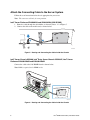
1
Intel® RAID Smart Battery AXXRSBBU3 Installation Guide Order Number: C95291-005 Disclaimer Information in this document is provided in connection with Intel® products. No license, express or implied, by estoppel or otherwise, to any intellectual property rights is granted by this document. Except as provided in Intel's Terms and Conditions of Sale for such products, Intel assumes no liability whatsoever, and Intel disclaims any express or implied warranty, relating to sale and/or use of Intel products including liability or warranties relating to fitness for a particular purpose, merchantability, or infringement of any patent, copyright or other intellectual property right. Intel products are not designed, intended or authorized for use in any medical, life saving, or life sustaining applications or for any other application in which the failure of the Intel product could create a situation where personal injury or death may occur. Intel may make changes to specifications and product descriptions at any time, without notice. Intel is a registered trademark of Intel Corporation or its subsidiaries in the United States and other countries. * Other names and brands may be claimed as the property of others. Copyright © 2005 - 2006 Intel Corporation. All Rights Reserved. ii Intel® RAID Smart Battery Installation Guide Important Safety Instructions Important Safety Instructions Read all caution and safety statements in this document before performing any of the instructions. See Intel Server Boards and Server Chassis Safety Information at http://support.intel.com/support/motherboards/server/sb/cs-010770.htm. Wichtige Sicherheitshinweise Lesen Sie zunächst sämtliche Warn- und Sicherheitshinweise in diesem Dokument, bevor Sie eine der Anweisungen ausführen. Beachten Sie hierzu auch die Sicherheitshinweise zu IntelServerplatinen und -Servergehäusen unter http://support.intel.com/support/motherboards/server/sb/cs-010770.htm. 重要安全指导 在执行任何指令之前,请阅读本文档中的所有注意事项及安全声明。 和/或http://support.intel.com/support/motherboards/server/sb/cs-010770.htm 上的 Intel Server Boards and Server Chassis Safety Information(《Intel 服务器主板与服务器机箱安全信息》)。 Important Safety InstructionsConsignes de sécurité Lisez attention toutes les consignes de sécurité et les mises en garde indiquées dans ce document avant de suivre toute instruction. Consultez Intel Server Boards and Server Chassis Safety Information rendez-vous sur le site http://support.intel.com/support/motherboards/server/sb/cs010770.htm. Instrucciones de seguridad importantes Lea todas las declaraciones de seguridad y precaución de este documento antes de realizar cualquiera de las instrucciones. Vea Intel Server Boards and Server Chassis Safety Information en http://support.intel.com/support/motherboards/server/sb/cs-010770.htm. Important Safety Instructions iii WARNINGS Server power on/off: The push-button on/off power switch on the front panel of the server does not turn off the AC power. To remove AC power from the server, you must unplug the AC power cord from either the power supply or wall outlet. Hazardous conditions—power supply: Hazardous voltage, current, and energy levels are present inside the power supply enclosure. There are no user-serviceable parts inside it; servicing should only be done by technically qualified personnel. Hazardous conditions—devices and cables: Hazardous electrical conditions may be present on power, telephone, and communication cables. Turn off the server and disconnect telecommunications systems, networks, modems, and the power cord attached to the server before opening it. Otherwise, personal injury or equipment damage can result. iv Intel® RAID Smart Battery Installation Guide Contents About the Intel® RAID Smart Battery ................................................................. 1 Installing the Hardware....................................................................................... 2 Prepare the Server.................................................................................................................. 2 ® Install the Intel RAID Smart Battery ....................................................................................... 2 Connect the Battery Cable ............................................................................................. 2 Connect the Clamshell to the Chassis ........................................................................... 3 Attach the Connecting Cable to the Server System ....................................................... 6 Finish Up the Hardware .......................................................................................................... 7 Contents v vi Intel® RAID Smart Battery Installation Guide About the Intel® RAID Smart Battery ® ® Intel RAID Controllers and Intel Integrated Server RAID Modules provide reliability, high performance, and fault-tolerant disk subsystem management. A complete fault-tolerant strategy requires protection for all data, including the unwritten cached data in the RAM cache. If power is lost, the data in RAM is lost. To avoid this data loss, a battery can be added to supply power to the RAID RAM during an AC power outage or if the AC power cord is removed. ® ® The Intel RAID Smart Battery (RSB) is a small battery pack accessory to the Intel Integrated ® Server RAID and the SCSI RAID on Motherboard (ROMB) solutions used on particular Intel Server Platforms. The Smart Battery preserves the contents of the RAID DIMM in the event of a power failure. Once power is restored, all of the preserved data in the RAID Cache DIMM is flushed to the RAID drives. The Smart Battery Circuit ensures that the backup battery is maintained at a full charge for optimal performance when it is activated. When activated, it provides backup power to the RAID DIMM for up to 64 hours. The Intel RAID Smart Battery is a compact package that contains the following components: Battery pack: The NiMH battery pack supplies power to the RAM if AC power is lost. The pack includes a Smart Refresh circuit and charger. The refresh circuit is based on the Texas Instruments* bq2060A SBS v1.1-compliant Gas Gauge IC. Software to monitor and inform the user of RSB activities is included. Plastic battery holder: The holder is designed to fit the following Intel ROMB-based server chassis and platforms: ® - Intel Entry Server Chassis SC5299-E ® - Intel Server Chassis SC5400 ® - Intel Server Platform SR1550AL with product code SR1550ALSAS ® - Intel Server Platform SR2500AL with product code SR2500ALSAS ® - Intel Server Platform SR4850HW4 with SCSI ROMB, product code SHW4UR/M ® - Intel Server Platform SR6850HW4 with SCSI ROMB, product code SHW6UR/M ® ® - Intel Server Platform SR4850HW4/M with Intel Integrated Server RAID (SAS), product code SHW4URM3SA ® ® - Intel Server Platform SR6850HW4/M with Intel Integrated Server RAID (SAS), product code SHW6URM3SA ® The battery pack fits inside the plastic clamshell, which in turn slides onto connectors in the server chassis. Connecting cables: 20-pin cables of multiple lengths are supplied in the kit to support various server configurations. These cables are connected between the battery pack and a connection ® point on the Intel Server System. 1 Installing the Hardware Prepare the Server 1. Observe all safety and ESD precautions at the beginning of this guide and in the documentation for your server board and chassis. 2. If your server system is running, power off all peripheral devices attached to the server, power down the server, and disconnect the AC power cord from the server. 3. Remove the chassis cover. See your server chassis documentation for instructions. Install the Intel® RAID Smart Battery Connect the Battery Cable 1. The clamshell is designed to be difficult to open to ensure the battery is secured. Observe the location of the closure tabs. See Letters “A” and “B” in Figure 1 . 2. Flex the inner edges of the clamshell to release the closure tabs. Caution: Do not exert excessive force when flexing the edges of the clamshell. Excessive pressure can break the clamshell. 3. Open the RAID Smart Battery clamshell. See Letter “C” in Figure 1. 4. Attach the connecting cable to the connector at the rear of the clamshell. See letter “D” in the figure. Use the cable appropriate for your server system: ® ® - Intel Server Platforms SR1550AL and SR2500AL that include Intel Integrated Server RAID (SAS): Use the 11-inch cable. ® - Intel Server Platform SR4850HW4 and SR6850HW4 with SCSI ROMB: Use the 11-inch cable. ® ® - Intel Server Platforms SR4850HW4/M and SR6850HW4/M with Intel Integrated Server RAID (SAS): Use the 27-inch cable. ® ® - Intel Server Chassis SC5400 and Intel Entry Server Chassis SC5299-E: Use the 27-inch cable. - Add-in SRCSAS controllers that use the Intel RAID Smart Battery: Use the 20-inch cable. 2 Intel® RAID Smart Battery Installation Guide A C D B AF000482 Figure 1. Connecting Battery Cable Connect the Clamshell to the Chassis ® ® The Intel RAID Smart Battery SXXRSBBU3 is designed for easy attachment to either an Intel pedestal or rack chassis. Follow the set of instructions below that is appropriate for your server. If you are installing this component into a third-party chassis, you will first need to install an attachment mechanism, such as industrial-grade Velcro*. See your server chassis documentation or discuss an appropriate attachment mechanism with your server chassis manufacturer to ensure the attachment mechanism complies with the requirements of the chassis. 3 ® ® ® Intel Server Chassis SC5400, Intel Entry Server Chassis SC5299-E, Intel Server Platforms SR4850HW4, SR6850HW4, SR4850HW4/M, and SR6850HW4/M 1. Locate the installation clips inside the chassis. They are at the left side of the chassis, near the rear. 2. Align the tabs on the clamshell with the slots on the chassis. TP01407 Figure 2. Aligning Tabs to Slots 3. Slide the clamshell toward the front of the system until the tabs engage in the chassis (see Figure 3). TP01408 Figure 3. Engaging Tabs in Slots 4 Intel® RAID Smart Battery Installation Guide ® Intel Server Platforms SR1550AL and SR2500AL 1. Clips are located on the inside floor of the chassis, at the left side, near the front of the chassis, near the power supply. 2. Align the tabs on the clamshell with the slots on the chassis. 3. Slide the clamshell toward the rear of the system until the tabs engage in the chassis (see Figure 4). AF000480 Figure 4. Engaging Tabs in Slots 5 Attach the Connecting Cable to the Server System Follow the set of instructions below that is appropriate for your server. Note: The connector will only fit in one position. ® Intel Server Platforms SR4850HW4 and SR6850HW4 (SCSI ROMB) 1. Route the cable through the cable holder as shown by Letter “A” of Figure 5. 2. Connect the cable to the main board, as shown below. A B TP01409 Figure 5. Routing and Connecting the Cable inside the Chassis ® ® ® Intel Server Chassis SC5400, Intel Entry Server Chassis SC5299-E, Intel Server Platforms SR4850HW4/M and SR6850HW4/M Connect the cable to the SAS ROMB board as shown below. Note: RAM is required in the DIMM socket. AF000254 Figure 6. Routing and Connecting the Cable inside the Chassis 6 Intel® RAID Smart Battery Installation Guide ® Intel Server Platforms SR1550AL and SR2500AL Connect the cable to the midplane SAS ROMB board as shown below. AF000483 Figure 7. Routing and Connecting the Cable inside the Chassis Finish Up the Hardware 1. Reinstall any components inside of the server chassis that you needed to remove. See your server board or chassis documentation for instructions. 2. Install the server chassis cover and connect the AC power supply. 7