1
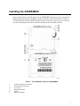
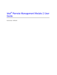
Intel® RAID Smart Battery
AXXRSBBU6
User’s Guide
Order Number: E33722-001
Warranty Notice: Adding a battery on an Intel RAID controller will limit the warranty of this product. Returns determined to
be caused by battery installation damage, stripped screws, or other damage resulting from the battery installation will not be
covered. ESD damage to the board will also not be covered by the warranty.
The warranty on the AXXRSBBU6 is 1 year.
Disclaimer
Information in this document is provided in connection with Intel® products. No license, express or implied, by estoppel or
otherwise, to any intellectual property rights is granted by this document. Except as provided in Intel's Terms and Conditions
of Sale for such products, Intel assumes no liability whatsoever, and Intel disclaims any express or implied warranty, relating
to sale and/or use of Intel products including liability or warranties relating to fitness for a particular purpose, merchantability,
or infringement of any patent, copyright or other intellectual property right. Intel products are not designed, intended or
authorized for use in any medical, life saving, or life sustaining applications or for any other application in which the failure of
the Intel product could create a situation where personal injury or death may occur. Intel may make changes to
specifications and product descriptions at any time, without notice.
Intel is a registered trademark of Intel Corporation or its subsidiaries in the United States and other countries.
* Other names and brands may be claimed as the property of others.
Copyright © 2008 Intel Corporation. All Rights Reserved.
Copyright © 2008 by LSI Logic Corporation. All rights reserved
ii
Contents
List of Figures..................................................................................................... iv
List of Tables ...................................................................................................... iv
About the Intel® RAID Smart Battery ...................................................................i
Installing the AXXRSBBU6 ................................................................................. 3
Important Pre-installation Considerations ...................................................................... 4
Step-by-step AXXRSBBU6 Installation .......................................................................... 4
Monitoring Battery Backup ................................................................................ 7
Monitoring BBUs with the RAID BIOS Configuration Utility............................................ 7
Using Intel® RAID Web Console 2 ................................................................................. 8
Replacing Battery Backup Units........................................................................ 9
Disposing of Battery Backup Units ................................................................................. 9
Battery Backup Unit Specifications................................................................. 10
Battery Life and Data Retention Time .......................................................................... 10
iii
List of Figures
Figure 1. Top and Bottom View of the AXXRSBBU6...................................................................3
Figure 2. Battery alignment on the add-in Intel® RAID Controllers ..............................................5
Figure 3. Battery board mounting on RAID controller board........................................................5
Figure 4. Reinserting an add-in RAID Controller .........................................................................6
Figure 5. Battery monitoring with the RAID BIOS Utility ..............................................................7
Figure 6. BBU information in RWC2 ............................................................................................8
List of Tables
Table 1. Battery Backup Unit Specifications ..............................................................................10
iv
About the Intel® RAID Smart Battery
Intel® RAID Controllers and Intel® Integrated Server RAID Modules provide reliability, high
performance, and fault-tolerant disk subsystem management. A complete fault-tolerant strategy
requires protection for all data, including the unwritten cached data in the RAM cache. If power is
lost, the data in RAM is lost. To avoid this data loss, a battery can be added to supply power to the
RAID RAM during an AC power outage or if the AC power cord is removed.
A battery backup unit protects the integrity of the cached data on Intel RAID controllers by
providing backup power if there is a complete AC power failure or a brief power outage. The Intel
RSBBUs provide an inexpensive alternative to using an uninterruptible power supply (UPS) or act
as a second level of fault tolerance when used in conjunction with a UPS.
The cache memory available on Intel controllers can improve overall system performance. Writing
data to the controller’s cache memory is much faster than writing it to a storage device. Write
operations appear to complete very quickly at the software application level. The Intel RAID
controller then writes the cached data to the storage device when system activity is low or when the
cache is getting full. The risk of using write-back cache is that the cached data can be lost if the AC
power fails before it has been written to the storage device. This risk factor is eliminated when the
Intel RAID controller has an onboard BBU.
The Intel RSBBUs monitor the voltage level of the DRAM modules installed on the Intel RAID
controller. If the voltage drops below a predefined level, the battery backup module switches the
memory power source from the Intel RAID controller to the battery pack attached to the Intel RAID
Smart Battery Backup Unit (RSBBU). As long as the voltage level stays below the predefined
value, the Intel RSBBU provides power for memory. If the voltage level returns to an acceptable
level, the RSBBU switches the power source back to the Intel RAID controller, and all pending
writes to storage devices are completed with no data loss.
A smart battery backup unit (BBU) has built-in functionality to charge the battery pack
automatically and to communicate battery status information such as voltage, temperature, and
current to the host computer system.
The AXXRSBBU6 is a smart battery back up module using LiON technology that is compatible
with a backup auxiliary power source. Battery charging and recharging take place automatically.
The AXXRSBBU6, which features LiON battery cell technology, mounts directly to the following
Intel® RAID Controllers using a small board-to-board connector (daughtercard):
1
•
Intel® RAID Controller SRCSASBB8I
•
Intel® RAID Controller SRCSASLS4I
Intel® RAID Smart Battery User’s Guide
Important Safety Instructions
Read all caution and safety statements in this document before performing any of the instructions.
See Intel Server Boards and Server Chassis Safety Information at
http://support.intel.com/support/motherboards/server/sb/cs-010770.htm.
Wichtige Sicherheitshinweise
Lesen Sie zunächst sämtliche Warn- und Sicherheitshinweise in diesem Dokument, bevor Sie eine
der Anweisungen ausführen. Beachten Sie hierzu auch die Sicherheitshinweise zu IntelServerplatinen und -Servergehäusen unter
http://support.intel.com/support/motherboards/server/sb/cs-010770.htm.
重要安全指导
在执行任何指令之前,请阅读本文档中的所有注意事项及安全声明。
和/或http://support.intel.com/support/motherboards/server/sb/cs-010770.htm 上的 Intel
Server Boards and Server Chassis Safety Information(《Intel
服务器主板与服务器机箱安全信息》)。
Important Safety InstructionsConsignes de sécurité
Lisez attention toutes les consignes de sécurité et les mises en garde indiquées dans ce document
avant de suivre toute instruction. Consultez Intel Server Boards and Server Chassis Safety
Information rendez-vous sur le site http://support.intel.com/support/motherboards/server/sb/cs010770.htm.
Instrucciones de seguridad importantes
Lea todas las declaraciones de seguridad y precaución de este documento antes de realizar
cualquiera de las instrucciones. Vea Intel Server Boards and Server Chassis Safety Information en
http://support.intel.com/support/motherboards/server/sb/cs-010770.htm.
WARNINGS
Server power on/off: The push-button on/off power switch on the front
panel of the server does not turn off the AC power. To remove AC power
from the server, you must unplug the AC power cord from either the power
supply or wall outlet.
• Hazardous conditions—power supply: Hazardous voltage, current, and energy levels
are present inside the power supply enclosure. There are no user-serviceable parts
inside it; servicing should only be done by technically qualified personnel.
2
Intel® RAID Smart Battery User’s Guide
Installing the AXXRSBBU6
Figure 1 displays the top and bottom views of the AXXRSBBU6. The battery pack is mounted on a
daughtercard which mounts to the RAID controller. Take note of the location of the J2 connector
(5) which plugs into the Intel® RAID Controller and the 3 standoffs (2) and 6 screws (3). Only the
top side of the daughtercard will be visible after installation onto the RAID controller.
Figure 1. Top and Bottom View of the AXXRSBBU6
1.
2.
3.
4.
5.
6.
J4 battery pack harness connector
J5 board-to-board connector
J2 connector
Battery pack harness
Screws
Spacers (stand-offs)
3
Important Pre-installation Considerations
Warning: Always ground yourself and/or use a ground strap before touching the RAID controller
or the RSBBU. Perform all installation work at an ESD-safe workstation. Use an ESD-safe Phillips
screwdriver set to a maximum torque of 2.25 inch pounds, and be sure the screwdriver is centered
in the screw to avoid damaging the screw head. If you exceed the maximum torque specification,
you may damage the board, connectors, or screws, and you will void the warranty of the board.
The batteries in the RSBBUs must recharge for at least six hours during fast charge under normal
operating conditions.
To protect your data, Intel recommends that you set the RAID controller Write Policy to writethrough until the battery unit is fully charged. When the battery unit is charged, you can change the
Write Policy to write-back to take advantage of the performance improvements of data caching.
The maximum ambient temperature for the battery pack is 45°C. Note: The temperature of the
battery pack is generally 15–20 degrees higher than the ambient temperature during fast charge.
Therefore, to complete the fast charge cycle, ambient temperature should be less than 45°C. If the
ambient temperature exceeds 45°C, the fast charge cycle will terminate prematurely, thus
preventing the battery pack from reaching a fully charged state.
Step-by-step AXXRSBBU6 Installation
Follow the steps in this section to install the AXXRSBBU6 on the Intel® RAID Controller
SRCSASBB8I or SRCSASLS4I.
A. If the RAID controller is already installed in a computer, follow these steps to remove it before
you install the AXXRSBBU6:
1. Shut down the computer, turn off the power, and unplug the power cord(s).
2. Remove the cover from the computer and ground yourself before touching the RAID
controller. Carefully unplug all cables going to the RAID controller. On the data cables,
depress the silver spring at the connector end to make sure the 2 tiny catches release.
3. Following the instructions in User’s Guide for your server, carefully remove the RAID
controller from its slot. On the Intel® Server Platform S7000FC4UR, you must remove
the processor air baffle and push back on the guide latch while pulling up on the riser
card.
4. Place the RAID controller on a flat, clean, static-free surface.
B. Follow these steps to install the AXXRSBBU6 on the RAID Controller.
1. Ground yourself, and remove the AXXRSBBU6 from the package.
2. Insert the battery pack harness connector (number 4 in Figure 1) at the end of the colored
wires into the 5-pin J4 connector (number 1 in Figure 1) on the backside of the
AXXRSBBU6.
3. Make sure the 3 standoffs and 6 screws and the Phillips screwdriver are easily available
during the following steps.
4
4. Remove the protective metal cover from the battery connector on the RAID controller
card. (J10 on the Intel® SRCSASBB8I and Intel® SRCSASLS4I.)
5. On the Intel® RAID Controller SRCSASBB8I and the Intel® RAID Controller
SRCSASLS4I, place the RAID controller with the components facing up.
Figure 2. Battery alignment on the add-in Intel® RAID Controllers
6. Hold the AXXRSBBU6 so that the battery side is up and the three screw holes align.
Figure 3. Battery board mounting on RAID controller board
7. Place the three standoffs (#6 in Figure 1) between the two cards in the three screw holes.
8. Carefully press the AXXRSBBU6 onto the RAID controller, so that the two connectors
shown in Figure 3 are firmly joined.
•
On the Intel® RAID Controller SRCSASBB8I and the Intel® SRCSASLS4I, use the
J10 connector.
9. Secure the AXXRSBBU6 to the RAID controller with the 6 provided Phillips (2-56)
screws (#5 in Figure 1). The standoffs are threaded at both ends and a 2-56 screw goes
into each end. (Place 3 in from the battery side and 3 in from the RAID controller side.)
5
Caution: Center the screwdriver carefully to avoid stripping the
screwhead. Do not over-tighten the screws. The maximum recommended
torque is 2.25 inch pounds.
C. Place the Intel® RAID Controller back into the server
1. Align the RAID controller with the PCI Express* slot.
2. Press down gently, but firmly, to ensure that the RAID controller is properly seated in the
slot. The bottom edge of the RAID controller must be flush with the slot.
Caution: Never apply pressure to the AXXRSBBU6 when you insert the
RAID controller. Instead, press down only on the top edge of the RAID
controller.
Figure 4. Reinserting an add-in RAID Controller
3. Attach the cables, as needed, to the connectors on the Intel® RAID controller.
•
For the Intel® Server Platform S7000FC4UR only: Install the processor air baffle.
4. Replace the computer cover and reattach the power cord(s).
.
6
Monitoring Battery Backup
Multiple utilities are available to display and configure BBU information including recharge count.
When you replace a BBU, you should reset this counter to zero. Intel recommends that you replace
the BBU once per year or after 500 recharge cycles, whichever comes first.
Note: This chapter describes only the BBU-related features of the Intel utility programs. For
complete information on these utilities, see the Intel® RAID Software User’s Guide.
Monitoring BBUs with the RAID BIOS Configuration Utility
The Intel® RAID BIOS Console configures disk arrays and logical drives. It is independent of the
operating system and accessed at server start up by pressing <Cntrl> <G>
To view the BBU information, follow these steps:
1. At boot, press <Cntrl><G> when prompted.
2. In the RAID BIOS Console, choose “Adapter Properties” on the main menu.
3. Click Next to view the second Adapter Properties screen.
4. In the Battery Backup field at the top left of the screen, click the word “Present”.
Figure 5. Battery monitoring with the RAID BIOS Utility
7
Most of the Battery Module properties are view-only. In the lower right panel of the RAID BIOS
Console there are two properties that can be changed. (Intel recommends that you leave these
properties at their default settings.)
•
Learn Delay Interval – default 30 days
•
Auto Learn Mode – default Auto
Note: The learning cycle is a battery calibration operation performed by the controller periodically
to determine the condition of the battery.
Using Intel® RAID Web Console 2
The status of all BBUs connected to controllers in the server is visible in Intel® RAID Web Console
2 by selecting the Physical tab in the left panel. To see the battery, select the Controller. The
Battery Backup Unit will appear as the last item on the list under that controller. An icon (small
rectangle or red dot) will appear in the left pane to indicate the BBU status. The rectangle indicates
normal operation, the red dot indicates the BBU has failed.
Figure 6. BBU information in RWC2
The BBU properties include the following:
•
The number of times the BBU has been recharged (Cycle Count)
•
The full capacity of the BBU, plus the percentage of its current state of charge, and the
estimated time until it will be depleted
8
•
The current BBU temperature, voltage, current, and remaining capacity
•
The estimated time until the battery is fully charged (only if the battery is charging)
Replacing Battery Backup Units
Intel recommends that you replace BBUs once a year or after 500 recharging cycles, whichever
comes first. The warranty on the battery pack is for one year. After you install a new BBU, use one
of the Intel configuration utilities to reset the battery recharge cycle counter to zero. For
instructions, see Chapter 3, “Monitoring BBUs with the Intel Configuration Utilities.”
Disposing of Battery Backup Units
WARNING: Do not damage the battery pack in any way. Toxic
chemicals can be released if it is damaged.
The material in the battery pack contains heavy metals that can contaminate the environment.
Federal, state, and local regulations prohibit the disposal of rechargeable batteries in public
landfills. Be sure to recycle the old battery packs properly. Intel reminds you that you must comply
with all applicable battery disposal and hazardous material handling laws and regulations in the
country or other jurisdiction where you are using the BBU.
9
Battery Backup Unit Specifications
Table 1. Battery Backup Unit Specifications
Battery Technology
LiON (Lithium ION) 1 cell
Battery Operating Environment
10–45°C ambient temperature
20% to 80% humidity non-condensing
Battery Storage Temperature
Depends on storage time,:< 30 days: 0–50 °C
30–90 days: 0–40 °C ‘; > 90 days: 0–30 °C
Fast Charge Current
500mAH using charge circuitry card
Battery Voltage
Nominal OCV: 3.7 V
Mechanical
2.611 inches x 2.122 inches
Battery Capacity
700 mAH
Memory Technology
DDR2 SDRAM (1.8 V)
Battery Charge Time
Typical: ~3 hours to charge from 1.8V OCV to 3.7V OCV
Completely depleted: 8 hours
Battery Shelf Life
1 year
Battery Operational Life
Intel provides a 1 year warranty on the AXXRSBBU6.
Supported Cache Memory
128 - 512 Mbytes
Memory
DDR2 SDRAM 667 MHz (1.8V), max 40-bit bus width
MTBF (Electrical Components)
2,490,772 hours at 40° C
Smart Battery Monitoring
Temp monitoring via I2C interface. Supports v1.1 “Smart Battery
System Manager”
Auxiliary Power
Ability to detect the presence of an external auxiliary power source.
Circuitry automatically chooses aux power, defers discharge until aux
power is removed or exhausted. Auxpower increases the DRT ratings
Battery Life and Data Retention Time
The Intel utilities display a counter showing the number of times a BBU has been recharged. When
you replace a BBU, you should run the utility program and reset this counter to zero for the new
BBU. Intel recommends that you replace the battery pack on the BBU once a year or after 500
recharging cycles, whichever comes first. The warranty on the battery pack is for one year.
The data retention time is 72 hours (low power) if using the RAM shown below. This rating is
approximate and can vary based on battery load, ambient temperature, and number of discharge
cycles associated with the battery.
•
256 Mb using (3) 64Mx16 DDR2
•
128 Mb using (3) 32Mx16 DDR2
10