1
Cisco Wireless ISR and HWIC Access Point
Configuration Guide
December 2006
Corporate Headquarters
Cisco Systems, Inc.
170 West Tasman Drive
San Jose, CA 95134-1706
USA
http://www.cisco.com
Tel: 408 526-4000
800 553-NETS (6387)
Fax: 408 526-4100
Text Part Number: 0L-6415-04
THE SPECIFICATIONS AND INFORMATION REGARDING THE PRODUCTS IN THIS MANUAL ARE SUBJECT TO CHANGE WITHOUT NOTICE. ALL
STATEMENTS, INFORMATION, AND RECOMMENDATIONS IN THIS MANUAL ARE BELIEVED TO BE ACCURATE BUT ARE PRESENTED WITHOUT
WARRANTY OF ANY KIND, EXPRESS OR IMPLIED. USERS MUST TAKE FULL RESPONSIBILITY FOR THEIR APPLICATION OF ANY PRODUCTS.
THE SOFTWARE LICENSE AND LIMITED WARRANTY FOR THE ACCOMPANYING PRODUCT ARE SET FORTH IN THE INFORMATION PACKET THAT
SHIPPED WITH THE PRODUCT AND ARE INCORPORATED HEREIN BY THIS REFERENCE. IF YOU ARE UNABLE TO LOCATE THE SOFTWARE LICENSE
OR LIMITED WARRANTY, CONTACT YOUR CISCO REPRESENTATIVE FOR A COPY.
The Cisco implementation of TCP header compression is an adaptation of a program developed by the University of California, Berkeley (UCB) as part of UCB’s public
domain version of the UNIX operating system. All rights reserved. Copyright © 1981, Regents of the University of California.
NOTWITHSTANDING ANY OTHER WARRANTY HEREIN, ALL DOCUMENT FILES AND SOFTWARE OF THESE SUPPLIERS ARE PROVIDED “AS IS” WITH
ALL FAULTS. CISCO AND THE ABOVE-NAMED SUPPLIERS DISCLAIM ALL WARRANTIES, EXPRESSED OR IMPLIED, INCLUDING, WITHOUT
LIMITATION, THOSE OF MERCHANTABILITY, FITNESS FOR A PARTICULAR PURPOSE AND NONINFRINGEMENT OR ARISING FROM A COURSE OF
DEALING, USAGE, OR TRADE PRACTICE.
IN NO EVENT SHALL CISCO OR ITS SUPPLIERS BE LIABLE FOR ANY INDIRECT, SPECIAL, CONSEQUENTIAL, OR INCIDENTAL DAMAGES, INCLUDING,
WITHOUT LIMITATION, LOST PROFITS OR LOSS OR DAMAGE TO DATA ARISING OUT OF THE USE OR INABILITY TO USE THIS MANUAL, EVEN IF CISCO
OR ITS SUPPLIERS HAVE BEEN ADVISED OF THE POSSIBILITY OF SUCH DAMAGES.
CCVP, the Cisco Logo, and the Cisco Square Bridge logo are trademarks of Cisco Systems, Inc.; Changing the Way We Work, Live, Play, and Learn is a service mark of
Cisco Systems, Inc.; and Access Registrar, Aironet, BPX, Catalyst, CCDA, CCDP, CCIE, CCIP, CCNA, CCNP, CCSP, Cisco, the Cisco Certified Internetwork Expert logo,
Cisco IOS, Cisco Press, Cisco Systems, Cisco Systems Capital, the Cisco Systems logo, Cisco Unity, Enterprise/Solver, EtherChannel, EtherFast, EtherSwitch, Fast Step,
Follow Me Browsing, FormShare, GigaDrive, GigaStack, HomeLink, Internet Quotient, IOS, iPhone, IP/TV, iQ Expertise, the iQ logo, iQ Net Readiness Scorecard, iQuick
Study, LightStream, Linksys, MeetingPlace, MGX, Networking Academy, Network Registrar, Packet, PIX, ProConnect, RateMUX, ScriptShare, SlideCast, SMARTnet,
StackWise, The Fastest Way to Increase Your Internet Quotient, and TransPath are registered trademarks of Cisco Systems, Inc. and/or its affiliates in the United States and
certain other countries.
All other trademarks mentioned in this document or Website are the property of their respective owners. The use of the word partner does not imply a partnership relationship
between Cisco and any other company. (0612R)
Cisco Wireless ISR and HWIC Access Point Configuration Guide
Copyright © 2006 Cisco Systems, Inc.
All rights reserved.
CONTENTS
Preface
9
Audience
Purpose
9
9
Organization
10
Conventions
10
Related Publications
12
Obtaining Documentation 13
Cisco.com 13
Product Documentation DVD 14
Ordering Documentation 14
Documentation Feedback
14
Cisco Product Security Overview 15
Reporting Security Problems in Cisco Products
15
Obtaining Technical Assistance 16
Cisco Technical Support & Documentation Website
Submitting a Service Request 16
Definitions of Service Request Severity 17
Obtaining Additional Publications and Information
CHAPTER
1
Overview
16
17
1
Wireless Device Management
1
Network Configuration Example 2
Root Unit on a Wired LAN 2
Features
3
5
CHAPTER
2
Configuring Radio Settings
1
Enabling the Radio Interface
Roles in Radio Network
2
2
Configuring Network or Fallback Role 3
Bridge Features Not Supported 4
Sample Bridging Configuration 4
Universal Client Mode
7
Cisco Wireless Router and HWIC Configuration Guide
OL-6415-04
3
Contents
Configuring Universal Client Mode
Configuring Radio Data Rates
7
10
Configuring Radio Transmit Power 12
Limiting the Power Level for Associated Client Devices
13
Configuring Radio Channel Settings 14
DFS Automatically Enabled on Some 5-GHz Radio Channels
Enabling and Disabling World Mode
19
20
Enabling and Disabling Short Radio Preambles
Configuring Transmit and Receive Antennas
21
22
Disabling and Enabling Access Point Extensions
23
Configuring the Ethernet Encapsulation Transformation Method
23
Enabling and Disabling Reliable Multicast to Workgroup Bridges
Enabling and Disabling Public Secure Packet Forwarding
Configuring Protected Ports 26
Configuring Beacon Period and DTIM
27
27
Configuring Fragmentation Threshold
28
Enabling Short Slot Time for 802.11g Radios
Performing a Carrier Busy Test
CHAPTER
3
Configuring Multiple SSIDs
25
26
Configuring RTS Threshold and Retries
Configuring Maximum Data Retries
28
29
1
Understanding Multiple SSIDs 2
SSID Configuration Methods Supported by Cisco IOS Releases
Configuring Multiple SSIDs 3
Creating an SSID Globally 3
Using a RADIUS Server to Restrict SSIDs
6
Enabling MBSSID and SSIDL at the same time 7
Sample Configuration for Enabling MBSSID and SSIDL
4
Configuring an Access Point as a Local Authenticator
Understand Local Authentication
2
5
Configuring Multiple Basic SSIDs 6
Requirements for Configuring Multiple BSSIDs
Guidelines for Using Multiple BSSIDs 6
CHAPTER
24
8
1
2
Configure a Local Authenticator 2
Guidelines for Local Authenticators
3
Cisco Wireless Router and HWIC Configuration Guide
4
OL-6415-04
Contents
Configuration Overview 3
Configuring the Local Authenticator Access Point 3
Configuring Other Access Points to Use the Local Authenticator 8
Configuring EAP-FAST Settings 9
Limiting the Local Authenticator to One Authentication Type 11
Unblocking Locked Usernames 11
Viewing Local Authenticator Statistics 11
Using Debug Messages 12
12
CHAPTER
5
Configuring Encryption Types
1
Understand Encryption Types
2
Configure Encryption Types 3
Creating WEP Keys 3
Creating Cipher Suites 5
Enabling and Disabling Broadcast Key Rotation
Security Type in Universal Client Mode 8
CHAPTER
6
Configuring Authentication Types
7
1
Understand Authentication Types 2
Open Authentication to Access Point 2
Shared Key Authentication to Access Point 3
EAP Authentication to Network 4
MAC Address Authentication to the Network 5
Combining MAC-Based, EAP, and Open Authentication 6
Using WPA Key Management 6
Software and Firmware Requirements for WPA and WPA-TKIP
Configure Authentication Types 9
Assigning Authentication Types to an SSID 9
Configuring Authentication Holdoffs, Timeouts, and Intervals
Matching Access Point and Client Device Authentication Types
CHAPTER
7
Configuring RADIUS Servers
8
15
16
1
Configuring and Enabling RADIUS 2
Understanding RADIUS 2
RADIUS Operation 3
Configuring RADIUS 4
Displaying the RADIUS Configuration
17
Cisco Wireless Router and HWIC Configuration Guide
OL-6415-04
5
Contents
RADIUS Attributes Sent by the Access Point
CHAPTER
Configuring VLANs
8
18
1
Understanding VLANs 2
Related Documents 3
Incorporating Wireless Devices into VLANs
4
Configuring VLANs 4
Configuring a VLAN 5
Assigning Names to VLANs 7
Using a RADIUS Server to Assign Users to VLANs 7
Viewing VLANs Configured on the Access Point 8
VLAN Configuration Example
CHAPTER
Configuring QoS
9
9
1
Understanding QoS for Wireless LANs 2
QoS for Wireless LANs Versus QoS on Wired LANs
Impact of QoS on a Wireless LAN 2
Precedence of QoS Settings 3
Using Wi-Fi Multimedia Mode 4
2
Configuring QoS 4
Configuration Guidelines 5
Adjusting Radio Access Categories 5
Disabling IGMP Snooping Helper 6
Sample Configuration Using the CLI 6
APPENDIX
A
Channel Settings
1
IEEE 802.11b (2.4-GHz Band)
1
IEEE 802.11g (2.4-GHz Band)
2
IEEE 802.11a (5-GHz Band)
APPENDIX
B
Protocol Filters
APPENDIX
C
Supported MIBs
MIB List
2
1
1
1
Using FTP to Access the MIB Files
APPENDIX
D
Error and Event Messages
2
1
How to Read System Messages
1
Cisco Wireless Router and HWIC Configuration Guide
6
OL-6415-04
Contents
Message Traceback Reports
2
Association Management Messages
802.11 Subsystem Messages
Local Authenticator Messages
2
3
12
GLOSSARY
INDEX
Cisco Wireless Router and HWIC Configuration Guide
OL-6415-04
7
Contents
Cisco Wireless Router and HWIC Configuration Guide
8
OL-6415-04
Preface
The Preface provides information on the following topics:
•
Audience
•
Purpose
•
Organization
•
Related Publications
•
Obtaining Documentation
Audience
This guide is for the networking professional who installs and manages Cisco stationary routers with
wireless capabilities. You should have experience working with the Cisco IOS software and be familiar
with the concepts and terminology of wireless LANs.
This document provides information for the following interfaces:
•
Access Point High-speed WAN Interface Card (AP HWIC)
•
Cisco 800 series routers with wireless capabilities
•
Cisco 1800 series routers with wireless capabilities.
Purpose
This guide provides the information you need to install and configure your Cisco wireless device, for
example, AP HWIC, Cisco 800 series and Cisco 1800 series routers. This guide provides procedures for
using the Cisco IOS software commands that have been created or changed for use with the wireless
device. It does not provide detailed information about these commands. For information about the
standard Cisco IOS software commands, see the Cisco IOS software documentation set available from
the Cisco.com home page at Service and Support > Technical Documents. On the Cisco Product
Documentation home page, select Release 12.4 from the Cisco IOS Software drop-down list.
Cisco Wireless ISR and HWIC Access Point Configuration Guide
OL-6415-04
9
Preface
Organization
Organization
This guide consists of the following chapters:
Chapter 1, “Overview,” lists the software and hardware features of the wireless device and describes the
role of the wireless device in your network.
Chapter 2, “Configuring Radio Settings,” describes how to configure settings for the wireless device
radio such as the role in the radio network, data rates, transmit power, channel settings, and others.
Chapter 3, “Configuring Multiple SSIDs,” describes how to configure and manage multiple service set
identifiers (SSIDs) and multiple basic SSIDs (BSSIDs) on your wireless device. You can configure up
to 16 SSIDs and 16 BSSIDs on your wireless device and assign different configuration settings to each.
Chapter 4, “Configuring an Access Point as a Local Authenticator,” describes how to configure the
wireless device to act as a local RADIUS server for your wireless LAN. If the WAN connection to your
main RADIUS server fails, the wireless device acts as a backup server to authenticate wireless devices.
Chapter 5, “Configuring Encryption Types,” describes how to configure the cipher suites required to use
authenticated key management, Wired Equivalent Privacy (WEP), and WEP features.
Chapter 6, “Configuring Authentication Types,” describes how to configure authentication types on the
wireless device. Client devices use these authentication methods to join your network.
Chapter 7, “Configuring RADIUS Servers,” describes how to enable and configure the RADIUS, which
provides detailed accounting information and flexible administrative control over authentication and
authorization processes.
Chapter 8, “Configuring VLANs,” describes how to configure your wireless device to interoperate with
the VLANs set up on your wired LAN.
Chapter 9, “Configuring QoS,” describes how to configure quality of service (QoS) on your wireless
device. With this feature, you can provide preferential treatment to certain traffic at the expense of
others.
Appendix A, “Channel Settings,” lists the wireless device radio channels and the maximum power levels
supported by the world’s regulatory domains.
Appendix B, “Protocol Filters,” lists some of the protocols that you can filter on the wireless device.
Appendix C, “Supported MIBs,” lists the Simple Network Management Protocol (SNMP) Management
Information Bases (MIBs) that the wireless device supports for this software release.
Appendix D, “Error and Event Messages,” lists the CLI error and event messages and provides an
explanation and recommended action for each message.
Conventions
This publication uses these conventions to convey instructions and information:
Command descriptions use these conventions:
•
Commands and keywords are in boldface text.
•
Arguments for which you supply values are in italic.
•
Square brackets ([ ]) mean optional elements.
•
Braces ({ }) group required choices, and vertical bars ( | ) separate the alternative elements.
•
Braces and vertical bars within square brackets ([{ | }]) mean a required choice within an optional
element.
Cisco Wireless ISR and HWIC Access Point Configuration Guide
10
OL-6415-04
Preface
Conventions
Interactive examples use these conventions:
•
Terminal sessions and system displays are in screen font.
•
Information you enter is in boldface screen font.
•
Nonprinting characters, such as passwords or tabs, are in angle brackets (< >).
Notes, cautions, and timesavers use these conventions and symbols:
Tip
Means the following will help you solve a problem. The tips information might not be troubleshooting
or even an action, but could be useful information.
Note
Means reader take note. Notes contain helpful suggestions or references to materials not contained in
this manual.
Caution
Warning
Waarschuwing
Means reader be careful. In this situation, you might do something that could result equipment damage
or loss of data.
This warning symbol means danger. You are in a situation that could cause bodily injury. Before you
work on any equipment, be aware of the hazards involved with electrical circuitry and be familiar
with standard practices for preventing accidents. (To see translations of the warnings that appear
in this publication, refer to the appendix “Translated Safety Warnings.”)
Dit waarschuwingssymbool betekent gevaar. U verkeert in een situatie die lichamelijk letsel kan
veroorzaken. Voordat u aan enige apparatuur gaat werken, dient u zich bewust te zijn van de bij
elektrische schakelingen betrokken risico’s en dient u op de hoogte te zijn van standaard
maatregelen om ongelukken te voorkomen. (Voor vertalingen van de waarschuwingen die in deze
publicatie verschijnen, kunt u het aanhangsel “Translated Safety Warnings” (Vertalingen van
veiligheidsvoorschriften) raadplegen.)
Varoitus
Tämä varoitusmerkki merkitsee vaaraa. Olet tilanteessa, joka voi johtaa ruumiinvammaan. Ennen
kuin työskentelet minkään laitteiston parissa, ota selvää sähkökytkentöihin liittyvistä vaaroista ja
tavanomaisista onnettomuuksien ehkäisykeinoista. (Tässä julkaisussa esiintyvien varoitusten
käännökset löydät liitteestä "Translated Safety Warnings" (käännetyt turvallisuutta koskevat
varoitukset).)
Attention
Ce symbole d’avertissement indique un danger. Vous vous trouvez dans une situation pouvant
entraîner des blessures. Avant d’accéder à cet équipement, soyez conscient des dangers posés par
les circuits électriques et familiarisez-vous avec les procédures courantes de prévention des
accidents. Pour obtenir les traductions des mises en garde figurant dans cette publication, veuillez
consulter l’annexe intitulée « Translated Safety Warnings » (Traduction des avis de sécurité).
Cisco Wireless ISR and HWIC Access Point Configuration Guide
OL-6415-04
11
Preface
Related Publications
Warnung
Dieses Warnsymbol bedeutet Gefahr. Sie befinden sich in einer Situation, die zu einer
Körperverletzung führen könnte. Bevor Sie mit der Arbeit an irgendeinem Gerät beginnen, seien Sie
sich der mit elektrischen Stromkreisen verbundenen Gefahren und der Standardpraktiken zur
Vermeidung von Unfällen bewußt. (Übersetzungen der in dieser Veröffentlichung enthaltenen
Warnhinweise finden Sie im Anhang mit dem Titel “Translated Safety Warnings” (Übersetzung der
Warnhinweise).)
Avvertenza
Questo simbolo di avvertenza indica un pericolo. Si è in una situazione che può causare infortuni.
Prima di lavorare su qualsiasi apparecchiatura, occorre conoscere i pericoli relativi ai circuiti
elettrici ed essere al corrente delle pratiche standard per la prevenzione di incidenti. La traduzione
delle avvertenze riportate in questa pubblicazione si trova nell’appendice, “Translated Safety
Warnings” (Traduzione delle avvertenze di sicurezza).
Advarsel
Dette varselsymbolet betyr fare. Du befinner deg i en situasjon som kan føre til personskade. Før du
utfører arbeid på utstyr, må du være oppmerksom på de faremomentene som elektriske kretser
innebærer, samt gjøre deg kjent med vanlig praksis når det gjelder å unngå ulykker. (Hvis du vil se
oversettelser av de advarslene som finnes i denne publikasjonen, kan du se i vedlegget "Translated
Safety Warnings" [Oversatte sikkerhetsadvarsler].)
Aviso
Este símbolo de aviso indica perigo. Encontra-se numa situação que lhe poderá causar danos
fisicos. Antes de começar a trabalhar com qualquer equipamento, familiarize-se com os perigos
relacionados com circuitos eléctricos, e com quaisquer práticas comuns que possam prevenir
possíveis acidentes. (Para ver as traduções dos avisos que constam desta publicação, consulte o
apêndice “Translated Safety Warnings” - “Traduções dos Avisos de Segurança”).
¡Advertencia!
Este símbolo de aviso significa peligro. Existe riesgo para su integridad física. Antes de manipular
cualquier equipo, considerar los riesgos que entraña la corriente eléctrica y familiarizarse con los
procedimientos estándar de prevención de accidentes. (Para ver traducciones de las advertencias
que aparecen en esta publicación, consultar el apéndice titulado “Translated Safety Warnings.”)
Varning!
Denna varningssymbol signalerar fara. Du befinner dig i en situation som kan leda till personskada.
Innan du utför arbete på någon utrustning måste du vara medveten om farorna med elkretsar och
känna till vanligt förfarande för att förebygga skador. (Se förklaringar av de varningar som
förekommer i denna publikation i appendix "Translated Safety Warnings" [Översatta
säkerhetsvarningar].)
Related Publications
Related Cisco technical documentation include the following:
Table 1
Related and Referenced Documents
Cisco Product
Document Title
Cisco Access Point
Cisco Interface Cards Installation Guide
High-Speed WAN Interface Quick Start Guide: Interface Cards for Cisco Access Routers
Card
Installing, Replacing, and Upgrading Components in Cisco Modular
Access Routers and Integrated Services Routers
Cisco Wireless ISR and HWIC Access Point Configuration Guide
12
OL-6415-04
Preface
Obtaining Documentation
Table 1
Related and Referenced Documents (continued)
Cisco Product
Document Title
Cisco 800 series routers
Cisco 850 Series and Cisco 870 Series Routers Hardware Installation
Guide
Cisco 850 Series and Cisco 870 Series Access Routers Cabling and Setup
Quick Start Guide
Cisco 850 Series and Cisco 870 Series Access Routers Software
Configuration Guide
Regulatory Compliance and Safety Information for Cisco 800 Series and
SOHO Series Routers
Upgrading Memory in Cisco 800 Routers
Cisco 1800 series routers
Cisco 1800 Series Integrated Services Routers (Modular) Quick Start
Guide
Cisco 1800 Series Routers Hardware Installation Documents
Cisco 1800 Series Software Configuration Guide
Cisco 1800 Series Cards and Modules
Regulatory Compliance and Safety Information for Cisco 1840 Routers
Cisco Modular Access Router Cable Specifications
Cisco IOS software
Cisco IOS software documentation, all releases.
Refer to the documentation for the Cisco IOS software release installed
on your router.
Additional Documentation
Cisco AP HWIC and Access Router Wireless Configuration Guide
Cisco Aironet 2.4-GHz Articulated Dipole Antenna (AIR-ANT4941
Cisco Aironet High Gain Omnidirectional Ceiling Mount Antenna
(AIR-ANT1728)
Cisco Aironet 2 dBi Diversity Omnidirectional Ceiling Mount Antenna
(AIR-ANT5959)
Antenna Cabling
Declarations of Conformity and Regulatory Information for Cisco Access
Products with 802.11a/b/g and 802.11b/g Radios
Obtaining Documentation
Cisco documentation and additional literature are available on Cisco.com. Cisco also provides several
ways to obtain technical assistance and other technical resources. These sections explain how to obtain
technical information from Cisco Systems.
Cisco.com
You can access the most current Cisco documentation at this URL:
http://www.cisco.com/techsupport
Cisco Wireless ISR and HWIC Access Point Configuration Guide
OL-6415-04
13
Preface
Documentation Feedback
You can access the Cisco website at this URL:
http://www.cisco.com
You can access international Cisco websites at this URL:
http://www.cisco.com/public/countries_languages.shtml
Product Documentation DVD
Cisco documentation and additional literature are available in the Product Documentation DVD package,
which may have shipped with your product. The Product Documentation DVD is updated regularly and
may be more current than printed documentation.
The Product Documentation DVD is a comprehensive library of technical product documentation on
portable media. The DVD enables you to access multiple versions of hardware and software installation,
configuration, and command guides for Cisco products and to view technical documentation in HTML.
With the DVD, you have access to the same documentation that is found on the Cisco website without
being connected to the Internet. Certain products also have .pdf versions of the documentation available.
The Product Documentation DVD is available as a single unit or as a subscription. Registered Cisco.com
users (Cisco direct customers) can order a Product Documentation DVD (product number
DOC-DOCDVD=) from the Ordering tool or Cisco Marketplace.
Cisco Ordering tool:
http://www.cisco.com/en/US/partner/ordering/
Cisco Marketplace:
http://www.cisco.com/go/marketplace/
Ordering Documentation
Beginning June 30, 2005, registered Cisco.com users may order Cisco documentation at the Product
Documentation Store in the Cisco Marketplace at this URL:
http://www.cisco.com/go/marketplace/
Cisco will continue to support documentation orders using the Ordering tool:
•
Registered Cisco.com users (Cisco direct customers) can order documentation from the
Ordering tool:
http://www.cisco.com/en/US/partner/ordering/
•
Instructions for ordering documentation using the Ordering tool are at this URL:
http://www.cisco.com/univercd/cc/td/doc/es_inpck/pdi.htm
•
Nonregistered Cisco.com users can order documentation through a local account representative by
calling Cisco Systems Corporate Headquarters (California, USA) at 408 526-7208 or, elsewhere in
North America, by calling 1 800 553-NETS (6387).
Documentation Feedback
You can rate and provide feedback about Cisco technical documents by completing the online feedback
form that appears with the technical documents on Cisco.com.
Cisco Wireless ISR and HWIC Access Point Configuration Guide
14
OL-6415-04
Preface
Cisco Product Security Overview
You can send comments about Cisco documentation to [email protected].
You can submit comments by using the response card (if present) behind the front cover of your
document or by writing to the following address:
Cisco Systems
Attn: Customer Document Ordering
170 West Tasman Drive
San Jose, CA 95134-9883
We appreciate your comments.
Cisco Product Security Overview
Cisco provides a free online Security Vulnerability Policy portal at this URL:
http://www.cisco.com/en/US/products/products_security_vulnerability_policy.html
From this site, you can perform these tasks:
•
Report security vulnerabilities in Cisco products.
•
Obtain assistance with security incidents that involve Cisco products.
•
Register to receive security information from Cisco.
A current list of security advisories and notices for Cisco products is available at this URL:
http://www.cisco.com/go/psirt
If you prefer to see advisories and notices as they are updated in real time, you can access a Product
Security Incident Response Team Really Simple Syndication (PSIRT RSS) feed from this URL:
http://www.cisco.com/en/US/products/products_psirt_rss_feed.html
Reporting Security Problems in Cisco Products
Cisco is committed to delivering secure products. We test our products internally before we release them,
and we strive to correct all vulnerabilities quickly. If you think that you might have identified a
vulnerability in a Cisco product, contact PSIRT:
•
Emergencies — [email protected]
An emergency is either a condition in which a system is under active attack or a condition for which
a severe and urgent security vulnerability should be reported. All other conditions are considered
non emergencies.
•
Non emergencies — [email protected]
In an emergency, you can also reach PSIRT by telephone:
Tip
•
1 877 228-7302
•
1 408 525-6532
We encourage you to use Pretty Good Privacy (PGP) or a compatible product to encrypt any sensitive
information that you send to Cisco. PSIRT can work from encrypted information that is compatible with
PGP versions 2.x through 8.x.
Cisco Wireless ISR and HWIC Access Point Configuration Guide
OL-6415-04
15
Preface
Obtaining Technical Assistance
Never use a revoked or an expired encryption key. The correct public key to use in your correspondence
with PSIRT is the one linked in the Contact Summary section of the Security Vulnerability Policy page
at this URL:
http://www.cisco.com/en/US/products/products_security_vulnerability_policy.htm
The link on this page has the current PGP key ID in use.
Obtaining Technical Assistance
Cisco Technical Support provides 24-hour-a-day award-winning technical assistance. The Cisco
Technical Support & Documentation website on Cisco.com features extensive online support resources.
In addition, if you have a valid Cisco service contract, Cisco Technical Assistance Center (TAC)
engineers provide telephone support. If you do not have a valid Cisco service contract, contact your
reseller.
Cisco Technical Support & Documentation Website
The Cisco Technical Support & Documentation website provides online documents and tools for
troubleshooting and resolving technical issues with Cisco products and technologies. The website is
available 24 hours a day, at this URL:
http://www.cisco.com/techsupport
Access to all tools on the Cisco Technical Support & Documentation website requires a Cisco.com user
ID and password. If you have a valid service contract but do not have a user ID or password, you can
register at this URL:
http://tools.cisco.com/RPF/register/register.do
Note
Use the Cisco Product Identification (CPI) tool to locate your product serial number before submitting
a web or phone request for service. You can access the CPI tool from the Cisco Technical Support &
Documentation website by clicking the Tools & Resources link under Documentation & Tools. Choose
Cisco Product Identification Tool from the Alphabetical Index drop-down list, or click the Cisco
Product Identification Tool link under Alerts & RMAs. The CPI tool offers three search options: by
product ID or model name; by tree view; or for certain products, by copying and pasting show command
output. Search results show an illustration of your product with the serial number label location
highlighted. Locate the serial number label on your product and record the information before placing a
service call.
Submitting a Service Request
Using the online TAC Service Request Tool is the fastest way to open S3 and S4 service requests. (S3
and S4 service requests are those in which your network is minimally impaired or for which you require
product information.) After you describe your situation, the TAC Service Request Tool provides
recommended solutions. If your issue is not resolved using the recommended resources, your service
request is assigned to a Cisco engineer. The TAC Service Request Tool is located at this URL:
http://www.cisco.com/techsupport/servicerequest
Cisco Wireless ISR and HWIC Access Point Configuration Guide
16
OL-6415-04
Preface
Obtaining Additional Publications and Information
For S1 or S2 service requests or if you do not have Internet access, contact the Cisco TAC by telephone.
(S1 or S2 service requests are those in which your production network is down or severely degraded.)
Cisco engineers are assigned immediately to S1 and S2 service requests to help keep your business
operations running smoothly.
To open a service request by telephone, use one of the following numbers:
Asia-Pacific: +61 2 8446 7411 (Australia: 1 800 805 227)
EMEA: +32 2 704 55 55
USA: 1 800 553-2447
For a complete list of Cisco TAC contacts, go to this URL:
http://www.cisco.com/techsupport/contacts
Definitions of Service Request Severity
To ensure that all service requests are reported in a standard format, Cisco has established severity
definitions.
Severity 1 (S1)—Your network is “down,” or there is a critical impact to your business operations. You
and Cisco will commit all necessary resources around the clock to resolve the situation.
Severity 2 (S2)—Operation of an existing network is severely degraded, or significant aspects of your
business operation are negatively affected by inadequate performance of Cisco products. You and Cisco
will commit full-time resources during normal business hours to resolve the situation.
Severity 3 (S3)—Operational performance of your network is impaired, but most business operations
remain functional. You and Cisco will commit resources during normal business hours to restore service
to satisfactory levels.
Severity 4 (S4)—You require information or assistance with Cisco product capabilities, installation, or
configuration. There is little or no effect on your business operations.
Obtaining Additional Publications and Information
Information about Cisco products, technologies, and network solutions is available from various online
and printed sources.
•
Cisco Marketplace provides a variety of Cisco books, reference guides, documentation, and logo
merchandise. Visit Cisco Marketplace, the company store, at this URL:
http://www.cisco.com/go/marketplace/
•
Cisco Press publishes a wide range of general networking, training and certification titles. Both new
and experienced users will benefit from these publications. For current Cisco Press titles and other
information, go to Cisco Press at this URL:
http://www.ciscopress.com
•
Packet magazine is the Cisco Systems technical user magazine for maximizing Internet and
networking investments. Each quarter, Packet delivers coverage of the latest industry trends,
technology breakthroughs, and Cisco products and solutions, as well as network deployment and
troubleshooting tips, configuration examples, customer case studies, certification and training
information, and links to scores of in-depth online resources. You can access Packet magazine at
this URL:
http://www.cisco.com/packet
Cisco Wireless ISR and HWIC Access Point Configuration Guide
OL-6415-04
17
Preface
Obtaining Additional Publications and Information
•
iQ Magazine is the quarterly publication from Cisco Systems designed to help growing companies
learn how they can use technology to increase revenue, streamline their business, and expand
services. The publication identifies the challenges facing these companies and the technologies to
help solve them, using real-world case studies and business strategies to help readers make sound
technology investment decisions. You can access iQ Magazine at this URL:
http://www.cisco.com/go/iqmagazine
or view the digital edition at this URL:
http://ciscoiq.texterity.com/ciscoiq/sample/
•
Internet Protocol Journal is a quarterly journal published by Cisco Systems for engineering
professionals involved in designing, developing, and operating public and private internets and
intranets. You can access the Internet Protocol Journal at this URL:
http://www.cisco.com/ipj
•
Networking products offered by Cisco Systems, as well as customer support services, can be
obtained at this URL:
http://www.cisco.com/en/US/products/index.html
•
Networking Professionals Connection is an interactive website for networking professionals to share
questions, suggestions, and information about networking products and technologies with Cisco
experts and other networking professionals. Join a discussion at this URL:
http://www.cisco.com/discuss/networking
•
World-class networking training is available from Cisco. You can view current offerings at
this URL:
http://www.cisco.com/en/US/learning/index.html
Cisco Wireless ISR and HWIC Access Point Configuration Guide
18
OL-6415-04
C H A P T E R
1
Overview
Cisco wireless devices provide a secure, affordable, and easy-to-use wireless LAN solution that
combines mobility and flexibility with the enterprise-class features required by networking
professionals. With a management system based on Cisco IOS software, Cisco wireless devices are
Wi-Fi certified, 802.11b-compliant, 802.11g-compliant, or 802.11a-compliant wireless LAN
transceivers.
This document provides information for the following devices:
•
Access Point High-speed WAN Interface Card (AP HWIC)
•
Cisco 800 Series routers with wireless capabilities
•
Cisco 1800 Series routers with wireless capabilities
This chapter provides information on the following topics:
•
Wireless Device Management
•
Network Configuration Example
•
Features
Wireless Device Management
You can use the wireless device management system through the following interfaces:
•
The Cisco IOS command-line interface (CLI), that can be used through a console port or a Telnet
session. Use the interface dot11radio configuration command in global mode to place the wireless
device into radio configuration mode.
•
Simple Network Management Protocol (SNMP).
Cisco Wireless ISR and HWIC Access Point Configuration Guide
OL-6415-04
1-1
Chapter 1
Overview
Network Configuration Example
Network Configuration Example
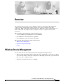
This section describes the wireless device role in common wireless network configurations. The access
point default configuration is as a root unit connected to a wired LAN or as the central unit in an
all-wireless network.
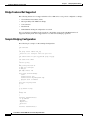
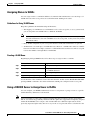
Root Unit on a Wired LAN
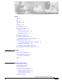
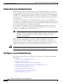
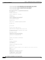
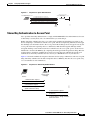
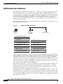
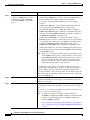
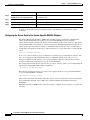
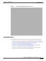
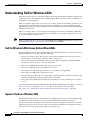
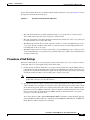
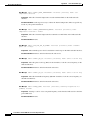
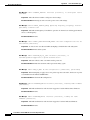
An access point connected directly to a wired LAN provides a connection point for wireless users.
Figure 1-1 shows access points acting as root units on a wired LAN.
Figure 1-1
Access Points as Root Units on a Wired LAN
Cisco Wireless Router and HWIC Configuration Guide
1-2
OL-6415-04
Chapter 1
Overview
Features
Features
This section lists features supported on access points running Cisco IOS software.
•
Access Point Link Role Flexibility—This feature allows the user to configure root and non-root
bridging mode functionality, universal client mode, and support of a WGB client device, in addition
to a root access point on the radio interface.
Note
Root/Non-Root bridging mode is supported only on modular ISR platforms, such as Cisco
3800 series , Cisco 2800 and Cisco 1841 series. Fixed ISR platforms, such as the Cisco 800
and Cisco 1800 do not support this feature.
•
QoS Basic Service Set (QBSS) support—This feature aligns Cisco QBSS implementation with the
evolving 802.11e standard. The QBSS element of the access point’s beacon advertises channel load
instead of traffic load. A new configuration command, dot11 phone dot11e has been added in
Release 12.4 that allows the standard QBSS Load element to be sent in the beacon. This command
should be used when compatible phones are employed in the network.
•
Secure Shell version 2 (SSHv2) support—SSH v2 is a standards-based protocol to provide secure
Telnet capability for router configuration and administration.
•
Support for Multiple BSSIDs—This feature permits a single access point to appear to the WLAN as
multiple virtual access points. It does this by assigning an access point with multiple Basic Service
Set IDs (MBSSIDs) or MAC addresses.
To determine whether a radio supports multiple basic SSIDs, enter the show controllers command
for the radio interface. The radio supports multiple basic SSIDs if the results include this line:
Number of supported simultaneous BSSID on radio_interface: 8
•
Support for Wi-Fi 802.11h and Dynamic Frequency Selection (DFS)—This feature allows access
points configured at the factory for use in Europe to detect radar signals such as military and weather
sources and switch channels on the access points.
•
SNMPv3—This feature enables SNMPv3 support on Cisco wireless devices to provide an additional
level of security.
•
World mode—Use this feature to communicate the access point’s regulatory setting information,
including maximum transmit power and available channels, to world mode-enabled clients. Clients
using world mode can be used in countries with different regulatory settings and automatically
conform to local regulations. World mode is supported only on the 2.4-GHz radio.
•
Multiple SSIDs—Create up to 16 SSIDs on the wireless device and assign any combination of these
settings to each SSID:
– Broadcast SSID mode for guests on your network
– Client authentication methods
– Maximum number of client associations
– VLAN identifier
– RADIUS accounting list identifier
– A separate SSID for infrastructure devices such as repeaters and workgroup bridges
Note
Only 10 SSIDs are supported on the Cisco 800 series platforms.
Cisco Wireless Router and HWIC Configuration Guide
OL-6415-04
1-3
Chapter 1
Overview
Features
•
VLANs—Assign VLANs to the SSIDs on the wireless device (one VLAN per SSID) to differentiate
policies and services among users.
•
QoS—Use this feature to support quality of service for prioritizing traffic from the Ethernet to the
access point. The access point also supports the voice-prioritization schemes used by 802.11b
wireless phones such as the Cisco 7920 and Spectralink's Netlink™.
•
RADIUS Accounting—Enable accounting on the access point to send accounting data about
wireless client devices to a RADIUS server on your network.
•
Enhanced security—Enable three advanced security features to protect against sophisticated attacks
on your wireless network's WEP keys: Message Integrity Check (MIC), WEP key hashing, and
broadcast WEP key rotation.
•
Enhanced authentication services—Set up repeater access points to authenticate to your network
like other wireless client devices. After you provide a network username and password for the
repeater, it authenticates to your network using Light Extensible Authentication Protocol (LEAP),
Cisco's wireless authentication method, and receives and uses dynamic WEP keys.
•
Wi-Fi Protected Access (WPA)—Wi-Fi Protected Access is a standards-based, interoperable
security enhancement that strongly increases the level of data protection and access control for
existing and future wireless LAN systems. It is derived from and will be forward-compatible with
the upcoming IEEE 802.11i standard. WPA leverages Temporal Key Integrity Protocol (TKIP) for
data protection and 802.1X for authenticated key management.
•
Access point as backup or stand-alone authentication server—You can configure an access point to
act as a local authentication server to provide authentication service for small wireless LANs
without a RADIUS server or to provide backup authentication service in case of a WAN link or a
server failure. The number of clients supported varies based on platform, with up to 1000 user
accounts supported on the higher end platforms.
•
Support for 802.11g radios—Cisco IOS Releases 12.4(2)T or later support the standard 802.11g,
2.4-GHz radio.
•
Support for Cisco 802.11a Radios—The 802.11a radios support all access point features introduced
in Cisco IOS Release 12.4 and later.
•
AES-CCMP—This feature supports Advanced Encryption Standard-Counter Mode with Cipher
Block Chaining Message Authentication Code Protocol (AES-CCMP). AES-CCMP is required for
Wi-Fi Protected Access 2 (WPA2) and IEEE 802.11i wireless LAN security.
•
IEEE 802.1X Local Authentication Service for EAP-FAST—This feature expands wireless domain
services (WDS) IEEE 802.1X local authentication to include support for Extensible Authentication
Protocol-Flexible Authentication via Secure Tunneling (EAP-FAST).
•
Wi-Fi Multimedia (WMM) Required Elements—This feature supports the required elements of
WMM. WMM is designed to improve the user experience for audio, video, and voice applications
over a Wi-Fi wireless connection. WMM is a subset of the IEEE 802.11e Quality of Service (QoS)
draft standard. WMM supports QoS prioritized media access via the Enhanced Distributed Channel
Access (EDCA) method. Optional elements of the WMM specification including call admission
control using traffic specifications (TSPEC) are not supported in this release.
•
VLAN Assignment By Name—This feature allows the RADIUS server to assign a client to a virtual
LAN (VLAN) identified by its VLAN name. In releases before Cisco IOS Release 12.4(5)T, the
RADIUS server identified the VLAN by ID. This feature is important for deployments where VLAN
IDs are not used consistently throughout the network.
Cisco Wireless Router and HWIC Configuration Guide
1-4
OL-6415-04
Chapter 1
Overview
•
Microsoft WPS IE SSIDL—This feature allows the access point to broadcast a list of configured
SSIDs (the SSIDL) in the Microsoft Wireless Provisioning Services Information Element (WPS IE).
A client with the ability to read the SSIDL can alert the user to the availability of the SSIDs. This
feature provides a bandwidth-efficient, software-upgradeable alternative to multiple broadcast
SSIDs (MB/SSIDs).
•
HTTP Web Server v1.1—This feature provides a consistent interface for users and applications by
implementing the HTTP 1.1 standard (see RFC 2616). In previous releases, Cisco software
supported only a partial implementation of HTTP 1.0. The integrated HTTP Server API supports
server application interfaces. When combined with the HTTPS and HTTP 1.1 Client features,
provides a complete, secure solution for HTTP services to and from Cisco devices.
Cisco Wireless Router and HWIC Configuration Guide
OL-6415-04
1-5
Chapter 1
Overview
Cisco Wireless Router and HWIC Configuration Guide
1-6
OL-6415-04
C H A P T E R
2
Configuring Radio Settings
This chapter describes how to configure radio settings for the wireless device. This chapter includes
these sections:
•
Enabling the Radio Interface, page 2-2
•
Roles in Radio Network, page 2-2
•
Configuring Network or Fallback Role, page 2-3
•
Sample Bridging Configuration, page 2-4
•
Universal Client Mode, page 2-7
•
Configuring Universal Client Mode, page 2-7
•
Configuring Radio Data Rates, page 2-10
•
Configuring Radio Transmit Power, page 2-12
•
Configuring Radio Channel Settings, page 2-14
•
Enabling and Disabling World Mode, page 2-20
•
Enabling and Disabling Short Radio Preambles, page 2-21
•
Configuring Transmit and Receive Antennas, page 2-22
•
Disabling and Enabling Access Point Extensions, page 2-23
•
Configuring the Ethernet Encapsulation Transformation Method, page 2-23
•
Enabling and Disabling Reliable Multicast to Workgroup Bridges, page 2-24
•
Enabling and Disabling Public Secure Packet Forwarding, page 2-25
•
Configuring Beacon Period and DTIM, page 2-26
•
Configuring RTS Threshold and Retries, page 2-27
•
Configuring Maximum Data Retries, page 2-27
•
Configuring Fragmentation Threshold, page 2-28
•
Enabling Short Slot Time for 802.11g Radios, page 2-28
•
Performing a Carrier Busy Test, page 2-29
Cisco Wireless ISR and HWIC Access Point Configuration Guide
OL-6415-04
2-1
Chapter 2
Configuring Radio Settings
Enabling the Radio Interface
Enabling the Radio Interface
The wireless device radios are disabled by default.
Note
In Cisco IOS Release 12.4 there is no default SSID. You must create a Radio Service Set Identifier
(SSID) before you can enable the radio interface.
Beginning in privileged EXEC mode, follow these steps to enable the wireless device radio:
Command
Purpose
Step 1
configure terminal
Enter global configuration mode.
Step 2
interface dot11radio { 0 | 1 }
Enter interface configuration mode for the radio interface. The
2.4-GHz radio is radio 0, and the 5-GHz radio is radio 1.
Step 3
ssid
Enter the SSID. The SSID can consist of up to 32 alphanumeric
characters. SSIDs are case sensitive.
Step 4
no shutdown
Enable the radio port.
Step 5
end
Return to privileged EXEC mode.
Step 6
copy running-config startup-config (Optional) Save your entries in the configuration file.
Use the shutdown command to disable the radio port.
Roles in Radio Network
You can configure the following roles in a radio network:
•
Network or Fallback Role
•
Universal Client Mode
Table 2-1 shows the role in the radio network for each device.
Table 2-1
Device Role in Radio Network Configuration
Role in Radio Network
Cisco 800 s Cisco 1800 Cisco 1841
eries ISRs series ISRs series
Cisco 2800 Cisco 3800
series ISRs series ISRs
Root access point
X
X
X
X
X
Root bridge with or without clients
–
–
X
X
X
Non-root bridge without clients
–
–
X
X
X
Universal client mode
X
X
X
X
X
Support of Workgroup bridge
clients
X
X
X
X
X
Cisco Wireless ISR and HWIC Access Point Configuration Guide
2-2
OL-6415-04
Chapter 2
Configuring Radio Settings
Configuring Network or Fallback Role
Configuring Network or Fallback Role
You can also configure a fallback role for root access points. The wireless device automatically assumes
the fallback role when its Ethernet port is disabled or disconnected from the wired LAN. Thefallback
role is Shutdown—the wireless device shuts down its radio and disassociates all client devices.
Beginning in privileged EXEC mode, follow these steps to set the wireless device’s radio network role
and fallback role:
Command
Purpose
Step 1
configure terminal
Enter global configuration mode.
Step 2
interface dot11radio { 0 | 1 }
Enter interface configuration mode for the radio interface. The
2.4-GHz radio is radio 0, and the 5-GHz radio is radio 1.
Step 3
station-role
Sets the wireless device role to universal client mode.
non-root {bridge | return}
root {fallback | repeater | wireless
clients | shutdown]}
•
Set the role to non-root bridge with or without wireless
clients, repeater access point, root access point or bridge,
scanner, or workgroup bridge.
•
The bridge mode radio supports point-to-point
configuration only.
•
The Ethernet port is shut down when any one of the radios
is configured as a repeater. Only one radio per access point
may be configured as a workgroup bridge or repeater.
•
The dot11radio 0|1 antenna-alignment command is
available when the access point is configured as a repeater.
•
Spanning Tree Protocol (STP) is configurable on Cisco
ISR series access points in bridge modes.
•
(Optional) Select the root access point’s fallback role. If
the wireless device’s Ethernet port is disabled or
disconnected from the wired LAN, the wireless device can
either shut down its radio port or become a repeater access
point associated to any nearby root access point.
Step 4
end
Step 5
copy running-config startup-config (Optional) Save your entries in the configuration file.
Return to privileged EXEC mode.
Cisco Wireless ISR and HWIC Access Point Configuration Guide
OL-6415-04
2-3
Chapter 2
Configuring Radio Settings
Configuring Network or Fallback Role
Bridge Features Not Supported
The following features are not supported when a Cisco ISR series access point is configured as a bridge:
•
Clear Channel Assessment (CCA)
•
Interoperability with 1400 series bridge
•
Concatenation
•
Install mode
•
EtherChannel and PageP configuration on switch
For root and non-root bridging mode operations, only bridge-group mode using BVI interface is
supported. Routing mode is not supported for root and non-root bridging operations.
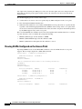
Sample Bridging Configuration
The following is a sample of a Root Bridge Configuration:
!
aaa new-model
!
!
aaa group server radius rad_eap
server 20.0.0.1 auth-port 1812 acct-port 1813
!
aaa authentication login eap_methods group rad_eap
!
aaa session-id common
!
resource policy
!
mmi polling-interval 60
no mmi auto-configure
no mmi pvc
mmi snmp-timeout 180
!
dot11 ssid airlink2-bridge
vlan 1
authentication open
authentication key-management wpa
wpa-psk ascii 0 12345678
!
dot11 priority-map avvid
ip cef
!
!
no ip domain lookup
!
!
bridge irb
!
!
interface FastEthernet0/0
no ip address
shutdown
duplex auto
speed auto
!
interface FastEthernet0/1
Cisco Wireless ISR and HWIC Access Point Configuration Guide
2-4
OL-6415-04
Chapter 2
Configuring Radio Settings
Configuring Network or Fallback Role
ip address 30.0.0.1 255.0.0.0
duplex auto
speed auto
!
interface Dot11Radio0/0/0
no ip address
!
encryption vlan 1 mode ciphers tkip
!
ssid airlink2-bridge
!
speed basic-1.0 basic-2.0 basic-5.5 6.0 9.0 basic-11.0 12.0 18.0 24.0 36.0 48.0 54.0
station-role root bridge
!
interface Dot11Radio0/0/0.1
encapsulation dot1Q 1 native
no snmp trap link-status
bridge-group 1
bridge-group 1 spanning-disabled
!
interface Dot11Radio0/0/1
no ip address
speed basic-6.0 9.0 basic-12.0 18.0 basic-24.0 36.0 48.0 54.0
station-role root
!
interface BVI1
ip address 20.0.0.1 255.0.0.0
!
ip route 0.0.0.0 0.0.0.0 20.0.0.5
!
!
ip http server
no ip http secure-server
!
!
radius-server local
nas 20.0.0.1 key 0 wireless
user non-root nthash 0 3741A4EE66E1AA56CD8B3A9038580DC9
!
radius-server host 20.0.0.1 auth-port 1812 acct-port 1813 key wireless
!
control-plane
!
bridge 1 route ip
!
!
line con 0
exec-timeout 0 0
line aux 0
line vty 0 4
!
!
webvpn context Default_context
ssl authenticate verify all
!
no inservice
!
end
The following is a sample of Non-Root Bridge Configuration:
no aaa new-model
Cisco Wireless ISR and HWIC Access Point Configuration Guide
OL-6415-04
2-5
Chapter 2
Configuring Radio Settings
Configuring Network or Fallback Role
!
resource policy
!
mmi polling-interval 60
no mmi auto-configure
no mmi pvc
mmi snmp-timeout 180
!
dot11 ssid airlink2-bridge
vlan 1
authentication open
authentication key-management wpa
wpa-psk ascii 0 12345678
!
dot11 priority-map avvid
ip cef
!
!
bridge irb
!
!
interface FastEthernet0/0
no ip address
duplex auto
speed auto
!
interface FastEthernet0/1
no ip address
duplex auto
speed auto
bridge-group 1
bridge-group 1 spanning-disabled
!
interface Dot11Radio0/1/0
no ip address
!
encryption vlan 1 mode ciphers tkip
!
ssid airlink2-bridge
!
speed basic-1.0 basic-2.0 basic-5.5 6.0 9.0 basic-11.0 12.0 18.0 24.0 36.0 48.0 54.0
station-role non-root bridge
!
interface Dot11Radio0/1/0.1
encapsulation dot1Q 1 native
no snmp trap link-status
bridge-group 1
bridge-group 1 spanning-disabled
!
interface BVI1
ip address 20.0.0.5 255.0.0.0
!
ip route 0.0.0.0 0.0.0.0 20.0.0.1
!
!
ip http server
no ip http secure-server
!
!
control-plane
!
bridge 1 route ip
!
!
Cisco Wireless ISR and HWIC Access Point Configuration Guide
2-6
OL-6415-04
Chapter 2
Configuring Radio Settings
Universal Client Mode
line con 0
exec-timeout 0 0
line aux 0
line vty 0 4
login
!
!
webvpn context Default_context
ssl authenticate verify all
!
no inservice
!
end
Universal Client Mode
Universal client mode is a wireless radio station role that allows the radio to act as a wireless client to
another access point or repeater. This feature is exclusive to the integrated radio running in the
Cisco 870, 1800, 2800, and 3800 Integrated Services Routers. It operates differently from the workgroup
bridge and non-root bridge modes that are supported on other Cisco wireless devices such as the
Cisco AP 1200.
Universal client mode has the following features and limitations:
•
You can configure universal client mode on the main dot11radio interface only, sub-interfaces are
not supported.
•
Universal client can associate to access points with radio VLANs.
•
Layer-3 routing is supported over the radio interface. However, there is no support for L2-bridging.
The user cannot configure a dot11radio interface with a bridge-group when in universal client mode.
•
SSIDs are required to be configured on the dot11 interface operating as a universal client;
association to an access point running in guest-mode is not supported.
•
The universal client can associate to Cisco access points, 3rd party access points, and repeaters. It
cannot associate to Cisco root bridges or Cisco workgroup bridges.
Configuring Universal Client Mode
You can configure universal client mode in Cisco ISR series by setting the radio interface station-role to
non-root. This is different from configuring the dot11radio interface to operate in non-root bridge mode,
which requires specifying the word bridge at the end of the command, ex: "station-role non-root
bridge".
Note
In other Cisco wireless products such as the Cisco AP1232, station-role non-root operates the same as
station-role non-root bridge. On the ISRs, the two commands are different: station-role non-root is
considered the universal client mode and station-role non-root bridge is considered the non-root bridge
mode.
Example using Cisco 2801 series router:
c2801#conf t
Enter configuration commands, one per line.
c2801(config)#interface Dot11Radio0/1/0
End with CNTL/Z.
Cisco Wireless ISR and HWIC Access Point Configuration Guide
OL-6415-04
2-7
Chapter 2
Configuring Radio Settings
Configuring Universal Client Mode
c2801(config-if)#station-role ?
non-root Non-root (bridge)
root
Root access point or bridge
c2801(config-if)#station-role non-root ?
bridge Bridge non-rootThis CLI enables non-root bridge mode.
<cr>
This CLI enables universal client mode
DHCP
IP DHCP addressing is supported in the Dot11Radio interface configured in universal client mode. The
following is an example of Dot11Radio configured with "ip address dhcp":
dot11 ssid test10
authentication open
!
interface Dot11Radio0/1/0
ip address dhcp
!
ssid test10
!
speed basic-1.0 basic-2.0 basic-5.5 6.0 9.0 basic-11.0 12.0 18.0 24.0 36.0 48.0 54.0
station-role non-root
Issuing a "show ip interface brief" will show the Virtual-Dot11Radio interface getting the IP address
from the DHCP server.
c2801_uc#sh ip int brief
Interface
FastEthernet0/0
FastEthernet0/1
Dot11Radio0/1/0
Dot11Radio0/1/1
Virtual-Dot11Radio0
c2801_uc#
IP-Address
unassigned
unassigned
unassigned
unassigned
200.1.1.2
OK?
YES
YES
YES
YES
YES
Method
NVRAM
NVRAM
DHCP
NVRAM
DHCP
Status
Protocol
administratively down down
administratively down down
up
up
administratively down down
up
up
NAT (Network Address Translation):
NAT translation takes place if you overload the interface which has an ip address. In the case of universal
client, the virtual-interface has the ip address obtained from the DHCP. Hence we require to overload the
virtual interface to aid NAT translation.
Note
NAT fails to translate with a DHCP address on the dot11 interface running in universal client mode.
The following configuration is supported on NAT:
ip nat inside source list 1 interface Virtual-Dot11Radio0 overload
The following is an example of a NAT configuration on a Cisco 1803 ISR:
C1803W_UC#
C1803W_UC#sh run
Building configuration...
Current
!
version
service
service
configuration : 2189 bytes
12.4
timestamps debug datetime msec
timestamps log datetime msec
Cisco Wireless ISR and HWIC Access Point Configuration Guide
2-8
OL-6415-04
Chapter 2
Configuring Radio Settings
Configuring Universal Client Mode
no service password-encryption
!
hostname C1803W_UC
!
boot-start-marker
boot-end-marker
!
logging buffered 4096 debugging
no logging console
!
no aaa new-model
!
resource policy
!
!
dot11 ssid hurricane
authentication open
authentication key-management wpa
wpa-psk ascii 0 allyouneedislove
!
dot11 ssid tsunami
authentication open
guest-mode
!
dot11 priority-map avvid
!
!
ip cef
no ip dhcp use vrf connected
ip dhcp excluded-address 100.1.1.1
!
ip dhcp pool jimmy
network 100.1.1.0 255.255.255.0
default-router 100.1.1.1
!
!
!
!
!
!
controller DSL 0
line-term cpe
!
!
bridge irb
!
interface Dot11Radio0
ip address 100.1.1.1 255.255.255.0
ip nat inside
ip virtual-reassembly
no ip route-cache cef
no ip route-cache
!
ssid tsunami
!
speed basic-1.0 basic-2.0 basic-5.5 6.0 9.0 basic-11.0 12.0 18.0 24.0 36.0 48.0 54.0
station-role root
rts threshold 2312
no cdp enable
!
interface Dot11Radio1
ip address dhcp
ip nat outside
ip virtual-reassembly
Cisco Wireless ISR and HWIC Access Point Configuration Guide
OL-6415-04
2-9
Chapter 2
Configuring Radio Settings
Configuring Radio Data Rates
!
encryption mode ciphers tkip
!
ssid hurricane
!
speed basic-6.0 9.0 basic-12.0 18.0 basic-24.0 36.0 48.0 54.0
station-role non-root
!
End
Configuring Radio Data Rates
You use the data rate settings to choose the data rates the wireless device uses for data transmission. The
rates are expressed in megabits per second. The wireless device always attempts to transmit at the highest
data rate set to Basic, also called Require on the browser-based interface. If there are obstacles or
interference, the wireless device steps down to the highest rate that allows data transmission. You can
set each data rate to one of three states:
Note
•
Basic (the GUI labels Basic rates as Required)—Allows transmission at this rate for all packets, both
unicast and multicast. At least one of the wireless device's data rates must be set to Basic.
•
Enabled—The wireless device transmits only unicast packets at this rate; multicast packets are sent
at one of the data rates set to Basic.
•
Disabled—The wireless device does not transmit data at this rate.
At least one data rate must be set to basic.
You can use the Data Rate settings to set an access point to serve client devices operating at specific data
rates. For example, to set the 2.4-GHz radio for 11 megabits per second (Mbps) service only, set the
11-Mbps rate to Basic and set the other data rates to Disabled. To set the wireless device to serve only
client devices operating at 1 and 2 Mbps, set 1 and 2 to Basic and set the rest of the data rates to
Disabled. To set the 2.4-GHz, 802.11g radio to serve only 802.11g client devices, set any Orthogonal
Frequency Division Multiplexing (OFDM) data rate (6, 9, 12, 18, 24, 36, 48, 54) to Basic. To set the
5-GHz radio for 54 Mbps service only, set the 54-Mbps rate to Basic and set the other data rates to
Disabled.
You can configure the wireless device to set the data rates automatically to optimize either the range or
the throughput. When you enter range for the data rate setting, the wireless device sets the 1 Mbps rate
to basic and the other rates to enabled. When you enter throughput for the data rate setting, the wireless
device sets all four data rates to basic.
Beginning in privileged EXEC mode, follow these steps to configure the radio data rates:
Command
Purpose
Step 1
configure terminal
Enter global configuration mode.
Step 2
interface dot11radio { 0 | 1 }
Enter interface configuration mode for the radio interface. The
2.4-GHz radio is radio 0, and the 5-GHz radio is radio 1.
Cisco Wireless ISR and HWIC Access Point Configuration Guide
2-10
OL-6415-04
Chapter 2
Configuring Radio Settings
Configuring Radio Data Rates
Step 3
Command
Purpose
speed
Set each data rate to basic or enabled, or enter range to
optimize range or throughput to optimize throughput.
These options are available for the
802.11b, 2.4-GHz radio:
•
{[1.0] [11.0] [2.0] [5.5] [basic-1.0]
[basic-11.0] [basic-2.0] [basic-5.5] |
range | throughput}
Enter 1.0, 2.0, 5.5, 6.0, 9.0, 11.0, 12.0, 18.0, 24.0, 36.0,
48.0, and 54.0 to set these data rates to enabled on the
802.11g, 2.4-GHz radio.
These options are available for the
802.11g, 2.4-GHz radio:
{[1.0] [2.0] [5.5] [6.0] [9.0] [11.0]
[12.0] [18.0] [24.0] [36.0] [48.0]
[54.0] [basic-1.0] [basic-2.0]
[basic-5.5] [basic-6.0] [basic-9.0]
[basic-11.0] [basic-12.0]
[basic-18.0] [basic-24.0]
[basic-36.0] [basic-48.0]
[basic-54.0] | range |
throughput [ofdm] | default }
These options are available for the
5-GHz radio:
(Optional) Enter 1.0, 2.0, 5.5, and 11.0 to set these data
rates to enabled on the 802.11b, 2.4-GHz radio.
Enter 6.0, 9.0, 12.0, 18.0, 24.0, 36.0, 48.0, and 54.0 to set
these data rates to enabled on the 5-GHz radio.
•
(Optional) Enter basic-1.0, basic-2.0, basic-5.5, and
basic-11.0 to set these data rates to basic on the 802.11b,
2.4-GHz radio.
Enter basic-1.0, basic-2.0, basic-5.5, basic-6.0, basic-9.0,
basic-11.0, basic-12.0, basic-18.0, basic-24.0, basic-36.0,
basic-48.0, and basic-54.0 to set these data rates to basic
on the 802.11g, 2.4-GHz radio.
Note
{[6.0] [9.0] [12.0] [18.0] [24.0]
[36.0] [48.0] [54.0] [basic-6.0]
[basic-9.0] [basic-12.0] [basic-18.0]
[basic-24.0] [basic-36.0]
[basic-48.0] [basic-54.0] |
range | throughput |default }
The client must support the basic rate that you select or
it cannot associate to the wireless device. If you select
12 Mbps or higher for the basic data rate on the 802.11g
radio, 802.11b client devices cannot associate to the
wireless device’s 802.11g radio.
Enter basic-6.0, basic-9.0, basic-12.0, basic-18.0,
basic-24.0, basic-36.0, basic-48.0, and basic-54.0 to set
these data rates to basic on the 5-GHz radio.
•
(Optional) Enter range or throughput to automatically
optimize radio range or throughput. When you enter
range, the wireless device sets the lowest data rate to basic
and the other rates to enabled. When you enter
throughput, the wireless device sets all data rates to basic.
(Optional) On the 802.11g radio, enter speed throughput
ofdm to set all OFDM rates (6, 9, 12, 18, 24, 36, and 48)
to basic (required) and set all the CCK rates (1, 2, 5.5, and
11) to disabled. This setting disables 802.11b protection
mechanisms and provides maximum throughput for
802.11g clients. However, it prevents 802.11b clients from
associating to the access point.
•
(Optional) Enter default to set the data rates to factory
default settings (not supported on 802.11b radios).
On the 802.11g radio, the default option sets rates 1, 2, 5.5,
and 11 to basic, and rates 6, 9, 12, 18, 24, 36, 48, and 54 to
enabled. These rate settings allow both 802.11b and
802.11g client devices to associate to the wireless device’s
802.11g radio.
On the 5-GHz radio, the default option sets rates 6.0, 12.0,
and 24.0 to basic, and rates 9.0, 18.0, 36.0, 48.0, and 54.0
to enabled.
Cisco Wireless ISR and HWIC Access Point Configuration Guide
OL-6415-04
2-11
Chapter 2
Configuring Radio Settings
Configuring Radio Transmit Power
Command
Purpose
Step 4
end
Return to privileged EXEC mode.
Step 5
copy running-config startup-config (Optional) Save your entries in the configuration file.
Use the no form of the speed command to remove one or more data rates from the configuration. This
example shows how to remove data rates basic-2.0 and basic-5.5 from the configuration:
router# configure terminal
router(config)# interface dot11radio 0
router(config-if)# no speed basic-2.0 basic-5.5
router(config-if)# end
Configuring Radio Transmit Power
Radio transmit power is based on the type of radio or radios installed in your access point and the
regulatory domain in which it operates. To determine what transmit power is available for your access
point and which regulatory domain it operates in, refer to the hardware installation guide for that device.
hardware installation guides are available at cisco.com. Follow these steps to view and download them:
Step 1
Browse to http://www.cisco.com.
Step 2
Click Technical Support & Documentation. A small window appears containing a list of technical
support links.
Step 3
Click Technical Support & Documentation. The Technical Support and Documentation page appears.
Step 4
In the Documentation & Tools section, choose Wireless. The Wireless Support Resources page appears.
Step 5
In the Wireless LAN Access section, choose the device you are working with. An introduction page for
the device appears.
Step 6
In the Install and Upgrade section, choose Install and Upgrade Guides. The Install and Upgrade Guides
page for the device appears.
Step 7
Choose the hardware installation guide for the device. The home page for the guide appears.
Step 8
In the left frame, click Channels and Antenna Settings.
Table 2-2 shows the relationship between mW and dBm.
Table 2-2
Translation between mW and dBm
dBm
-1
2
5
6
7
8
9
10
11
12
13
14
15
16
17
18
19
20
mW
1
2
3
4
5
6
8
10
12
15
20
25
30
40
50
60
80
100 125 150 200 250
21
22
23
24
Cisco Wireless ISR and HWIC Access Point Configuration Guide
2-12
OL-6415-04
Chapter 2
Configuring Radio Settings
Configuring Radio Transmit Power
Beginning in privileged EXEC mode, follow these steps to set the transmit power on access point radios:
Command
Purpose
Step 1
configure terminal
Enter global configuration mode.
Step 2
interface dot11radio { 0 | 1 }
Enter interface configuration mode for the radio interface. The
2.4-GHz radio is radio 0, and the 5-GHz radio is radio 1.
Step 3
power local
Set the transmit power for the 802.11g, 2.4-GHz radio to one of
the power levels allowed in your regulatory domain. All
settings are in mW.
power settings should be:
{3 | 4 | 5 | 6 | 7 | 10 | 13 | 15 | 17 | 18 |
On the 2.4-GHz, 802.11g radio, you can set Orthogonal
20 | maximum}
Frequency Division Multiplexing (OFDM) power levels and
Complementary Code Keying (CCK) power levels. CCK
modulation is supported by 802.11b and 802.11g devices.
OFDM modulation is supported by 802.11g and 802.11a
devices.
Note
See the hardware installation guide for your access
point to determine the power settings for your
regulatory domain.
Note
The 802.11g radio transmits at up to 100 mW for the 1,
2, 5.5, and 11Mbps data rates. However, for the 6, 9, 12,
18, 24, 36, 48, and 54Mbps data rates, the maximum
transmit power for the 802.11g radio is 30 mW.
Step 4
end
Step 5
copy running-config startup-config (Optional) Save your entries in the configuration file.
Return to privileged EXEC mode.
Use the no form of the power command to return the power setting to maximum, the default setting.
Limiting the Power Level for Associated Client Devices
You can also limit the power level on client devices that associate to the wireless device. When a client
device associates to the wireless device, the wireless device sends the maximum power level setting to
the client.
Note
Cisco AVVID documentation uses the term Dynamic Power Control (DTPC) to refer to limiting the
power level on associated client devices.
Beginning in privileged EXEC mode, follow these steps to specify a maximum allowed power setting on
all client devices that associate to the wireless device:
Command
Purpose
Step 1
configure terminal
Enter global configuration mode.
Step 2
interface dot11radio { 0 | 1 }
Enter interface configuration mode for the radio interface. The
2.4-GHz radio is radio 0, and the 5-GHz radio is radio 1.
Cisco Wireless ISR and HWIC Access Point Configuration Guide
OL-6415-04
2-13
Chapter 2
Configuring Radio Settings
Configuring Radio Channel Settings
Step 3
Command
Purpose
power client
Set the maximum power level allowed on client devices that
associate to the wireless device.
These options are available for
802.11b, 2.4-GHz clients (in mW):
Note
{ 1 | 5 | 20 | 30 | 50 | 100 | maximum}
The settings allowed in your regulatory domain might
differ from the settings listed here.
These options are available for
802.11g, 2.4-GHz clients (in mW):
{ 1 | 5 | 10 | 20 | 30 | 50 | 100 |
maximum}
These options are available for 5-GHz
clients (in mW):
{ 5 | 10 | 20 | 40 | maximum }
Step 4
end
Step 5
copy running-config startup-config (Optional) Save your entries in the configuration file.
Return to privileged EXEC mode.
Use the no form of the client power command to disable the maximum power level for associated clients.
Note
Access Point extensions must be enabled to limit the power level on associated client devices. Access
Point extensions are enabled by default.
Configuring Radio Channel Settings
The default channel setting for the wireless device radios is least congested; at startup, the wireless
device scans for and selects the least-congested channel. For the most consistent performance after a site
survey, however, we recommend that you assign a static channel setting for each access point. The
channel settings on the wireless device correspond to the frequencies available in your regulatory
domain. See the access point’s hardware installation guide for the frequencies allowed in your domain.
Each 2.4-GHz channel covers 22 MHz. The bandwidth for channels 1, 6, and 11 does not overlap, so you
can set up multiple access points in the same vicinity without causing interference. Both 802.11b and
802.11g 2.4-GHz radios use the same channels and frequencies.
The 5-GHz radio operates on eight channels from 5180 to 5320 MHz. Each channel covers 20 MHz, and
the bandwidth for the channels overlaps slightly. For best performance, use channels that are not adjacent
(44 and 46, for example) for radios that are close to each other.
Note
Too many access points in the same vicinity creates radio congestion that can reduce throughput. A
careful site survey can determine the best placement of access points for maximum radio coverage and
throughput.
Cisco Wireless ISR and HWIC Access Point Configuration Guide
2-14
OL-6415-04
Chapter 2
Configuring Radio Settings
Configuring Radio Channel Settings
Beginning in privileged EXEC mode, follow these steps to set the wireless device’s radio channel:
Command
Purpose
Step 1
configure terminal
Enter global configuration mode.
Step 2
interface dot11radio {0 | 1 }
Enter interface configuration mode for the radio interface. The
2.4-GHz radio is radio 0, and the 5-GHz radio is radio 1.
Step 3
channel
frequency | least-congested
Set the default channel for the wireless device radio. Table 2-3
through Table 2-6 show the available channels and frequencies for
all radios. To search for the least-congested channel on startup,
enter least-congested.
Note
The channel command is disabled for 5-GHz radios that
comply with European Union regulations on dynamic
frequency selection (DFS). See the “DFS Automatically
Enabled on Some 5-GHz Radio Channels” section on
page 2-19 for more information.
Step 4
end
Return to privileged EXEC mode.
Step 5
copy running-config
startup-config
(Optional) Save your entries in the configuration file.
Table 2-3 shows the available channels and frequencies for the IEEE 802.11b 2.4-GHz radio.
Table 2-3
Channels and Frequencies for 802.11b 2.4 GHz Radio
Regulatory Domains
Channel
Identifier
Center
Frequency (MHz)
Americas
(–A)
China
(–C)
EMEA
(–E)
Japan
(–J)
1
2412
X
X
X
X
2
2417
X
X
X
X
3
2422
X
X
X
X
4
2427
X
X
X
X
5
2432
X
X
X
X
6
2437
X
X
X
X
7
2442
X
X
X
X
8
2447
X
X
X
X
9
2452
X
X
X
X
10
2457
X
X
X
X
11
2462
X
X
X
X
12
2467
–
–
X
X
13
2472
–
–
X
X
14
2484
–
–
–
–
Cisco Wireless ISR and HWIC Access Point Configuration Guide
OL-6415-04
2-15
Chapter 2
Configuring Radio Settings
Configuring Radio Channel Settings
Table 2-4 shows the available frequencies for the 802.11g 2.4 GHz radio.
Table 2-4
Channels and Available Frequencies for 802.11g 2.4 GHz Radio
Regulatory Domains
Channel
Identifier
Center
Frequency
(MHz)
CCK
OFDM
CCK
OFDM
CCK
OFDM
1
2412
X
X
X
X
X
X
2
2417
X
X
X
X
X
X
3
2422
X
X
X
X
X
X
4
2427
X
X
X
X
X
X
5
2432
X
X
X
X
X
X
6
2437
X
X
X
X
X
X
7
2442
X
X
X
X
X
X
8
2447
X
X
X
X
X
X
9
2452
X
X
X
X
X
X
10
2457
X
X
X
X
X
X
11
2462
X
X
X
X
X
X
12
2467
–
–
X
X
X
X
13
2472
–
–
X
X
X
X
14
2484
–
–
–
–
X
–
Americas (–A)
EMEA (–E)
Japan (–J)
Table 2-5 shows the available channels and frequencies for the RM20A IEEE 802.11a radio
Table 2-5
Channels and Available Frequencies for the 802.11a Radio
Regulatory Domains
Channel
Identifier
Center
Frequency
(MHz)
CCK
OFDM
CCK
OFDM
CCK
OFDM
1
2412
X
X
X
X
X
X
2
2417
X
X
X
X
X
X
3
2422
X
X
X
X
X
X
4
2427
X
X
X
X
X
X
5
2432
X
X
X
X
X
X
6
2437
X
X
X
X
X
X
7
2442
X
X
X
X
X
X
8
2447
X
X
X
X
X
X
9
2452
X
X
X
X
X
X
10
2457
X
X
X
X
X
X
11
2462
X
X
X
X
X
X
12
2467
–
–
X
X
X
X
Americas (–A)
EMEA (–N)
Japan (–P)
Cisco Wireless ISR and HWIC Access Point Configuration Guide
2-16
OL-6415-04
Chapter 2
Configuring Radio Settings
Configuring Radio Channel Settings
Regulatory Domains
Channel
Identifier
Center
Frequency
(MHz)
CCK
OFDM
CCK
OFDM
CCK
OFDM
13
2472
–
–
X
X
X
X
14
2484
–
–
–
–
X
–
Americas (–A)
EMEA (–N)
Japan (–P)
Cisco Wireless ISR and HWIC Access Point Configuration Guide
OL-6415-04
2-17
Chapter 2
Configuring Radio Settings
Configuring Radio Channel Settings
Table 2-6 shows the available frequencies for the RM21A and RM22A IEEE 802.11a 5-GHz radios.
Table 2-6
Channel
ID
34
36
38
40
42
44
46
48
52
56
60
64
100
104
108
112
116
120
124
128
132
136
140
149
153
157
161
165
Channels and Available Frequencies for the 802.11a 5-GHz Radios
Center
Freq
(MHz)
5170
5180
5190
5200
5210
5220
5230
5240
5260
5280
5300
5320
5500
5520
5540
5560
5580
5600
5620
5640
5660
5680
5700
5745
5765
5785
5805
5825
Note
Americas
(–B)
China
(–C)
EMEA
(–E)
New
Zealand,
Australia
(–N)
Japan
(–P)
–
–
x
–
x
–
x
–
x
–
–
–
–
–
–
–
–
–
–
–
–
–
–
–
x
x
x
x
–
–
–
–
–
–
–
–
–
–
–
–
–
–
–
–
–
–
–
–
–
–
–
–
x
x
x
x
–
–
x
–
x
–
x
–
x
x
x
x
x
x
x
x
x
x
x
x
x
x
x
x
–
–
–
–
x
–
x
–
x
–
x
–
x
x
x
x
x
–
–
–
–
–
–
–
–
–
–
–
x
x
x
x
–
–
x
–
x
–
x
–
x
x
x
x
x
–
–
–
–
–
–
–
–
–
–
–
–
–
–
–
–
–
–
–
–
–
–
–
–
–
–
–
–
–
–
–
–
–
–
–
–
–
–
–
–
–
–
–
–
The frequencies allowed in your regulatory domain might differ from the frequencies listed here.
Cisco Wireless ISR and HWIC Access Point Configuration Guide
2-18
OL-6415-04
Chapter 2
Configuring Radio Settings
Configuring Radio Channel Settings
DFS Automatically Enabled on Some 5-GHz Radio Channels
Access points with 5-GHz radios configured at the factory for use in Europe now comply with
regulations that require radio devices to use Dynamic Frequency Selection (DFS) to detect radar signals
and avoid interfering with them. Radios configured for use in other regulatory domains do not use DFS.
When a DFS-enabled 5-GHz radio operates on one of the 15 channels listed in Table 2-7, the access point
automatically uses DFS to set the operating frequency.
Note
You cannot manually select a channel for DFS-enabled 5-GHz radios.
Table 2-7
DFS Automatically Enabled on these 5-GHz Channels
5-GHz Channels on Which DFS is Automatically Enabled
52 (5260 MHz)
104 (5520 MHz)
124 (5620 MHz)
56 (5280 MHz)
108 (5540 MHz)
128 (5640 MHz)
60 (5300 MHz)
112 (5560 MHz)
132 (5660 MHz)
64 (5320 MHz)
116 (5580 MHz)
136 (5680 MHz)
100 (5500 MHz)
120 (5600 MHz)
140 (5700 MHz)
When DFS is enabled, the access point monitors its operating frequency for radar signals. If it detects
radar signals on the channel, the access point takes these steps:
•
Blocks new transmissions on the channel.
•
Flushes the power-save client queues.
•
Broadcasts an 802.11h channel-switch announcement.
•
Disassociates remaining client devices.
•
Randomly selects a different 5-GHz channel.
•
If the channel selected is one of the channels in Table 2-7, scans the new channel for radar signals
for 60 seconds.
•
If there are no radar signals on the new channel, enables beacons and accepts client associations.
Note
The maximum legal transmit power is greater for some 5-GHz channels than for others. When it
randomly selects a 5-GHz channel on which power is restricted, the access point automatically reduces
transmit power to comply with power limits for that channel.
Note
We recommend that you use the world-mode dot11d country-code configuration interface command to
configure a country code on DFS-enabled radios. The IEEE 802.11h protocol requires access points to
include the country information element (IE) in beacons and probe responses. By default, however, the
country code in the IE is blank. You use the world-mode command to populate the country code IE.
Cisco Wireless ISR and HWIC Access Point Configuration Guide
OL-6415-04
2-19
Chapter 2
Configuring Radio Settings
Enabling and Disabling World Mode
Confirming that DFS is Enabled
Use the show controller dot11radio1 command to confirm that DFS is enabled. This example shows a
line from the output for the show controller command for a channel on which DFS is enabled:
Current Frequency: 5300 MHz
Channel 60 (DFS enabled)
Blocking Channels from DFS Selection
If your regulatory domain limits the channels that you can use in specific locations--for example, indoors
or outdoors--you can block groups of channels to prevent the access point from selecting them when DFS
is enabled. Use this configuration interface command to block groups of channels from DFS selection:
[no] dfs band [1] [2] [3] [4] block
The 1, 2, 3, and 4 options designate blocks of channels:
•
1—Specifies frequencies 5.150 to 5.250 GHz. This group of frequencies is also known as the UNII-1
band.
•
2—Specifies frequencies 5.250 to 5.350 GHz. This group of frequencies is also known as the UNII-2
band.
•
3—Specifies frequencies 5.470 to 5.725 GHz.
•
4—Specifies frequencies 5.725 to 5.825 GHz. This group of frequencies is also known as the UNII-3
band.
This example shows how to prevent the access point from selecting frequencies 5.150 to 5.350 GHz
during DFS:
router(config-if)# dfs band 1 2 block
This example shows how to unblock frequencies 5.150 to 5.350 for DFS:
router(config-if)# no dfs band 1 2 block
This example shows how to unblock all frequencies for DFS:
router(config-if)# no dfs band block
Enabling and Disabling World Mode
You can configure the wireless device to support 802.11d world mode or Cisco legacy world mode.
When you enable world mode, the wireless device adds channel carrier set information to its beacon.
Client devices with world mode enabled receive the carrier set information and adjust their settings
automatically. For example, a client device used primarily in Japan could rely on world mode to adjust
its channel and power settings automatically when it travels to Italy and joins a network there. Cisco
client devices running firmware version 5.30.17 or later detect whether the wireless device is using
802.11d or Cisco legacy world mode and automatically use world mode that matches the mode used by
the wireless device. World mode is disabled by default.
Cisco Wireless ISR and HWIC Access Point Configuration Guide
2-20
OL-6415-04
Chapter 2
Configuring Radio Settings
Enabling and Disabling Short Radio Preambles
Beginning in privileged EXEC mode, follow these steps to enable world mode:
Command
Purpose
Step 1
configure terminal
Enter global configuration mode.
Step 2
interface dot11radio { 0 | 1}
Enter interface configuration mode for the radio interface.
Step 3
world-mode
dot11d country_code code
{ both | indoor | outdoor }
| legacy
Enable world mode.
•
Enter the dot11d option to enable 802.11d world mode.
– When you enter the dot11d option, you must enter a
two-character ISO country code (for example, the ISO
country code for the United States is US). You can find
a list of ISO country codes at the ISO website.
– After the country code, you must enter indoor,
outdoor, or both to indicate the placement of the
wireless device.
•
Note
Enter the legacy option to enable Cisco legacy world
mode.
Access Point extensions must be enabled for legacy
world mode operation, but Access Point extensions are
not required for 802.11d world mode. Access Point
extensions are enabled by default.
Step 4
end
Step 5
copy running-config startup-config (Optional) Save your entries in the configuration file.
Return to privileged EXEC mode.
Use the no form of the command to disable world mode.
Enabling and Disabling Short Radio Preambles
The radio preamble (sometimes called a header) is a section of data at the head of a packet that contains
information that the wireless device and client devices need when sending and receiving packets. You
can set the radio preamble to long or short:
•
Short—A short preamble improves throughput performance. Cisco Access Point Wireless LAN
Client Adapters support short preambles.
•
Long—A long preamble ensures compatibility between the wireless device and all early models of
Cisco Access Point Wireless LAN Adapters (PC4800 and PC4800A). If these client devices do not
associate to the wireless devices, you should use short preambles.
You cannot configure short or long radio preambles on the 5-GHz radio.
Beginning in privileged EXEC mode, follow these steps to disable short radio preambles:
Command
Purpose
Step 1
configure terminal
Enter global configuration mode.
Step 2
interface dot11radio { 0 }
Enter interface configuration mode for the 2.4-GHz radio
interface.
Cisco Wireless ISR and HWIC Access Point Configuration Guide
OL-6415-04
2-21
Chapter 2
Configuring Radio Settings
Configuring Transmit and Receive Antennas
Command
Purpose
Step 3
no preamble-short
Disable short preambles and enable long preambles.
Step 4
end
Return to privileged EXEC mode.
Step 5
copy running-config startup-config (Optional) Save your entries in the configuration file.
Short preambles are enabled by default. Use the preamble-short command to enable short preambles if
they are disabled.
Configuring Transmit and Receive Antennas
You can select the antenna the wireless device uses to receive and transmit data. There are three options
for both the receive and the transmit antenna:
•
Diversity—This default setting tells the wireless device to use the antenna that receives the best
signal. If the wireless device has two fixed (non-removable) antennas, you should use this setting
for both receive and transmit.
•
Right—If the wireless device has removable antennas and you install a high-gain antenna on the
wireless device's right connector, you should use this setting for both receive and transmit. When
you look at the wireless device's back panel, the right antenna is on the right.
•
Left—If the wireless device has removable antennas and you install a high-gain antenna on the
wireless device's left connector, you should use this setting for both receive and transmit. When you
look at the wireless device's back panel, the left antenna is on the left.
Beginning in privileged EXEC mode, follow these steps to select the antennas the wireless device uses
to receive and transmit data:
Command
Purpose
Step 1
configure terminal
Enter global configuration mode.
Step 2
interface dot11radio { 0 | 1 }
Enter interface configuration mode for the radio interface. The
2.4-GHz radio is radio 0, and the 5-GHz radio is radio 1.
Step 3
antenna receive
{diversity | left | right}
Set the receive antenna to diversity, left, or right.
Step 4
Note
For best performance, leave the receive antenna setting
at the default setting, diversity.
Note
The Cisco 850 series routers do not support diversity.
antenna transmit
{diversity | left | right}
Set the transmit antenna to diversity, left, or right.
Step 5
end
Return to privileged EXEC mode.
Step 6
copy running-config startup-config (Optional) Save your entries in the configuration file.
Note
For best performance, leave the transmit antenna
setting at the default setting, diversity.
Cisco Wireless ISR and HWIC Access Point Configuration Guide
2-22
OL-6415-04
Chapter 2
Configuring Radio Settings
Disabling and Enabling Access Point Extensions
Disabling and Enabling Access Point Extensions
By default, the wireless device uses Cisco Access Point extensions to detect the capabilities of
Cisco Access Point client devices and to support features that require specific interaction between the
wireless device and associated client devices. Cisco Access Point extensions must be enabled to support
these features:
•
Load balancing—The wireless device uses Access Point extensions to direct client devices to an
access point that provides the best connection to the network based on factors such as number of
users, bit error rates, and signal strength.
•
Message Integrity Check (MIC)—MIC is an additional WEP security feature that prevents attacks
on encrypted packets called bit-flip attacks. The MIC, implemented on both the wireless device and
all associated client devices, adds a few bytes to each packet to make the packets tamper-proof.
•
World mode (legacy only)—Client devices with legacy world mode enabled receive carrier set
information from the wireless device and adjust their settings automatically. Access Point
extensions are not required for 802.11d world mode operation.
•
Limiting the power level on associated client devices—When a client device associates to the
wireless device, the wireless device sends the maximum allowed power level setting to the client.
Disabling Access Point extensions disables the features listed above, but it sometimes improves the
ability of other companies devices to associate to the wireless device.
Access Point extensions are enabled by default. Beginning in privileged EXEC mode, follow these steps
to disable Access Point extensions:
Command
Purpose
Step 1
configure terminal
Enter global configuration mode.
Step 2
interface dot11radio { 0 | 1 }
Enter interface configuration mode for the radio interface. The
2.4-GHz radio is radio 0, and the 5-GHz radio is radio 1.
Step 3
no dot11 extension aironet
Disable Access Point extensions.
Step 4
end
Return to privileged EXEC mode.
Step 5
copy running-config startup-config (Optional) Save your entries in the configuration file.
Use the dot11 extension aironet command to enable Access Point extensions if they are disabled.
Configuring the Ethernet Encapsulation Transformation Method
When the wireless device receives data packets that are not 802.3 packets, the wireless device must
format the packets to 802.3 using an encapsulation transformation method. These are the two
transformation methods:
•
802.1H—This method provides optimum performance for Cisco Access Point wireless products.
This is the default setting.
•
snap—Use this setting to ensure interoperability with non-Cisco Access Point wireless equipment.
RFC1042 does not provide the interoperability advantages of 802.1H but is used by other
manufacturers of wireless equipment. This is the default setting.
Cisco Wireless ISR and HWIC Access Point Configuration Guide
OL-6415-04
2-23
Chapter 2
Configuring Radio Settings
Enabling and Disabling Reliable Multicast to Workgroup Bridges
Beginning in privileged EXEC mode, follow these steps to configure the encapsulation transformation
method:
Command
Purpose
Step 1
configure terminal
Enter global configuration mode.
Step 2
interface dot11radio { 0 | 1 }
Enter interface configuration mode for the radio interface. The
2.4-GHz radio is radio 0, and the 5-GHz radio is radio 1.
Step 3
payload-encapsulation
snap | dot1h
Set the encapsulation transformation method to RFC1042
(snap) or 802.1h (dot1h, the default setting).
Step 4
end
Return to privileged EXEC mode.
Step 5
copy running-config startup-config (Optional) Save your entries in the configuration file.
Enabling and Disabling Reliable Multicast to Workgroup
Bridges
The Reliable multicast messages from the access point to workgroup bridges setting limits reliable
delivery of multicast messages to approximately 20 Cisco Access Point Workgroup Bridges that are
associated to the wireless device. The default setting, disabled, reduces the reliability of multicast
delivery to allow more workgroup bridges to associate to the wireless device.
Access points and bridges normally treat workgroup bridges not as client devices but as infrastructure
devices, like access points or bridges. Treating a workgroup bridge as an infrastructure device means that
the wireless device reliably delivers multicast packets, including Address Resolution Protocol (ARP)
packets, to the workgroup bridge.
The performance cost of reliable multicast delivery—duplication of each multicast packet sent to each
workgroup bridge—limits the number of infrastructure devices, including workgroup bridges, that can
associate to the wireless device. To increase beyond 20 the number of workgroup bridges that can
maintain a radio link to the wireless device, the wireless device must reduce the delivery reliability of
multicast packets to workgroup bridges. With reduced reliability, the wireless device cannot confirm
whether multicast packets reach the intended workgroup bridge, so workgroup bridges at the edge of the
wireless device's coverage area might lose IP connectivity. When you treat workgroup bridges as client
devices, you increase performance but reduce reliability.
Note
This feature is best suited for use with stationary workgroup bridges. Mobile workgroup bridges might
encounter spots in the wireless device's coverage area where they do not receive multicast packets and
lose communication with the wireless device even though they are still associated to it.
A Cisco Access Point Workgroup Bridge provides a wireless LAN connection for up to eight
Ethernet-enabled devices.
This feature is not supported on the 5-GHz radio.
Cisco Wireless ISR and HWIC Access Point Configuration Guide
2-24
OL-6415-04
Chapter 2
Configuring Radio Settings
Enabling and Disabling Public Secure Packet Forwarding
Beginning in privileged EXEC mode, follow these steps to configure the encapsulation transformation
method:
Command
Purpose
Step 1
configure terminal
Enter global configuration mode.
Step 2
interface dot11radio { 0 }
Enter interface configuration mode for the 2.4-GHz radio
interface.
Step 3
infrastructure-client
Enable reliable multicast messages to workgroup bridges.
Step 4
end
Return to privileged EXEC mode.
Step 5
copy running-config startup-config (Optional) Save your entries in the configuration file.
Use the no form of the command to disable reliable multicast messages to workgroup bridges.
Enabling and Disabling Public Secure Packet Forwarding
Public Secure Packet Forwarding (PSPF) prevents client devices associated to an access point from
inadvertently sharing files or communicating with other client devices associated to the access point. It
provides Internet access to client devices without providing other capabilities of a LAN. This feature is
useful for public wireless networks like those installed in airports or on college campuses.
Note
To prevent communication between clients associated to different access points, you must set up
protected ports on the switch to which the wireless devices are connected. See the “Configuring
Protected Ports” section on page 2-26 for instructions on setting up protected ports.
To enable and disable PSPF using CLI commands on the wireless device, you use bridge groups. You
can find a detailed explanation of bridge groups and instructions for implementing them in this
document:
•
Cisco IOS Bridging and IBM Networking Configuration Guide, Release 12.2. Click this link to
browse to the Configuring Transparent Bridging chapter:
http://www.cisco.com/univercd/cc/td/doc/product/software/ios122/122cgcr/fibm_c/bcfpart1/bcftb.
htm
You can also enable and disable PSPF using the web-browser interface. The PSPF setting is on the Radio
Settings pages.
PSPF is disabled by default. Beginning in privileged EXEC mode, follow these steps to enable PSPF:
Command
Purpose
Step 1
configure terminal
Enter global configuration mode.
Step 2
interface dot11radio { 0 | 1 }
Enter interface configuration mode for the radio interface. The
2.4-GHz radio is radio 0, and the 5-GHz radio is radio 1.
Step 3
bridge-group group port-protected
Enable PSPF.
Step 4
end
Return to privileged EXEC mode.
Step 5
copy running-config startup-config (Optional) Save your entries in the configuration file.
Cisco Wireless ISR and HWIC Access Point Configuration Guide
OL-6415-04
2-25
Chapter 2
Configuring Radio Settings
Configuring Beacon Period and DTIM
Use the no form of the command to disable PSPF.
Configuring Protected Ports
To prevent communication between client devices associated to different access points on your wireless
LAN, you must set up protected ports on the switch to which the wireless devices are connected.
Beginning in privileged EXEC mode, follow these steps to define a port on your switch as a protected
port:
Command
Purpose
Step 1
configure terminal
Enter global configuration mode.
Step 2
interface interface-id
Enter interface configuration mode, and enter the type and
number of the switchport interface to configure, such as
gigabitethernet0/1.
Step 3
switchport protected
Configure the interface to be a protected port.
Step 4
end
Return to privileged EXEC mode.
Step 5
show interfaces interface-id
switchport
Verify your entries.
Step 6
copy running-config startup-config (Optional) Save your entries in the configuration file.
To disable protected port, use the no switchport protected interface configuration command.
For detailed information on protected ports and port blocking, see the “Configuring Port-Based Traffic
Control” chapter in the Catalyst 3550 Multilayer Switch Software Configuration Guide, 12.1(12c)EA1
at:
http://www.cisco.com/en/US/products/hw/switches/ps646/products_configuration_guide_book09186a
008011591c.html
Configuring Beacon Period and DTIM
The beacon period is the amount of time between access point beacons in kilo-microseconds. One
kilo-microseconds equals 1,024 microseconds. The Data Beacon Rate, always a multiple of the beacon
period, determines how often the beacon contains a delivery traffic indication message (DTIM). The
DTIM tells power-save client devices that a packet is waiting for them.
For example, if the beacon period is set at 100, its default setting, and the data beacon rate is set at 2, its
default setting, then the wireless device sends a beacon containing a DTIM every 200 kilo-microseconds.
One kilo-microsecond equals 1,024 microseconds.
The default beacon period is 100, and the default DTIM is 2. Beginning in privileged EXEC mode,
follow these steps to configure the beacon period and the DTIM:
Command
Purpose
Step 1
configure terminal
Enter global configuration mode.
Step 2
interface dot11radio { 0 | 1 }
Enter interface configuration mode for the radio interface. The
2.4-GHz radio is radio 0, and the 5-GHz radio is radio 1.
Cisco Wireless ISR and HWIC Access Point Configuration Guide
2-26
OL-6415-04
Chapter 2
Configuring Radio Settings
Configuring RTS Threshold and Retries
Command
Purpose
Step 3
beacon period value
Set the beacon period. Enter a value in Kilomicroseconds.
Step 4
beacon dtim-period value
Set the DTIM. Enter a value in Kilomicroseconds.
Step 5
end
Return to privileged EXEC mode.
Step 6
copy running-config startup-config (Optional) Save your entries in the configuration file.
Configuring RTS Threshold and Retries
The RTS threshold determines the packet size at which the wireless device issues a request to send (RTS)
before sending the packet. A low RTS Threshold setting can be useful in areas where many client devices
are associating with the wireless device, or in areas where the clients are far apart and can detect only
the wireless device and not each other. You can enter a setting ranging from 0 to 2347 bytes.
Maximum RTS retries is the maximum number of times the wireless device issues an RTS before
stopping the attempt to send the packet over the radio. Enter a value from 1 to 128.
The default RTS threshold is 2312, and the default maximum RTS retries setting is 32. Beginning in
privileged EXEC mode, follow these steps to configure the RTS threshold and maximum RTS retries:
Command
Purpose
Step 1
configure terminal
Enter global configuration mode.
Step 2
interface dot11radio { 0 | 1 }
Enter interface configuration mode for the radio interface. The
2.4-GHz radio is radio 0, and the 5-GHz radio is radio 1.
Step 3
rts threshold value
Set the RTS threshold. Enter an RTS threshold from 0 to 2347.
Step 4
rts retries value
Set the maximum RTS retries. Enter a setting from 1 to 128.
Step 5
end
Return to privileged EXEC mode.
Step 6
copy running-config startup-config (Optional) Save your entries in the configuration file.
Use the no form of the command to reset the RTS settings to defaults.
Configuring Maximum Data Retries
The maximum data retries setting determines the number of attempts the wireless device makes to send
a packet before giving up and dropping the packet.
The default setting is 32. Beginning in privileged EXEC mode, follow these steps to configure the
maximum data retries:
Command
Purpose
Step 1
configure terminal
Enter global configuration mode.
Step 2
interface dot11radio { 0 | 1 }
Enter interface configuration mode for the radio interface. The
2.4-GHz radio is radio 0, and the 5-GHz radio is radio 1.
Step 3
packet retries value
Set the maximum data retries. Enter a setting from 1 to 128.
Cisco Wireless ISR and HWIC Access Point Configuration Guide
OL-6415-04
2-27
Chapter 2
Configuring Radio Settings
Configuring Fragmentation Threshold
Command
Purpose
Step 4
end
Return to privileged EXEC mode.
Step 5
copy running-config startup-config (Optional) Save your entries in the configuration file.
Use the no form of the command to reset the setting to defaults.
Configuring Fragmentation Threshold
The fragmentation threshold determines the size at which packets are fragmented (sent as several pieces
instead of as one block). Use a low setting in areas where communication is poor or where there is a great
deal of radio interference.
The default setting is 2338 bytes. Beginning in privileged EXEC mode, follow these steps to configure
the fragmentation threshold:
Command
Purpose
Step 1
configure terminal
Enter global configuration mode.
Step 2
interface dot11radio { 0 | 1 }
Enter interface configuration mode for the radio interface. The
2.4-GHz radio is radio 0, and the 5-GHz radio is radio 1.
Step 3
fragment-threshold value
Set the fragmentation threshold. Enter a setting from 256 to
2346 bytes for the 2.4-GHz radio. Enter a setting from 256 to
2346 bytes for the 5-GHz radio.
Step 4
end
Return to privileged EXEC mode.
Step 5
copy running-config startup-config (Optional) Save your entries in the configuration file.
Use the no form of the command to reset the setting to defaults.
Enabling Short Slot Time for 802.11g Radios
You can increase throughput on the 802.11g, 2.4-GHz radio by enabling short slot time. Reducing the
slot time from the standard 20 microseconds to the 9-microsecond short slot time decreases the overall
backoff, which increases throughput. Backoff, which is a multiple of the slot time, is the random length
of time that a station waits before sending a packet on the LAN.
Many 802.11g radios support short slot time, but some do not. When you enable short slot time, the
wireless device uses the short slot time only when all clients associated to the 802.11g, 2.4-GHz radio
support short slot time.
Short slot time is supported only on the 802.11g, 2.4-GHz radio. Short slot time is disabled by default.
Command
Purpose
Step 1
router(config-if)# slot-time-short
In radio interface mode, enter this command to enable short slot
time.
Step 2
no slot-time-short
(optional) Enter no slot-time-short to disable short slot time.
Cisco Wireless ISR and HWIC Access Point Configuration Guide
2-28
OL-6415-04
Chapter 2
Configuring Radio Settings
Performing a Carrier Busy Test
Performing a Carrier Busy Test
You can perform a carrier busy test to check the radio activity on wireless channels. During the carrier
busy test, the wireless device drops all associations with wireless networking devices for 4 seconds while
it conducts the carrier test and then displays the test results.
In privileged EXEC mode, enter this command to perform a carrier busy test:
dot11 interface-number carrier busy
For interface-number, enter dot11radio 0 to run the test on the 2.4-GHz radio, or enter dot11radio 1 to
run the test on the 5-GHz radio.
Use the show dot11 carrier busy command to re-display the carrier busy test results.
Cisco Wireless ISR and HWIC Access Point Configuration Guide
OL-6415-04
2-29
Chapter 2
Configuring Radio Settings
Performing a Carrier Busy Test
Cisco Wireless ISR and HWIC Access Point Configuration Guide
2-30
OL-6415-04
C H A P T E R
3
Configuring Multiple SSIDs
This chapter describes how to configure and manage multiple service set identifiers (SSIDs) on the
access point. This chapter contains the following sections:
•
Understanding Multiple SSIDs, page 3-2
•
Configuring Multiple SSIDs, page 3-3
•
Configuring Multiple Basic SSIDs, page 3-6
•
Enabling MBSSID and SSIDL at the same time, page 3-7
Cisco Wireless ISR and HWIC Access Point Configuration Guide
OL-6415-04
3-1
Chapter 3
Configuring Multiple SSIDs
Understanding Multiple SSIDs
Understanding Multiple SSIDs
The SSID is a unique identifier that wireless networking devices use to establish and maintain wireless
connectivity. Multiple access points on a network or subnetwork can use the same SSIDs. SSIDs are case
sensitive and can contain up to 32 alphanumeric characters. Do not include spaces in your SSIDs.
You can configure up to 16 SSIDs on your HWIC-APs and assign different configuration settings to each
SSID. All the SSIDs are active at the same time; that is, client devices can associate to the access point
using any of the SSIDs. These are the settings you can assign to each SSID:
•
VLAN
•
Client authentication method
Note
For detailed information on client authentication types, see Chapter 6, “Configuring
Authentication Types.”
•
Maximum number of client associations using the SSID
•
RADIUS accounting for traffic using the SSID
•
Guest mode
•
Repeater mode, including authentication username and password
•
Redirection of packets received from client devices
If you want the access point to allow associations from client devices that do not specify an SSID in their
configurations, you can set up a guest SSID. The access point includes the guest SSID in its beacon.
If your access point will be a repeater or will be a root access point that acts as a parent for a repeater,
you can set up an SSID for use in repeater mode. You can assign an authentication username and
password to the repeater-mode SSID to allow the repeater to authenticate to your network like a client
device.
If your network uses VLANs, you can assign one SSID to a VLAN, and client devices using the SSID
are grouped in that VLAN.
SSID Configuration Methods Supported by Cisco IOS Releases
Cisco introduced global-mode SSID configuration in a prior Cisco IOS Release to simplify configuration
of SSID parameters under multiple interfaces. Configuration of SSID parameters at the interface level
was supported in some Cisco IOS releases for backward compatibility, but configuration of SSID
parameters at the interface level will be totally disabled in releases after Cisco IOS Release 12.4(15)T.
Cisco IOS Release 12.4(15)T supports configuration of SSID parameters at the interface level on the
CLI, but the SSIDs are stored in global mode. Storing all SSIDs in global mode ensures that the SSID
configuration remains correct when you upgrade to release later than Cisco IOS Release 12.4(15)T.
If you need to upgrade to a release later than 12.4(15)T, you should first upgrade to Cisco IOS Release
12.4(15)T, save the configuration file, upgrade to the target release, and load the saved configuration file.
This process ensures that your interface-level SSID configuration correctly translates to global mode.
If you upgrade directly from 12.4(15)T release or earlier to a 12.4(15)T or later release, your
interface-level SSID configuration is deleted.
Cisco Wireless ISR and HWIC Access Point Configuration Guide
3-2
OL-6415-04
Chapter 3
Configuring Multiple SSIDs
Configuring Multiple SSIDs
Configuring Multiple SSIDs
This section contains configuration information for multiple SSIDs:
Note
•
Creating an SSID Globally, page 3-3
•
Using a RADIUS Server to Restrict SSIDs, page 3-5
In Cisco IOS Release 12.4(15)T and later, you configure SSIDs globally and then apply them to a
specific radio interface. Follow the instructions in the “Creating an SSID Globally” section on page 3-3
to configure SSIDs globally.
Creating an SSID Globally
In Cisco IOS Releases 12.4 and later, you can configure SSIDs globally or for a specific radio interface.
When you use the dot11 ssid global configuration command to create an SSID, you can use the ssid
configuration interface command to assign the SSID to a specific interface.
When an SSID has been created in global configuration mode, the ssid configuration interface command
attaches the SSID to the interface but does not enter ssid configuration mode. However, if the SSID has
not been created in global configuration mode, the ssid command puts the CLI into SSID configuration
mode for the new SSID.
Note
SSIDs created in Cisco IOS Releases 12.3(7)JA and later become invalid if you downgrade the software
version to an earlier release.
Beginning in privileged EXEC mode, follow these steps to create an SSID globally. After you create an
SSID, you can assign it to specific radio interfaces.
Command
Purpose
Step 1
configure terminal
Enter global configuration mode.
Step 2
dot11 ssid ssid-string
Create an SSID and enter SSID configuration mode for the new
SSID. The SSID can consist of up to 32 alphanumeric
characters. SSIDs are case sensitive.
Note
+, ., ], ?, $, TAB, and trailing spaces are invalid
characters for SSIDs.
Step 3
authentication client
username username
password password
(Optional) Set an authentication username and password that
the access point uses to authenticate to the network when in
repeater mode. Set the username and password on the SSID that
the repeater access point uses to associate to a root access point,
or with another repeater.
Step 4
accounting list-name
(Optional) Enable RADIUS accounting for this SSID. For
list-name, specify the accounting method list. Click this link
for more information on method lists:
http://www.cisco.com/univercd/cc/td/doc/product/software/ios
122/122cgcr/fsecur_c/fsaaa/scfacct.htm#xtocid2
Cisco Wireless ISR and HWIC Access Point Configuration Guide
OL-6415-04
3-3
Chapter 3
Configuring Multiple SSIDs
Configuring Multiple SSIDs
Command
Purpose
Step 5
vlan vlan-id
(Optional) Assign the SSID to a VLAN on your network. Client
devices that associate using the SSID are grouped into this
VLAN. You can assign only one SSID to a VLAN.
Step 6
guest-mode
(Optional) Designate the SSID as your access point’s
guest-mode SSID. The access point includes the SSID in its
beacon and allows associations from client devices that do not
specify an SSID.
Step 7
infrastructure-ssid [optional]
(Optional) Designate the SSID as the SSID that other access
points and workgroup bridges use to associate to this access
point. If you do not designate an SSID as the infrastructure
SSID, infrastructure devices can associate to the access point
using any SSID. If you designate an SSID as the infrastructure
SSID, infrastructure devices must associate to the access point
using that SSID unless you also enter the optional keyword.
Step 8
interface dot11radio { 0 | 1 }
Enter interface configuration mode for the radio interface to
which you want to assign the SSID. The 2.4-GHz radio is radio
0, and the 5-GHz radio is radio 1.
Step 9
ssid ssid-string
Assign the global SSID that you created in Step 2 to the radio
interface.
Step 10
end
Return to privileged EXEC mode.
Step 11
copy running-config startup-config (Optional) Save your entries in the configuration file.
Note
You use the ssid command’s authentication options to configure an authentication type for each SSID.
See Chapter 6, “Configuring Authentication Types,” for instructions on configuring authentication
types.
Use the no form of the command to disable the SSID or to disable SSID features.
This example shows how to:
•
Name an SSID
•
Configure the SSID for RADIUS accounting
•
Set the maximum number of client devices that can associate using this SSID to 15
•
Assign the SSID to a VLAN
•
Assign the SSID to a radio interface
router# configure terminal
router(config)# dot11 ssid batman
router(config-ssid)# accounting accounting-method-list
router(config-ssid)# max-associations 15
router(config-ssid)# vlan 3762
router(config-ssid)# exit
router(config)# interface dot11radio 0
router(config-if)# ssid batman
Cisco Wireless ISR and HWIC Access Point Configuration Guide
3-4
OL-6415-04
Chapter 3
Configuring Multiple SSIDs
Configuring Multiple SSIDs
Viewing SSIDs Configured Globally
Use this command to view configuration details for SSIDs that are configured globally:
router# show running-config ssid ssid-string
Using Spaces in SSIDs
In Cisco IOS Release 12.4(15)T, you can include spaces in an SSID, but trailing spaces (spaces at the
end of an SSID) are invalid. However, any SSIDs created in previous versions having trailing spaces are
recognized. Trailing spaces make it appear that you have identical SSIDs configured on the same access
point. If you think identical SSIDs are on the access point, use the show dot11 associations privileged
EXEC command to check any SSIDs created in a previous release for trailing spaces.
For example, this sample output from a show configuration privileged EXEC command does not show
spaces in SSIDs:
ssid buffalo
vlan 77
authentication open
ssid buffalo
vlan 17
authentication open
ssid buffalo
vlan 7
authentication open
However, this sample output from a show dot11 associations privileged EXEC command shows the
spaces in the SSIDs:
SSID [buffalo] :
SSID [buffalo ] :
SSID [buffalo ] :
Using a RADIUS Server to Restrict SSIDs
To prevent client devices from associating to the access point using an unauthorized SSID, you can
create a list of authorized SSIDs that clients must use on your RADIUS authentication server.
The SSID authorization process consists of these steps:
1.
A client device associates to the access point using any SSID configured on the access point.
2.
The client begins RADIUS authentication.
3.
The RADIUS server returns a list of SSIDs that the client is allowed to use. The access point checks
the list for a match of the SSID used by the client. There are three possible outcomes:
a. If the SSID that the client used to associate to the access point matches an entry in the allowed
list returned by the RADIUS server, the client is allowed network access after completing all
authentication requirements.
b. If the access point does not find a match for the client in the allowed list of SSIDs, the access
point disassociates the client.
c. If the RADIUS server does not return any SSIDs (no list) for the client, then the administrator
has not configured the list, and the client is allowed to associate and attempt to authenticate.
Cisco Wireless ISR and HWIC Access Point Configuration Guide
OL-6415-04
3-5
Chapter 3
Configuring Multiple SSIDs
Configuring Multiple Basic SSIDs
The allowed list of SSIDs from the RADIUS server are in the form of Cisco VSAs. The Internet
Engineering Task Force (IETF) draft standard specifies a method for communicating vendor-specific
information between the access point and the RADIUS server by using the vendor-specific attribute
(attribute 26). Vendor-specific attributes (VSAs) allow vendors to support their own extended attributes
not suitable for general use. The Cisco RADIUS implementation supports one vendor-specific option by
using the format recommended in the specification. Cisco’s vendor-ID is 9, and the supported option has
vendor-type 1, which is named cisco-avpair. The Radius server is allowed to have zero or more SSID
VSAs per client.
In this example, the following AV pair adds the SSID batman to the list of allowed SSIDs for a user:
cisco-avpair= ”ssid=batman”
For instructions on configuring the access point to recognize and use VSAs, see the “Configuring the
Access Point to Use Vendor-Specific RADIUS Attributes” section on page 7-14.
Configuring Multiple Basic SSIDs
Access point 802.11a and 802.11g radios now support up to 8 basic SSIDs (BSSIDs), which are similar
to MAC addresses. You use multiple BSSIDs to assign a unique DTIM setting for each SSID and to
broadcast more than one SSID in beacons. A large DTIM value increases battery life for power-save
client devices that use an SSID, and broadcasting multiple SSIDs makes your wireless LAN more
accessible to guests.
Note
Devices on your wireless LAN that are configured to associate to a specific access point based on the
access point MAC address (for example, client devices, repeaters, hot standby units, or workgroup
bridges) might lose their association when you add or delete a multiple BSSID. When you add or delete
a multiple BSSID, check the association status of devices configured to associate to a specific access
point. If necessary, reconfigure the disassociated device to use the BSSID’s new MAC address.
Requirements for Configuring Multiple BSSIDs
To configure multiple BSSIDs, your access points must meet these minimum requirements:
•
VLANs must be configured
•
Access points must run Cisco IOS Release 12.4(15)T or later
•
Access points must contain an 802.11a or 802.11g radio that supports multiple BSSIDs. To
determine whether a radio supports multiple basic SSIDs, enter the show controllers
radio_interface command. The radio supports multiple basic SSIDs if the results include this line:
Number of supported simultaneous BSSID on radio_interface: 8
Guidelines for Using Multiple BSSIDs
Keep these guidelines in mind when configuring multiple BSSIDs:
•
RADIUS-assigned VLANs are not supported when you enable multiple BSSIDs.
•
When you enable BSSIDs, the access point automatically maps a BSSID to each SSID. You cannot
manually map a BSSID to a specific SSID.
Cisco Wireless ISR and HWIC Access Point Configuration Guide
3-6
OL-6415-04
Chapter 3
Configuring Multiple SSIDs
Enabling MBSSID and SSIDL at the same time
•
When multiple BSSIDs are enabled on the access point, the SSIDL IE does not contain a list of
SSIDs; it contains only extended capabilities.
•
Any Wi-Fi certified client device can associate to an access point using multiple BSSIDs.
•
You can enable multiple BSSIDs on access points that participate in WDS.
CLI Configuration Example
This example shows the CLI commands that you use to enable multiple BSSIDs on a radio interface,
create an SSID called visitor, designate the SSID as a BSSID, specify that the BSSID is included in
beacons, set a DTIM period for the BSSID, and assign the SSID visitor to the radio interface:
router(config)# interface dot11 0
router(config-if)# mbssid
router(config-if)# exit
router(config)# dot11 ssid visitor
router(config-ssid)# mbssid guest-mode
router(config-ssid)# exit
router(config)# interface dot11 0
router(config-if)# ssid visitor
You can also use the dot11 mbssid global configuration command to simultaneously enable multiple
BSSIDs on all radio interfaces that support multiple BSSIDs.
Displaying Configured BSSIDs
Use the show dot11 bssid privileged EXEC command to display the relationship between SSIDs and
BSSIDs or MAC addresses. This example shows the command output:
router1230#show dot11 bssid
Interface
BSSID
Dot11Radio1
0011.2161.b7c0
Dot11Radio0
0005.9a3e.7c0f
Guest SSID
Yes atlantic
Yes WPA2-TLS-g
Enabling MBSSID and SSIDL at the same time
When multiple BSSIDs are enabled on the access point, the SSIDL IE does not contain a list of SSIDs;
it contains only extended capabilities.
Beginning in privileged EXEC mode, follow these steps to include an SSID in an SSIDL IE:
Command
Purpose
Step 1
configure terminal
Enter global configuration mode.
Step 2
interface dot11radio { 0 | 1 }
Enter interface configuration mode for the radio interface.
Step 3
ssid ssid-string
Enter configuration mode for a specific SSID.
Step 4
information-element ssidl
[advertisement] [wps]
Include an SSIDL IE in the access point beacon that advertises
the access point’s extended capabilities, such as 802.1x and
support for Microsoft Wireless Provisioning Services (WPS).
Use the advertisement option to include the SSID name and
capabilities in the SSIDL IE. Use the wps option to set the WPS
capability flag in the SSIDL IE.
Cisco Wireless ISR and HWIC Access Point Configuration Guide
OL-6415-04
3-7
Chapter 3
Configuring Multiple SSIDs
Enabling MBSSID and SSIDL at the same time
Use the no form of the command to disable SSIDL IEs.
Sample Configuration for Enabling MBSSID and SSIDL
Below is a sample configuration for enabling MBSSID:
dot11 ssid 181x_gvlan01
vlan 1
authentication open
mbssid guest-mode
!
dot11 ssid 181x_gvlan02
vlan 2
authentication open
wpa-psk ascii 0 12345678
mbssid guest-mode
!
dot11 ssid 181x_gvlan03
vlan 3
authentication open
authentication key-management wpa
wpa-psk ascii 0 12345678
!
dot11 ssid 181x_gvlan04
vlan 4
authentication open
authentication key-management wpa
wpa-psk ascii 0 12345678
!
interface Dot11Radio0
no ip address
!
encryption vlan 1 key 1 size 40bit 0 1234567890 transmit-key
encryption vlan 1 mode ciphers wep40
!
encryption vlan 2 mode ciphers tkip
!
encryption vlan 3 mode ciphers tkip
!
encryption vlan 4 mode ciphers tkip
!
ssid 181x_gvlan01
!
ssid 181x_gvlan02
!
ssid 181x_gvlan03
!
ssid 181x_gvlan04
!
speed basic-1.0 basic-2.0 basic-5.5 6.0 9.0 basic-11.0 12.0 18.0 24.0 36.0 48.0 54.0
mbssid
station-role root
!
Below is a sample configuration for enabling SSIDL:
dot11 ssid 1841-wep128
vlan 1
authentication open
information-element ssidl advertisement
Cisco Wireless ISR and HWIC Access Point Configuration Guide
3-8
OL-6415-04
Chapter 3
Configuring Multiple SSIDs
Enabling MBSSID and SSIDL at the same time
!
dot11 ssid 1841-tkip-psk
vlan 2
authentication open
authentication key-management wpa
wpa-psk ascii 0 12345678
information-element ssidl advertisement
!
dot11 ssid 1841-aes-psk
vlan 3
authentication open
authentication key-management wpa
wpa-psk ascii 0 12345678
information-element ssidl advertisement wps
!
interface Dot11Radio0/0/0
no ip address
no snmp trap link-status
!
encryption vlan 1 key 1 size 128bit 0 12345678901234567890123456 transmit-key
encryption vlan 1 key 2 size 128bit 0 12345678901234567890123456
encryption vlan 1 mode ciphers wep128
!
encryption vlan 2 mode ciphers tkip
!
encryption vlan 3 mode ciphers aes-ccm
!
ssid 1841-wep128
!
ssid 1841-tkip-psk
!
ssid 1841-aes-psk
!
speed basic-1.0 basic-2.0 basic-5.5 6.0 9.0 basic-11.0 12.0 18.0 24.0 36.0 48.0 54.0
station-role root
Cisco Wireless ISR and HWIC Access Point Configuration Guide
OL-6415-04
3-9
Chapter 3
Configuring Multiple SSIDs
Enabling MBSSID and SSIDL at the same time
Cisco Wireless ISR and HWIC Access Point Configuration Guide
3-10
OL-6415-04
C H A P T E R
4
Configuring an Access Point as a Local
Authenticator
This chapter describes how to configure the access point as a local authenticator to serve as a stand-alone
authenticator for a small wireless LAN or to provide backup authentication service. As a local
authenticator, the access point performs LEAP, EAP-FAST, and MAC-based authentication for up to
1000 client devices. This chapter contains these sections:
•
Understand Local Authentication, page 4-2
•
Configure a Local Authenticator, page 4-2
Cisco Wireless ISR and HWIC Access Point Configuration Guide
OL-6415-04
4-1
Chapter 4
Configuring an Access Point as a Local Authenticator
Understand Local Authentication
Understand Local Authentication
Many small wireless LANs that could be made more secure with 802.1x authentication do not have
access to a RADIUS server. On many wireless LANs that use 802.1x authentication, access points rely
on RADIUS servers housed in a distant location to authenticate client devices, and the authentication
traffic must cross a WAN link. If the WAN link fails, or if the access points cannot access the RADIUS
servers for any reason, client devices cannot access the wireless network even if the work they wish to
do is entirely local.
To provide local authentication service or backup authentication service in case of a WAN link or a
server failure, you can configure an access point to act as a local authentication server. The access point
can authenticate up to 50 wireless client devices using LEAP, EAP-FAST, or MAC-based authentication.
The access point performs up to 5 authentications per second.
You configure the local authenticator access point manually with client usernames and passwords
because it does not synchronize its database with the main RADIUS servers. You can also specify a
VLAN and a list of SSIDs that a client is allowed to use.
Note
If your wireless LAN contains only one access point, you can configure the access point as both
the 802.1x authenticator and the local authenticator. However, users associated to the local
authenticator access point might notice a drop in performance when the access point
authenticates client devices.
You can configure your access points to use the local authenticator when they cannot reach the main
servers, or you can configure your access points to use the local authenticator or as the main
authenticator if you do not have a RADIUS server. When you configure the local authenticator as a
backup to your main servers, the access points periodically check the link to the main servers and stop
using the local authenticator automatically when the link to the main servers is restored.
Caution
The access point you use as an authenticator contains detailed authentication information for your
wireless LAN, so you should secure it physically to protect its configuration.
Configure a Local Authenticator
This section provides instructions for setting up an access point as a local authenticator and includes
these sections:
•
Guidelines for Local Authenticators, page 4-3
•
Configuration Overview, page 4-3
•
Configuring the Local Authenticator Access Point, page 4-3
•
Configuring Other Access Points to Use the Local Authenticator, page 4-8
•
Configuring EAP-FAST Settings, page 4-9
•
Unblocking Locked Usernames, page 4-11
•
Viewing Local Authenticator Statistics, page 4-11
•
Using Debug Messages, page 4-12
Cisco Wireless ISR and HWIC Access Point Configuration Guide
4-2
OL-6415-04
Chapter 4
Configuring an Access Point as a Local Authenticator
Configure a Local Authenticator
Guidelines for Local Authenticators
Follow these guidelines when configuring an access point as a local authenticator:
•
Use an access point that does not serve a large number of client devices. When the access point acts
as an authenticator, performance might degrade for associated client devices.
•
Secure the access point physically to protect its configuration.
Configuration Overview
You complete four major steps when you set up a local authenticator:
1.
On the local authenticator, create a list of access points authorized to use the authenticator to
authenticate client devices. Each access point that uses the local authenticator is a network access
server (NAS).
Note
If your local authenticator access point also serves client devices, you must enter the local
authenticator access point as a NAS. When a client associates to the local authenticator
access point, the access point uses itself to authenticate the client.
2.
On the local authenticator, create user groups and configure parameters to be applied to each group
(optional).
3.
On the local authenticator, create a list of up to 50 LEAP users, EAP-FAST users, or MAC addresses
that the local authenticator is authorized to authenticate.
Note
4.
You do not have to specify which type of authentication that you want the local authenticator
to perform. It automatically performs LEAP, EAP-FAST, or MAC-address authentication for
the users in its user database.
On the access points that use the local authenticator, enter the local authenticator as a RADIUS
server.
Note
If your local authenticator access point also serves client devices, you must enter the local
authenticator as a RADIUS server in the local authenticator’s configuration. When a client
associates to the local authenticator access point, the access point uses itself to authenticate
the client.
Configuring the Local Authenticator Access Point
Beginning in Privileged Exec mode, follow these steps to configure the access point as a local
authenticator:
Command
Purpose
Step 1
configure terminal
Enter global configuration mode.
Step 2
aaa new-model
Enable AAA.
Cisco Wireless ISR and HWIC Access Point Configuration Guide
OL-6415-04
4-3
Chapter 4
Configuring an Access Point as a Local Authenticator
Configure a Local Authenticator
Command
Purpose
Step 3
radius-server local
Enable the access point as a local authenticator and enter
configuration mode for the authenticator.
Step 4
nas ip-address key shared-key
Add an access point to the list of units that use the local
authenticator. Enter the access point’s IP address and the shared
key used to authenticate communication between the local
authenticator and other access points. You must enter this shared
key on the access points that use the local authenticator. If your
local authenticator also serves client devices, you must enter the
local authenticator access point as a NAS.
Leading spaces in the key string are ignored, but spaces
within and at the end of the key are used. If you use spaces
in your key, do not enclose the key in quotation marks
unless the quotation marks are part of the key.
Note
Repeat this step to add each access point that uses the local
authenticator.
Step 5
group group-name
(Optional) Enter user group configuration mode and configure a
user group to which you can assign shared settings.
Step 6
vlan vlan
(Optional) Specify a VLAN to be used by members of the user
group. The access point moves group members into that VLAN,
overriding other VLAN assignments. You can assign only one
VLAN to the group.
Step 7
ssid ssid
(Optional) Enter up to 20 SSIDs to limit members of the user
group to those SSIDs. The access point checks that the SSID that
the client used to associate matches one of the SSIDs in the list.
If the SSID does not match, the client is disassociated.
Step 8
reauthentication time seconds
(Optional) Enter the number of seconds after which access points
should reauthenticate members of the group. The
reauthentication provides users with a new encryption key. The
default setting is 0, which means that group members are never
required to reauthenticate.
Step 9
block count count
time { seconds | infinite }
(Optional) To help protect against password guessing attacks, you
can lock out members of a user group for a length of time after a
set number of incorrect passwords.
Step 10
exit
•
count—The number of failed passwords that triggers a
lockout of the username.
•
time—The number of seconds the lockout should last. If you
enter infinite, an administrator must manually unblock the
locked username. See the “Unblocking Locked Usernames”
section on page 4-11 for instructions on unblocking client
devices.
Exit group configuration mode and return to authenticator
configuration mode.
Cisco Wireless ISR and HWIC Access Point Configuration Guide
4-4
OL-6415-04
Chapter 4
Configuring an Access Point as a Local Authenticator
Configure a Local Authenticator
Step 11
Command
Purpose
user username
{ password | nthash } password
[ group group-name ]
[mac-auth-only]
Enter the LEAP and EAP-FAST users allowed to authenticate
using the local authenticator. You must enter a username and
password for each user. If you only know the NT value of the
password, which you can often find in the authentication server
database, you can enter the NT hash as a string of hexadecimal
digits.
To add a client device for MAC-based authentication, enter the
client’s MAC address as both the username and password. Enter
12 hexadecimal digits without a dot or dash between the numbers
as the username and the password. For example, for the MAC
address 0009.5125.d02b, enter 00095125d02b as both the
username and the password.
To limit the user to MAC authentication only, enter
mac-auth-only.
To add the user to a user group, enter the group name. If you do
not specify a group, the user is not assigned to a specific VLAN
and is never forced to reauthenticate.
Step 12
end
Return to privileged EXEC mode.
Step 13
copy running-config
startup-config
(Optional) Save your entries in the configuration file.
This example shows how to set up a local authenticator used by three access points with three user groups
and several users:
router# configure terminal
router(config)# radius-server local
router(config-radsrv)# nas 10.91.6.159 key 110337
router(config-radsrv)# nas 10.91.6.162 key 110337
router(config-radsrv)# nas 10.91.6.181 key 110337
router(config-radsrv)# group clerks
router(config-radsrv-group)# vlan 87
router(config-radsrv-group)# ssid batman
router(config-radsrv-group)# ssid robin
router(config-radsrv-group)# reauthentication time 1800
router(config-radsrv-group)# block count 2 time 600
router(config-radsrv-group)# group cashiers
router(config-radsrv-group)# vlan 97
router(config-radsrv-group)# ssid deer
router(config-radsrv-group)# ssid antelope
router(config-radsrv-group)# ssid elk
router(config-radsrv-group)# reauthentication time 1800
router(config-radsrv-group)# block count 2 time 600
router(config-radsrv-group)# group managers
router(config-radsrv-group)# vlan 77
router(config-radsrv-group)# ssid mouse
router(config-radsrv-group)# ssid chipmunk
router(config-radsrv-group)# reauthentication time 1800
router(config-radsrv-group)# block count 2 time 600
router(config-radsrv-group)# exit
router(config-radsrv)# user jsmith password twain74 group clerks
router(config-radsrv)# user stpatrick password snake100 group clerks
router(config-radsrv)# user nick password uptown group clerks
router(config-radsrv)# user 00095125d02b password 00095125d02b group clerks mac-auth-only
Cisco Wireless ISR and HWIC Access Point Configuration Guide
OL-6415-04
4-5
Chapter 4
Configuring an Access Point as a Local Authenticator
Configure a Local Authenticator
router(config-radsrv)#
router(config-radsrv)#
router(config-radsrv)#
router(config-radsrv)#
router(config-radsrv)#
user
user
user
user
end
00095125d02b password 00095125d02b group cashiers
00079431f04a password 00079431f04a group cashiers
carl password 272165 group managers
vic password lid178 group managers
This example shows how to set up EAP-FAST authentication:
Router#show run
Building configuration...
Current configuration : 2119 bytes
!
version 12.3
no service pad
service timestamps debug datetime msec
service timestamps log datetime msec
service password-encryption
!
hostname Router
!
enable secret 5 $1$dkOn$EcccqZvFdjoEi3geC66da0
!
ip subnet-zero
!
!
aaa new-model
!
!
aaa group server radius rad_eap
server 192.168.1.66 auth-port 1812 acct-port 1813
!
aaa authentication login eap_methods group rad_eap
aaa session-id common
!
dot11 ssid test-ssid
authentication open eap eap_methods
authentication network-eap eap_methods
authentication key-management wpa
!
!
!
username Cisco password 7 00271A150754
!
bridge irb
!
!
interface Dot11Radio0
no ip address
no ip route-cache
!
encryption mode ciphers aes-ccm tkip
!
ssid test-ssid
!
speed basic-1.0 basic-2.0 basic-5.5 6.0 9.0 basic-11.0 12.0 18.0 24.0 36.0 48.0
54.0
station-role root
bridge-group 1
bridge-group 1 subscriber-loop-control
bridge-group 1 block-unknown-source
no bridge-group 1 source-learning
no bridge-group 1 unicast-flooding
bridge-group 1 spanning-disabled
Cisco Wireless ISR and HWIC Access Point Configuration Guide
4-6
OL-6415-04
Chapter 4
Configuring an Access Point as a Local Authenticator
Configure a Local Authenticator
!
interface FastEthernet0
no ip address
no ip route-cache
duplex auto
speed auto
bridge-group 1
no bridge-group 1 source-learning
bridge-group 1 spanning-disabled
!
interface BVI1
ip address 192.168.1.66 255.255.255.0
no ip route-cache
!
ip http server
no ip http secure-server
ip http help-path http://www.cisco.com/warp/public/779/smbiz/prodconfig/help/eag
ip radius source-interface BVI1
!
radius-server local
eapfast authority id 12345678901234567890123456789012
eapfast authority info sample_eap-fast
eapfast server-key primary 7 41754A0073F16A0E093EA2089A3FDECD32
nas 192.168.1.66 key 7 110A1016141D
group EAP_FAST-usr
eapfast pac expiry 30 grace 120
!
user cisco nthash 7 06532C791C1E2F4856364128295C7C0E007A6661723723422656050A09
760D2F51
!
radius-server host 192.168.1.66 auth-port 1812 acct-port 1813 key 7 060506324F41
!
control-plane
!
bridge 1 route ip
!
!
!
line con 0
transport preferred all
transport output all
line vty 0 4
transport preferred all
transport input all
transport output all
line vty 5 15
transport preferred all
transport input all
transport output all
!
end
Cisco Wireless ISR and HWIC Access Point Configuration Guide
OL-6415-04
4-7
Chapter 4
Configuring an Access Point as a Local Authenticator
Configure a Local Authenticator
Configuring Other Access Points to Use the Local Authenticator
You add the local authenticator to the list of servers on the access point the same way that you add other
servers. For detailed instructions on setting up RADIUS servers on your access points, see Chapter 7,
“Configuring RADIUS Servers.”
Note
If your local authenticator access point also serves client devices, you must configure the local
authenticator to use itself to authenticate client devices.
On the access points that use the local authenticator, use the radius-server host command to enter the
local authenticator as a RADIUS server. The order in which the access point attempts to use the servers
matches the order in which you enter the servers in the access point configuration. If you are configuring
the access point to use RADIUS for the first time, enter the main RADIUS servers first, and enter the
local authenticator last.
Note
You must enter 1812 as the authentication port and 1813 as the accounting port. The local
authenticator listens on UDP port 1813 for RADIUS accounting packets. It discards the
accounting packets but sends acknowledge packets back to RADIUS clients to prevent clients
from assuming that the server is down.
Use the radius-server deadtime command to set an interval during which the access point does not
attempt to use servers that do not respond, thus avoiding the wait for a request to time out before trying
the next configured server. A server marked as dead is skipped by additional requests for the duration of
minutes that you specify, up to 1440 (24 hours).
This example shows how to set up two main servers and a local authenticator with a server deadtime of
10 minutes:
router(config)#
router(config)#
router(config)#
router(config)#
router(config)#
aaa new-model
radius-server
radius-server
radius-server
radius-server
host 172.20.0.1 auth-port 1000 acct-port 1001 key 77654
host 172.10.0.1 auth-port 1645 acct-port 1646 key 77654
host 10.91.6.151 auth-port 1812 acct-port 1813 key 110337
deadtime 10
In this example, if the WAN link to the main servers fails, the access point completes these steps when
a LEAP-enabled client device associates:
1.
It tries the first server, times out multiple times, and marks the first server as dead.
2.
It tries the second server, times out multiple times, and marks the second server as dead.
3.
It tries and succeeds using the local authenticator.
If another client device needs to authenticate during the 10-minute dead-time interval, the access point
skips the first two servers and tries the local authenticator first. After the dead-time interval, the access
point tries to use the main servers for authentication. When setting a dead time, you must balance the
need to skip dead servers with the need to check the WAN link and begin using the main servers again
as soon as possible.
Each time the access point tries to use the main servers while they are down, the client device trying to
authenticate might report an authentication timeout. The client device retries and succeeds when the
main servers time out and the access point tries the local authenticator. You can extend the timeout value
on Cisco client devices to accommodate expected server timeouts.
To remove the local authenticator from the access point configuration, use the no radius-server host
hostname | ip-address global configuration command.
Cisco Wireless ISR and HWIC Access Point Configuration Guide
4-8
OL-6415-04
Chapter 4
Configuring an Access Point as a Local Authenticator
Configure a Local Authenticator
Configuring EAP-FAST Settings
The default settings for EAP-FAST authentication are suitable for most wireless LANs. However, you
can customize the credential timeout values, authority ID, and server keys to match your network
requirements.
Configuring PAC Settings
This section describes how to configure Protected Access Credential (PAC) settings. The first time that
an EAP-FAST client device attempts to authenticate to the local authenticator, the local authenticator
generates a PAC for the client. You can also generate PACs manually and use the Aironet Client Utility
to import the PAC file.
PAC Expiration Times
You can limit the number of days for which PACs are valid, and a grace period during which PACs are
valid after they have expired. By default, PACs are valid for infinite days, with a grace period of infinite
days. You apply the expiration time and the grace period settings to a group of users.
Use this command to configure the expiration time and grace period for PACs:
router(config-radsrv-group)# [no] eapfast pac expiry days [grace days]
Enter a number of days from 2 to 4095. Enter the no form of the command to reset the expiration time
or grace period to infinite days.
In this example, PACs for the user group expire in 100 days with a grace period of two days:
router(config-radsrv-group)# eapfast pac expiry 100 grace 2
Generating PACs Manually
The local authenticator automatically generates PACs for EAP-FAST clients that request them. However,
you might need to generate a PAC manually for some client devices. When you enter the command, the
local authenticator generates a PAC file and writes it to the network location that you specify. The user
imports the PAC file into the client profile.
Use this command to generate a PAC manually:
router# radius local-server pac-generate filename username [password password] [expiry days]
When you enter the PAC filename, enter the full path to which the local authenticator writes the PAC file
(such as tftp://172.1.1.1/test/user.pac). The password is optional and, if not specified, a default password
understood by the CCX client is used. Expiry is also optional and, if not specified, the default period is
1 day.
In this example, the local authenticator generates a PAC for the username joe, password-protects the file
with the password bingo, sets the PAC to expire in 10 days, and writes the PAC file to the TFTP server
at 10.0.0.5:
router# radius local-server pac-generate tftp://10.0.0.5 joe password bingo expiry 10
Cisco Wireless ISR and HWIC Access Point Configuration Guide
OL-6415-04
4-9
Chapter 4
Configuring an Access Point as a Local Authenticator
Configure a Local Authenticator
Configuring an Authority ID
All EAP-FAST authenticators are identified by an authority identity (AID). The local authenticator sends
its AID to an authenticating client, and the client checks its database for a matching AID. If the client
does not recognize the AID, it requests a new PAC.
Use these commands to assign an AID to the local authenticator:
router(config-radserv)# [no] eapfast authority id identifier
router(config-radserv)# [no] eapfast authority info identifier
The eapfast authority id command assigns an AID that the client device uses during authentication.
Configuring Server Keys
The local authenticator uses server keys to encrypt PACs that it generates and to decrypt PACs when
authenticating clients. The server maintains two keys, a primary key and a secondary key, and uses the
primary key to encrypt PACs. By default, the server uses a default value as the primary key but does not
use a secondary key unless you configure one.
When the local authenticator receives a client PAC, it attempts to decrypt the PAC with the primary key.
If decryption fails with the primary, the authenticator attempts to decrypt the PAC with the secondary
key if one is configured. If decryption fails, the authenticator rejects the PAC as invalid.
Use these commands to configure server keys:
router(config-radsrv)# [no] eapfast server-key primary {[auto-generate] | [ [0 | 7] key]}
router(config-radsrv)# [no] eapfast server-key secondary [0 | 7] key
Keys can contain up to 32 hexadecimal digits. Enter 0 before the key to enter an unencrypted key. Enter
7 before the key to enter an encrypted key. Use the no form of the commands to reset the local
authenticator to the default setting, which is to use a default value as a primary key.
Possible PAC Failures Caused by Access Point Clock
The local authenticator uses the access point clock to both generate PACs and to determine whether PACs
are valid. However, relying on the access point clock can lead to PAC failures.
If your local authenticator access point receives its time setting from an NTP server, there is an interval
between boot up and synchronization with the NTP server during which the access point uses its default
time setting. If the local authenticator generates a PAC during that interval, the PAC might be expired
when the access point receives a new time setting from the NTP server. If an EAP-FAST client attempts
to authenticate during the interval between boot and NTP-synch, the local authenticator might reject the
client’s PAC as invalid.
If your local authenticator does not receive its time setting from an NTP server and it reboots frequently,
PACs generated by the local authenticator might not expire when they should. The access point clock is
reset when the access point reboots, so the elapsed time on the clock would not reach the PAC expiration
time.
Cisco Wireless ISR and HWIC Access Point Configuration Guide
4-10
OL-6415-04
Chapter 4
Configuring an Access Point as a Local Authenticator
Configure a Local Authenticator
Limiting the Local Authenticator to One Authentication Type
By default, a local authenticator access point performs LEAP, EAP-FAST, and MAC-based
authentication for client devices. However, you can limit the local authenticator to perform only one or
two authentication types. Use the no form of the authentication command to restrict the authenticator to
an authentication type:
router(config-radsrv)# [no] authentication [eapfast] [leap] [mac]
Because all authentication types are enabled by default, you enter the no form of the command to disable
authentication types. For example, if you want the authenticator to perform only LEAP authentication,
you enter these commands:
router(config-radsrv)# no authentication eapfast
router(config-radsrv)# no authentication mac
Unblocking Locked Usernames
You can unblock usernames before the lockout time expires, or when the lockout time is set to infinite.
In Privileged Exec mode on the local authenticator, enter this command to unblock a locked username:
router# clear radius local-server user username
Viewing Local Authenticator Statistics
In privileged exec mode, enter this command to view statistics collected by the local authenticator:
router# show radius local-server statistics
This example shows local authenticator statistics:
Successes
Client blocks
Unknown NAS
: 0
: 0
: 0
Unknown usernames
: 0
Invalid passwords
: 0
Invalid packet from NAS: 0
NAS : 10.91.6.158
Successes
Client blocks
Corrupted packet
No username attribute
Shared key mismatch
Unknown EAP message
Auto provision success
PAC refresh
:
:
:
:
:
:
:
:
Unknown usernames
:
Invalid passwords
:
Unknown RADIUS message :
Missing auth attribute :
Invalid state attribute:
Unknown EAP auth type :
Auto provision failure :
Invalid PAC received
:
0
0
0
0
0
0
0
0
0
0
0
0
0
0
0
0
Username
Successes Failures Blocks
nicky
0
0
0
jones
0
0
0
jsmith
0
0
0
Router#sh radius local-server statistics
Successes
: 1
Unknown usernames
: 0
Client blocks
: 0
Invalid passwords
: 0
Unknown NAS
: 0
Invalid packet from NAS: 0
The first section of statistics lists cumulative statistics from the local authenticator.
Cisco Wireless ISR and HWIC Access Point Configuration Guide
OL-6415-04
4-11
Chapter 4
Configure a Local Authenticator
The second section lists stats for each access point (NAS) authorized to use the local authenticator. The
EAP-FAST statistics in this section include these stats:
•
Auto provision success—the number of PACs generated automatically
•
Auto provision failure—the number of PACs not generated because of an invalid handshake packet
or invalid username or password
•
PAC refresh—the number of PACs renewed by clients
•
Invalid PAC received—the number of PACs received that were expired, that the authenticator could
not decrypt, or that were assigned to a client username not in the authenticator’s database
The third section lists stats for individual users. If a user is blocked and the lockout time is set to infinite,
blocked appears at the end of the stat line for that user. If the lockout time is not infinite, Unblocked in
x seconds appears at the end of the stat line for that user.
Use this privileged exec mode command to reset local authenticator statistics to zero:
router# clear radius local-server statistics
Using Debug Messages
In privileged exec mode, enter this command to control the display of debug messages for the local
authenticator:
router# debug radius local-server { client | eapfast | error | packets}
Use the command options to display this debug information:
•
Use the client option to display error messages related to failed client authentications.
•
Use the eapfast option to display error messages related to EAP-FAST authentication. Use the
sub-options to select specific debugging information:
– encryption —displays information on the encryption and decryption of received and
transmitted packets
– events—displays information on all EAP-FAST events
– pac—displays information on events related to PACs, such as PAC generation and verification
– pkts—displays packets sent to and received from EAP-FAST clients
•
Use the error option to display error messages related to the local authenticator.
•
Use the packets option to turn on display of the content of RADIUS packets sent and received.
Cisco Wireless ISR and HWIC Access Point Configuration Guide
4-12
OL-6415-04
C H A P T E R
5
Configuring Encryption Types
This chapter describes how to configure the encryption types required to use WPA authenticated key
management, Wired Equivalent Privacy (WEP), AES-CCM, Temporal Key Integrity Protocol (TKIP),
and broadcast key rotation. This chapter contains these sections:
•
Understand Encryption Types, page 5-2
•
Configure Encryption Types, page 5-3
Cisco Wireless ISR and HWIC Access Point Configuration Guide
OL-6415-04
5-1
Chapter 5
Configuring Encryption Types
Understand Encryption Types
Understand Encryption Types
This section describes how encryption types protect traffic on your wireless LAN.
Just as anyone within range of a radio station can tune to the station's frequency and listen to the signal,
any wireless networking device within range of an access point can receive the access point's radio
transmissions. Because encryption is the first line of defense against intruders, Cisco recommends that
you use full encryption on your wireless network.
One type ofwireless encryption is Wired Equivalent Privacy (WEP). WEP encryption scrambles the
communication between the access point and client devices to keep the communication private. Both the
access point and client devices use the same WEP key to encrypt and unencrypt radio signals. WEP keys
encrypt both unicast and multicast messages. Unicast messages are addressed to just one device on the
network. Multicast messages are addressed to multiple devices on the network.
Extensible Authentication Protocol (EAP) authentication, also called 802.1x authentication, provides
dynamic WEP keys to wireless users. Dynamic WEP keys are more secure than static, or unchanging,
WEP keys. If an intruder passively receives enough packets encrypted by the same WEP key, the intruder
can perform a calculation to learn the key and use it to join your network. Because they change
frequently, dynamic WEP keys prevent intruders from performing the calculation and learning the key.
See Chapter 6, “Configuring Authentication Types,” for detailed information on EAP and other
authentication types.
Cipher suites are sets of encryption and integrity algorithms designed to protect radio communication
on your wireless LAN. You must use a cipher suite to enable Wi-Fi Protected Access (WPA). Because
cipher suites provide the protection of WEP while also allowing use of authenticated key management,
Cisco recommends that you enable encryption by using the encryption mode cipher command in the
CLI or by using the cipher drop-down menu in the web-browser interface. Cipher suites that contain
AES-CCM provide the best security for your wireless LAN, and cipher suites that contain only WEP are
the least secure.
These security features protect the data traffic on your wireless LAN:
•
AES-CCMP—Based on the Advanced Encryption Standard (AES) defined in the National Institute
of Standards and Technology’s FIPS Publication 197, AES-CCMP is a symmetric block cipher that
can encrypt and decrypt data using keys of 128, 192, and 256 bits. AES-CCMP is superior to WEP
encryption and is defined in the IEEE 802.11i standard.
•
WEP—WEP is an 802.11 standard encryption algorithm originally designed to provide your
wireless LAN with the same level of privacy available on a wired LAN. However, the basic WEP
construction is flawed, and an attacker can compromise the privacy with reasonable effort.
•
TKIP (Temporal Key Integrity Protocol)—TKIP is a suite of algorithms surrounding WEP that is
designed to achieve the best possible security on legacy hardware built to run WEP. TKIP adds four
enhancements to WEP:
– A per-packet key mixing function to defeat weak-key attacks
– A new IV sequencing discipline to detect replay attacks
– A cryptographic message integrity check (MIC), called Michael, to detect forgeries such as bit
flipping and altering packet source and destination
– An extension of IV space, to virtually eliminate the need for re-keying
•
Broadcast key rotation (also known as Group Key Update)—Broadcast key rotation allows the
access point to generate the best possible random group key and update all key-management capable
clients periodically. Wi-Fi Protected Access (WPA) also provides additional options for group key
updates. See the “Using WPA Key Management” section on page 6-6 for details on WPA.
Cisco Wireless ISR and HWIC Access Point Configuration Guide
5-2
OL-6415-04
Chapter 5
Configuring Encryption Types
Configure Encryption Types
Note
Client devices using static WEP cannot use the access point when you enable broadcast key
rotation. When you enable broadcast key rotation, only wireless client devices using 802.1x
authentication (such as LEAP, EAP-TLS, or PEAP) can use the access point.
Configure Encryption Types
These sections describe how to configure encryption, such as WEP, AES-CCM, and and broadcast key
rotation:
•
Creating WEP Keys, page 5-3
•
Creating Cipher Suites, page 5-5
•
Enabling and Disabling Broadcast Key Rotation, page 5-7
Note
All encryption types are disabled by default.
Creating WEP Keys
Note
You need to configure static WEP keys only if your access point needs to support client devices that use
static WEP. If all the client devices that associate to the access point use key management (WPA or
802.1x authentication) you do not need to configure static WEP keys.
Beginning in privileged EXEC mode, follow these steps to create a WEP key and set the key properties:
Command
Purpose
Step 1
configure terminal
Enter global configuration mode.
Step 2
interface dot11radio { 0 | 1 }
Enter interface configuration mode for the radio interface. The
2.4-GHz radio is radio 0, and the 5-GHz radio is radio 1.
Cisco Wireless ISR and HWIC Access Point Configuration Guide
OL-6415-04
5-3
Chapter 5
Configuring Encryption Types
Configure Encryption Types
Step 3
Command
Purpose
encryption
[vlan vlan-id]
key 1-4
size { 40 | 128 } encryption-key
[0|7]
[transmit-key]
Create a WEP key and set up its properties.
•
(Optional) Select the VLAN for which you want to create
a key.
•
Name the key slot in which this WEP key resides. You can
assign up to 4 WEP keys for each VLAN.
•
Enter the key and set the size of the key, either 40-bit or
128-bit. 40-bit keys contain 10 hexadecimal digits; 128-bit
keys contain 26 hexadecimal digits.
•
(Optional) Specify whether the key is encrypted (7) or
unencrypted (0).
•
(Optional) Set this key as the transmit key. The key in slot
1 is the transmit key by default.
Note
Using security features such as authenticated key
management can limit WEP key configurations. See the
“WEP Key Restrictions” section on page 5-4 for a list
of features that impact WEP keys.
Step 4
end
Step 5
copy running-config startup-config (Optional) Save your entries in the configuration file.
Return to privileged EXEC mode.
This example shows how to create a 128-bit WEP key in slot 3 for VLAN 22 and sets the key as the
transmit key:
router# configure terminal
router(config)# interface dot11radio 0
router(config-if)# encryption vlan 22 key 3 size 128 12345678901234567890123456
transmit-key
router(config-ssid)# end
WEP Key Restrictions
Table 5-1 lists WEP key restrictions based on your security configuration.
Table 5-1
WEP Key Restrictions
Security Configuration
WEP Key Restriction
WPA authenticated key management
Cannot configure a WEP key in key slot 1
LEAP or EAP authentication
Cannot configure a WEP key in key slot 4
Cipher suite with 40-bit WEP
Cannot configure a 128-bit key
Cipher suite with 128-bit WEP
Cannot configure a 40-bit key
Cipher suite with TKIP
Cannot configure any WEP keys
Cisco Wireless ISR and HWIC Access Point Configuration Guide
5-4
OL-6415-04
Chapter 5
Configuring Encryption Types
Configure Encryption Types
Table 5-1
WEP Key Restrictions (continued)
Security Configuration
WEP Key Restriction
Cipher suite with TKIP and 40-bit WEP or Cannot configure a WEP key in key slot 1 and 4
128-bit WEP
Broadcast key rotation
Keys in slots 2 and 3 are overwritten by rotating
broadcast keys
Note
Client devices using static WEP cannot use the
access point when you enable broadcast key
rotation. When you enable broadcast key
rotation, only wireless client devices using
802.1x authentication (such as LEAP, EAP-TLS,
or PEAP) can use the access point.
Example WEP Key Setup
Table 5-2 shows an example WEP key setup that would work for the access point and an associated
device:
Table 5-2
Key
Slot
WEP Key Setup Example
Access Point
Associated Device
Transmit?
Transmit?
Key Contents
Key Contents
1
x
12345678901234567890abcdef
–
12345678901234567890abcdef
2
–
–
–
09876543210987654321fedcba
x
09876543210987654321fedcba
not set
–
–
not set
3
4
not set
FEDCBA09876543211234567890
Because the access point’s WEP key 1 is selected as the transmit key, WEP key 1 on the other device
must have the same contents. WEP key 4 on the other device is set, but because it is not selected as the
transmit key, WEP key 4 on the access point does not need to be set at all.
Creating Cipher Suites
Beginning in privileged EXEC mode, follow these steps to create a cipher suite:
Command
Purpose
Step 1
configure terminal
Enter global configuration mode.
Step 2
interface dot11radio { 0 | 1 }
Enter interface configuration mode for the radio interface. The
2.4-GHz radio is radio 0, and the 5-GHz radio is radio 1.
Cisco Wireless ISR and HWIC Access Point Configuration Guide
OL-6415-04
5-5
Chapter 5
Configuring Encryption Types
Configure Encryption Types
Step 3
Command
Purpose
encryption
[vlan vlan-id]
mode ciphers
{[aes-ccm | tkip]} {[wep128 |
wep40]}
Enable a cipher suite containing the encryption you need.
Table 5-3 lists guidelines for selecting a cipher suite that
matches the type of authenticated key management you
configure.
•
(Optional) Select the VLAN for which you want to enable
WEP and WEP features.
•
Set the cipher options and WEP level. You can combine
TKIP with 128-bit or 40-bit WEP.
Note
You can also use the encryption mode wep command
to set up static WEP. However, you should use
encryption mode wep only if no clients that associate
to the access point are capable of key management. See
the Cisco IOS Command Reference for Cisco Access
Points and Bridges for a detailed description of the
encryption mode wep command.
Note
When you configure the cipher TKIP and AES-CCM
(not TKIP + WEP 128 or TKIP + WEP 40) for an
SSID, the SSID must use WPA key management. Client
authentication fails on an SSID that uses the cipher
TKIP without enabling WPA key management.
Step 4
end
Step 5
copy running-config startup-config (Optional) Save your entries in the configuration file.
Return to privileged EXEC mode.
Use the no form of the encryption command to disable a cipher suite.
This example sets up a cipher suite for VLAN 22 that enables AES-CCM, and 128-bit WEP.
router# configure terminal
router(config)# interface dot11radio 0
router(config-if)# encryption vlan 22 mode ciphers aes-ccm wep128
router(config-if)# exit
Cipher Suites Compatible with WPA
If you configure your access point to use WPA authenticated key management, you must select a cipher
suite compatible with the authenticated key management type. Table 5-3 lists the cipher suites that are
compatible with WPA.
Cisco Wireless ISR and HWIC Access Point Configuration Guide
5-6
OL-6415-04
Chapter 5
Configuring Encryption Types
Configure Encryption Types
Table 5-3
Cipher Suites Compatible with WPA
Authenticated Key Management Types
WPA
Compatible Cipher Suites
•
encryption mode ciphers aes-ccm
•
encryption mode ciphers aes-ccm wep128
•
encryption mode ciphers aes-ccm wep40
•
encryption mode ciphers aes-ccm tkip
•
encryption mode ciphers aes-ccm tkip
wep128
•
encryption mode ciphers aes-ccm tkip
wep128 wep40
•
encryption mode ciphers tkip wep128 wep40
•
Note
When you configure AES-CCM-only, TKIP-only, or AES-CCM + TKIP cipher TKIP encryption (not
including any WEP 40 or WEP 128) on a radio interface or VLAN, every SSID on that radio or
VLANmust be set to use the WPA key management. If you configure AES-CCM or TKIP on a radio or
VLAN but do not configure key management on the SSIDs, client authentication fails on the SSIDs.
For a complete description of WPA and instructions for configuring authenticated key management, see
the “Using WPA Key Management” section on page 6-6.
Enabling and Disabling Broadcast Key Rotation
Broadcast key rotation is disabled by default.
Note
Client devices using static WEP cannot use the access point when you enable broadcast key rotation.
When you enable broadcast key rotation, only wireless client devices using 802.1x authentication (such
as LEAP, EAP-TLS, or PEAP) can use the access point.
Beginning in privileged EXEC mode, follow these steps to enable broadcast key rotation:
Command
Purpose
Step 1
configure terminal
Enter global configuration mode.
Step 2
interface dot11radio { 0 | 1 }
Enter interface configuration mode for the radio interface. The
2.4-GHz radio is radio 0, and the 5-GHz radio is radio 1.
Cisco Wireless ISR and HWIC Access Point Configuration Guide
OL-6415-04
5-7
Chapter 5
Configuring Encryption Types
Configure Encryption Types
Step 3
Command
Purpose
broadcast-key
change seconds
[ vlan vlan-id ]
[ membership-termination ]
[ capability-change ]
Enable broadcast key rotation.
•
Enter the number of seconds between each rotation of the
broadcast key.
•
(Optional) Enter a VLAN for which you want to enable
broadcast key rotation.
•
(Optional) If you enable WPA authenticated key
management, you can enable additional circumstances
under which the access point changes and distributes the
WPA group key.
– Membership termination—the access point generates
and distributes a new group key when any
authenticated client device disassociates from the
access point. This feature protects the privacy of the
group key for associated clients. However, it might
generate some overhead if clients on your network
roam frequently.
– Capability change—the access point generates and
distributes a dynamic group key when the last non-key
management (static WEP) client disassociates, and it
distributes the statically configured WEP key when the
first non-key management (static WEP) client
authenticates. In WPA migration mode, this feature
significantly improves the security of
key-management capable clients when there are no
static-WEP clients associated to the access point.
See Chapter 6, “Configuring Authentication Types,” for
detailed instructions on enabling authenticated key
management.
Step 4
end
Step 5
copy running-config startup-config (Optional) Save your entries in the configuration file.
Return to privileged EXEC mode.
Use the no form of the encryption command to disable broadcast key rotation.
This example enables broadcast key rotation on VLAN 22 and sets the rotation interval to 300 seconds:
router# configure terminal
router(config)# interface dot11radio 0
routerrouter(config-if)# broadcast-key vlan 22 change 300
router(config-ssid)# end
Security Type in Universal Client Mode
Security
In universal client mode, the security type must be configured exactly as that of the access point it is
associating to. For example, if the access point is configured with AES and TKIP encryption, the
universal client must also have AES+TKIP in order for the devices to associate properly.
Cisco Wireless ISR and HWIC Access Point Configuration Guide
5-8
OL-6415-04
Chapter 5
Configuring Encryption Types
Configure Encryption Types
•
TKIP
•
AES
•
TKIP+AES
•
WEP 40-bit
•
WEP 128-bit
Universal client configuration
!
dot11 ssid test10
authentication open
authentication key-management wpa
wpa-psk ascii 7 11584B5643475D5B5C737B
!
!
interface Dot11Radio0/1/0
ip address dhcp
!
encryption mode ciphers aes-ccm
!
ssid test10
!
speed basic-1.0 basic-2.0 basic-5.5 6.0 9.0 basic-11.0 12.0 18.0 24.0 36.0 48.0 54.0
station-role non-root
!
End
The access point is configured with AES+TKIP WPA-PSK encryption. The universal client will display
the following system message when there is a mismatch in the encryption types during association
between the AP and the universal client:
%DOT11-4-CANT_ASSOC: Interface Dot11Radio0/1/0, cannot associate: WPAIE invalid multicast
suite exp=0x0050F204 act=0x0050F202
In this example, the universal client would have the multicast suite of 0x0050F204 (for TKIP) but instead
received the multicast suite of 0x0050F202 (for AES+ TKIP). Here are the different scenarios:
•
If the universal client is configured for AES WPAv2 (encryption mode ciphers aes-ccm), the access
point must be configured for AES WPAv2. The universal client will associate with AES encryption.
•
If the universal client is configured for TKIP (encryption mode ciphers tkip) The access point must
be configured for either 1. TKIP WPA or 2. TKIP+AES. The universal client will associate with
TKIP encryption.
•
If the universal client is configured for AES+TKIP (encryption mode ciphers tkip aes) The access
point must be configured for TKIP+AES. The universal client will associate with AES encryption.
•
If the access point is configured for AES WPAv2 WPAv2 (encryption mode ciphers aes-ccm), and
the universal client is configured with TKIP+AES (encryption mode ciphers aes-ccm tkip), you will
get a system message stating the multicast suite was not found.
%DOT11-4-CANT_ASSOC: Interface Dot11Radio0/1/0, cannot associate: WPAIE not found and
required
Cisco Wireless ISR and HWIC Access Point Configuration Guide
OL-6415-04
5-9
Chapter 5
Configuring Encryption Types
Configure Encryption Types
Debugging
To determine if the universal client has associated to the access point, the user can issue the 'show dot11
association all' command for a detailed output of which access point it was associating to and how it has
associated to the access point.
The "show dot11 association" command will have the following output:
c2801_uc#
c2801_uc#sh dot11 ass all
Address
: 0015.2b06.17d0
IP Address
: 200.1.1.1
Device
: ap1200-Parent
CCX Version
: NONE
State
SSID
Hops to Infra
Tunnel Address
Key Mgmt type
Current Rate
Supported Rates
Signal Strength
Signal Quality
Power-save
:
:
:
:
:
:
:
:
:
:
Packets Input
:
Bytes Input
:
Duplicates Rcvd
:
Decrypt Failed
:
MIC Failed
:
Packets Redirected:
Name
: ap
Interface
: Dot11Radio0/1/0
Software Version : 12.3
Assoc
Parent
: Our Parent
test10
VLAN
: 0
0
Association Id
: 1
0.0.0.0
NONE
Encryption
: Off
54.0
Capability
: WMM ShortHdr ShortSlot
1.0 2.0 5.5 6.0 9.0 11.0 12.0 18.0 24.0 36.0 48.0 54.0
-14 dBm
Connected for
: 236 seconds
N/A
Activity Timeout : 15 seconds
Off
Last Activity
: 0 seconds ago
2449
451711
3
0
0
0
Packets Output
:
Bytes Output
:
Data Retries
:
RTS Retries
:
MIC Missing
:
Redirect Filtered:
15
4664
1
0
0
0
c2801_uc#
Caveats
When the Cisco dot11radio is in the universal client mode and associates to a 3rd party access point,
there are some additional caveats. The first is on the "show dot11 association" output. The "Device" area
shows a result of "unknown" when associated to a 3rd party access point (non-Cisco). In the example
below, a Cisco 876W universal client is associated to a Symbol 4131 Access Point. The "Software
Version" and "Name" fields also result in "NONE". This is because the Cisco Aironet messages between
Cisco devices carry this information and not between 3rd party and Cisco devices.
Example:
c876#sh dot11 assoc
802.11 Client Stations on Dot11Radio0:
SSID [symbol] :
MAC Address
IP address
00a0.f8dc.133a 192.168.1.4
Device
unknown
Name
-
Parent
-
c876#sh dot11 ass all
Address
: 00a0.f8dc.133a
IP Address
: 192.168.1.4
Device
: unknown
CCX Version
: NONE
Name
: NONE
Interface
: Dot11Radio0
Software Version : NONE
State
Parent
: Assoc
State
Assoc
: Our Parent
Cisco Wireless ISR and HWIC Access Point Configuration Guide
5-10
OL-6415-04
Chapter 5
Configuring Encryption Types
Configure Encryption Types
SSID
Hops to Infra
Tunnel Address
Key Mgmt type
Current Rate
Supported Rates
Signal Strength
Signal Quality
Power-save
:
:
:
:
:
:
:
:
:
Packets Input
:
Bytes Input
:
Duplicates Rcvd
:
Decrypt Failed
:
MIC Failed
:
Packets Redirected:
symbol
-1
0.0.0.0
NONE
11.0
1.0 2.0 5.5 11.0
-55 dBm
N/A
Off
VLAN
Association Id
: 0
: 2
Encryption
Capability
: WEP
:
408
46619
2
0
0
0
Packets Output
:
Bytes Output
:
Data Retries
:
RTS Retries
:
MIC Missing
:
Redirect Filtered:
Connected for
: 39 seconds
Activity Timeout : 15 seconds
Last Activity
: 13 seconds ago
16
3495
8
0
0
0
c876#
Cisco Wireless ISR and HWIC Access Point Configuration Guide
OL-6415-04
5-11
Chapter 5
Configuring Encryption Types
Configure Encryption Types
Cisco Wireless ISR and HWIC Access Point Configuration Guide
5-12
OL-6415-04
C H A P T E R
6
Configuring Authentication Types
This chapter describes how to configure authentication types on the access point. This chapter contains
these sections:
•
Understand Authentication Types, page 6-2
•
Configure Authentication Types, page 6-9
•
Matching Access Point and Client Device Authentication Types, page 6-16
Cisco Wireless ISR and HWIC Access Point Configuration Guide
OL-6415-04
6-1
Chapter 6
Configuring Authentication Types
Understand Authentication Types
Understand Authentication Types
This section describes the authentication types that you can configure on the access point. The
authentication types are tied to the SSIDs that you configure for the access point. If you want to serve
different types of client devices with the same access point, you can configure multiple SSIDs. See
Chapter 3, “Configuring Multiple SSIDs,” for complete instructions on configuring multiple SSIDs.
Before a wireless client device can communicate on your network through the access point, it must
authenticate to the access point using open or shared-key authentication. For maximum security, client
devices should also authenticate to your network using MAC-address or EAP authentication,
authentication types that rely on an authentication server on your network.
Note
By default, the access point sends reauthentication requests to the authentication server with the
service-type attribute set to authenticate-only. However, some Microsoft IAS servers do not support the
authenticate-only service-type attribute. Changing the service-type attribute to login-only ensures that
Microsoft IAS servers recognize reauthentication requests from the access point. Use the dot11 aaa
authentication attributes service-type login-only global configuration command to set the
service-type attribute in reauthentication requests to login-only.
The access point uses several authentication mechanisms or types and can use more than one at the same
time. These sections explain each authentication type:
•
Open Authentication to Access Point, page 6-2
•
Shared Key Authentication to Access Point, page 6-3
•
EAP Authentication to Network, page 6-4
•
MAC Address Authentication to the Network, page 6-5
•
Combining MAC-Based, EAP, and Open Authentication, page 6-6
•
Using WPA Key Management, page 6-6
•
Using WPA Key Management, page 6-6
Open Authentication to Access Point
Open authentication allows any device to authenticate and then attempt to communicate with the access
point. Using open authentication, any wireless device can authenticate with the access point, but the
device can communicate only if its WEP keys match the access point’s. Devices not using WEP do not
attempt to authenticate with an access point that is using WEP. Open authentication does not rely on a
RADIUS server on your network.
Figure 6-1 shows the authentication sequence between a device trying to authenticate and an access point
using open authentication. In this example, the device’s WEP key does not match the access point’s key,
so it can authenticate but not pass data.
Cisco Wireless ISR and HWIC Access Point Configuration Guide
6-2
OL-6415-04
Chapter 6
Configuring Authentication Types
Understand Authentication Types
Figure 6-1
Sequence for Open Authentication
Access point
or bridge
with WEP key = 123
Client device
with WEP key = 321
1. Authentication request
2. Authentication response
3. Association request
4. Association response
5. WEP data frame to wired network
54583
6. Key mismatch, frame discarded
Shared Key Authentication to Access Point
Cisco provides shared key authentication to comply with the IEEE 802.11b standard. However, because
of shared key’s security flaws, Cisco recommends that you avoid using it.
During shared key authentication, the access point sends an unencrypted challenge text string to any
device attempting to communicate with the access point. The device requesting authentication encrypts
the challenge text and sends it back to the access point. If the challenge text is encrypted correctly, the
access point allows the requesting device to authenticate. Both the unencrypted challenge and the
encrypted challenge can be monitored, however, which leaves the access point open to attack from an
intruder who calculates the WEP key by comparing the unencrypted and encrypted text strings. Because
of this weakness, shared key authentication can be less secure than open authentication. Like open
authentication, shared key authentication does not rely on a RADIUS server on your network.
Figure 6-2 shows the authentication sequence between a device trying to authenticate and an access point
using shared key authentication. In this example the device’s WEP key matches the access point’s key,
so it can authenticate and communicate.
Figure 6-2
Sequence for Shared Key Authentication
Wired LAN
Client
device
Access point
or bridge
Server
1. Authentication request
2. Authentication success
65584
3. Association request
4. Association response
(block traffic from client)
5. Authentication request
6. Success
7. Access point or bridge unblocks
traffic from client
Cisco Wireless ISR and HWIC Access Point Configuration Guide
OL-6415-04
6-3
Chapter 6
Configuring Authentication Types
Understand Authentication Types
EAP Authentication to Network
This authentication type provides the highest level of security for your wireless network. By using the
Extensible Authentication Protocol (EAP) to interact with an EAP-compatible RADIUS server, the
access point helps a wireless client device and the RADIUS server to perform mutual authentication and
derive a dynamic unicast WEP key. The RADIUS server sends the WEP key to the access point, which
uses it for all unicast data signals that it sends to or receives from the client. The access point also
encrypts its broadcast WEP key (entered in the access point’s WEP key slot 1) with the client’s unicast
key and sends it to the client.
When you enable EAP on your access points and client devices, authentication to the network occurs in
the sequence shown in Figure 6-3:
Figure 6-3
Sequence for EAP Authentication
Wired LAN
Client
device
Access point
or bridge
RADIUS Server
1. Authentication request
3. Username
(relay to server)
(relay to client)
4. Authentication challenge
5. Authentication response
(relay to server)
(relay to client)
6. Authentication success
7. Authentication challenge
(relay to server)
(relay to client)
8. Authentication response
9. Successful authentication
(relay to server)
65583
2. Identity request
In Steps 1 through 9 in Figure 6-3, a wireless client device and a RADIUS server on the wired LAN use
802.1x and EAP to perform a mutual authentication through the access point. The RADIUS server sends
an authentication challenge to the client. The client uses a one-way encryption of the user-supplied
password to generate a response to the challenge and sends that response to the RADIUS server. Using
information from its user database, the RADIUS server creates its own response and compares that to
the response from the client. When the RADIUS server authenticates the client, the process repeats in
reverse, and the client authenticates the RADIUS server.
When mutual authentication is complete, the RADIUS server and the client determine a WEP key that
is unique to the client and provides the client with the appropriate level of network access, thereby
approximating the level of security in a wired switched segment to an individual desktop. The client
loads this key and prepares to use it for the logon session.
During the logon session, the RADIUS server encrypts and sends the WEP key, called a session key, over
the wired LAN to the access point. The access point encrypts its broadcast key with the session key and
sends the encrypted broadcast key to the client, which uses the session key to decrypt it. The client and
access point activate WEP and use the session and broadcast WEP keys for all communications during
the remainder of the session.
Cisco Wireless ISR and HWIC Access Point Configuration Guide
6-4
OL-6415-04
Chapter 6
Configuring Authentication Types
Understand Authentication Types
There is more than one type of EAP authentication, but the access point behaves the same way for each
type: it relays authentication messages from the wireless client device to the RADIUS server and from
the RADIUS server to the wireless client device. See the “Assigning Authentication Types to an SSID”
section on page 6-9 for instructions on setting up EAP on the access point.
Note
If you use EAP authentication, you can select open or shared key authentication, but you don’t have to.
EAP authentication controls authentication both to your access point and to your network.
MAC Address Authentication to the Network
The access point relays the MAC address of the wireless client device to a RADIUS server on your
network, and the server checks the address against a list of allowed MAC addresses. Intruders can create
counterfeit MAC addresses, so MAC-based authentication is less secure than EAP authentication.
However, MAC-based authentication provides an alternate authentication method for client devices that
do not have EAP capability. See the “Assigning Authentication Types to an SSID” section on page 6-9
for instructions on enabling MAC-based authentication.
Tip
If you don’t have a RADIUS server on your network, you can create a list of allowed MAC addresses on
the access point’s Advanced Security: MAC Address Authentication page. Devices with MAC addresses
not on the list are not allowed to authenticate.
Tip
If MAC-authenticated clients on your wireless LAN roam frequently, you can enable a MAC
authentication cache on your access points. MAC authentication caching reduces overhead because the
access point authenticates devices in its MAC-address cache without sending the request to your
authentication server. See the “Configuring MAC Authentication Caching” section on page 6-14 for
instructions on enabling this feature.
Figure 6-4 shows the authentication sequence for MAC-based authentication.
Cisco Wireless ISR and HWIC Access Point Configuration Guide
OL-6415-04
6-5
Chapter 6
Configuring Authentication Types
Understand Authentication Types
Figure 6-4
Sequence for MAC-Based Authentication
Wired LAN
Client
device
Access point
or bridge
Server
1. Authentication request
2. Authentication success
65584
3. Association request
4. Association response
(block traffic from client)
5. Authentication request
6. Success
7. Access point or bridge unblocks
traffic from client
Combining MAC-Based, EAP, and Open Authentication
You can set up the access point to authenticate client devices using a combination of MAC-based and
EAP authentication. When you enable this feature, client devices that associate to the access point using
802.11 open authentication first attempt MAC authentication; if MAC authentication succeeds, the client
device joins the network. If MAC authentication fails, the access point waits for the client device to
attempt EAP authentication. See the “Assigning Authentication Types to an SSID” section on page 6-9
for instructions on setting up this combination of authentications.
Using WPA Key Management
Wi-Fi Protected Access is a standards-based, interoperable security enhancement that strongly increases
the level of data protection and access control for existing and future wireless LAN systems. It is derived
from and will be forward-compatible with the upcoming IEEE 802.11i standard. WPA leverages
AES-CCM and TKIP (Temporal Key Integrity Protocol) for data protection and 802.1X for authenticated
key management.
WPA key management supports two mutually exclusive management types: WPA and WPA-Pre-shared
key (WPA-PSK). Using WPA key management, clients and the authentication server authenticate to each
other using an EAP authentication method, and the client and server generate a pairwise master key
(PMK). Using WPA, the server generates the PMK dynamically and passes it to the access point. Using
WPA-PSK, however, you configure a pre-shared key on both the client and the access point, and that
pre-shared key is used as the PMK.
Note
In Cisco IOS releases 12.3(4)JA and later, you cannot enable both MAC-address authentication and
WPA-PSK.
Cisco Wireless ISR and HWIC Access Point Configuration Guide
6-6
OL-6415-04
Chapter 6
Configuring Authentication Types
Understand Authentication Types
Note
Unicast and multicast cipher suites advertised in WPA information element (and negotiated during
802.11 association) may potentially mismatch with the cipher suite supported in an explicitly assigned
VLAN. If the RADIUS server assigns a new vlan ID which uses a different cipher suite from the
previously negotiated cipher suite, there is no way for the access point and client to switch back to the
new cipher suite. Currently, the WPA protocol does not allow the cipher suite to be changed after the
initial 802.11 cipher negotiation phase. In this scenario, the client device is disassociated from the
wireless LAN.
See the “Assigning Authentication Types to an SSID” section on page 6-9 for instructions on configuring
WPA key management on your access point.
Figure 6-5 shows the WPA key management process.
Figure 6-5
WPA Key Management Process
Wired LAN
Client device
Access point
Authentication
server
Client and server authenticate to each other, generating an EAP master key
Server uses the EAP master key to
generate a pairwise master key (PMK)
to protect communication between the
client and the access point. (However,
if the client is using 802.1x authentication
and both the access point and the client
are configured with the same pre-shared key,
the pre-shared key is used as the PMK and
the server does not generate a PMK.)
Client and access point complete
a two-way handshake to securely
deliver the group transient key from
the access point to the client.
88965
Client and access point complete
a four-way handshake to:
Confirm that a PMK exists and that
knowledge of the PMK is current.
Derive a pairwise transient key from
the PMK.
Install encryption and integrity keys into
the encryption/integrity engine, if necessary.
Confirm installation of all keys.
Cisco Wireless ISR and HWIC Access Point Configuration Guide
OL-6415-04
6-7
Chapter 6
Configuring Authentication Types
Understand Authentication Types
Software and Firmware Requirements for WPA and WPA-TKIP
Table 6-1 lists the firmware and software requirements required on access points and Cisco client
devices to support WPA key management and WPA-TKIP encryption protocols.
To support the security combinations in Table 6-1, your access points and client devices must run the
following software and firmware versions:
•
Cisco IOS Release 12.4(2)T or later on access points
•
Install Wizard version 1.2 for 340, 350, and CB20A client devices, which includes these
components:
– PC, LM, and PCI card driver version 8.4
– Mini PCI and PC-cardbus card driver version 3.7
– Aironet Client Utility (ACU) version 6.2
– Client firmware version 5.30.13
Table 6-1
Software and Firmware Requirements for WPA and WPA-TKIP
Key Management and Encryption Third Party Host Supplicant1
Required?
Protocol
Supported Platform Operating
Systems
LEAP with WPA-TKIP
No
Windows XP and 2000
LEAP with WPA
No
Windows XP and 2000
Host-based EAP (such as PEAP,
EAP-SIM, and EAP-TLS) with
WPA
No2
Windows XP
Host-based EAP (such as PEAP,
EAP-SIM, and EAP-TLS) with
WPA
Yes
Windows 2000
WPA-PSK Mode
No2
Windows XP
WPA-PSK Mode
Yes
Windows 2000
1. Such as Funk Odyssey Client supplicant version 2.2 or Meetinghouse Data Communications Aegis Client version 2.1.
2. Windows XP does not require a third-party supplicant, but you must install Windows XP Service Pack 1 and Microsoft support
patch 815485.
Note
When you configure AES-CCM and TKIP-only cipher encryption (not TKIP + WEP 128 or TKIP +
WEP 40) on any radio interface or VLAN, every SSID on that radio or VLAN must be set to use WPA
key management. If you configure TKIP on a radio or VLAN but you do not configure key management
on the SSIDs, client authentication fails on the SSIDs.
Cisco Wireless ISR and HWIC Access Point Configuration Guide
6-8
OL-6415-04
Chapter 6
Configuring Authentication Types
Configure Authentication Types
Configure Authentication Types
This section describes how to configure authentication types. You attach configuration types to the
access point’s SSIDs. See Chapter 3, “Configuring Multiple SSIDs,” for details on setting up multiple
SSIDs. This section contains these topics:
•
Assigning Authentication Types to an SSID, page 6-9
•
Configuring Authentication Holdoffs, Timeouts, and Intervals, page 6-15
Assigning Authentication Types to an SSID
Beginning in privileged EXEC mode, follow these steps to configure authentication types for SSIDs:
Command
Purpose
Step 1
configure terminal
Enter global configuration mode.
Step 2
dot11 ssid ssid-string
Create an SSID and enter SSID configuration mode for the new
SSID. The SSID can consist of up to 32 alphanumeric
characters. SSIDs are case sensitive.
Cisco Wireless ISR and HWIC Access Point Configuration Guide
OL-6415-04
6-9
Chapter 6
Configuring Authentication Types
Configure Authentication Types
Command
Step 3
Purpose
authentication open
(Optional) Set the authentication type to open for this SSID.
[mac-address list-name [alternate]] Open authentication allows any device to authenticate and then
attempt to communicate with the access point.
[[optional] eap list-name]
Note
•
The following EAP methods are supported: EAP-MD5,
EAP_SIM, EAP-TTLS, EAP-LEAP, EAP-PEAP (v0
and v1), EAP-TLS, AND EAP-FAST.
(Optional) Set the SSID authentication type to open with
MAC address authentication. The access point forces all
client devices to perform MAC-address authentication
before they are allowed to join the network. For list-name,
specify the authentication method list. Click this link for
more information on method lists:
http://www.cisco.com/univercd/cc/td/doc/product/softwar
e/ios122/122cgcr/fsecur_c/fsaaa/scfathen.htm#xtocid2
Use the alternate keyword to allow client devices to join
the network using either MAC or EAP authentication;
clients that successfully complete either authentication are
allowed to join the network.
•
(Optional) Set the SSID authentication type to open with
EAP authentication. The access point forces all client
devices to perform EAP authentication before they are
allowed to join the network. For list-name, specify the
authentication method list.
Use the optional keyword to allow client devices using
either open or EAP authentication to associate and become
authenticated. This setting is used mainly by service
providers that require special client accessibility.
Note
An access point configured for EAP authentication
forces all client devices that associate to perform EAP
authentication. Client devices that do not use EAP
cannot use the access point.
Cisco Wireless ISR and HWIC Access Point Configuration Guide
6-10
OL-6415-04
Chapter 6
Configuring Authentication Types
Configure Authentication Types
Step 4
Step 5
Command
Purpose
authentication shared
[mac-address list-name]
[eap list-name]
(Optional) Set the authentication type for the SSID to shared
key.
authentication network-eap
list-name
[mac-address list-name]
Note
Because of shared key's security flaws, Cisco
recommends that you avoid using it.
Note
You can assign shared key authentication to only one
SSID.
•
(Optional) Set the SSID’s authentication type to shared key
with MAC address authentication. For list-name, specify
the authentication method list.
•
(Optional) Set the SSID’s authentication type to shared key
with EAP authentication. For list-name, specify the
authentication method list.
(Optional) Set the authentication type for the SSID to
Network-EAP. Using the Extensible Authentication Protocol
(EAP) to interact with an EAP-compatible RADIUS server, the
access point helps a wireless client device and the RADIUS
server to perform mutual authentication and derive a dynamic
unicast WEP key. However, the access point does not force all
client devices to perform EAP authentication.
•
Step 6
authentication key-management
{ [wpa]} [ optional ]
(Optional) Set the SSID’s authentication type to
Network-EAP with MAC address authentication. All client
devices that associate to the access point are required to
perform MAC-address authentication. For list-name,
specify the authentication method list.
(Optional) Set the authentication type for the SSID to WPA. If
you use the optional keyword, client devices other than WPA
clients can use this SSID. If you do not use the optional
keyword, only WPA client devices are allowed to use the SSID.
When Network EAP is enabled for an SSID, client devices
using LEAP, EAP-FAST, PEAP/GTC, MSPEAP, and EAP-TLS
can authenticate using the SSID.
To enable WPA for an SSID, you must also enable Open
authentication or Network-EAP or both.
Note
Before you can enable WPA, you must set the
encryption mode for the SSID’s VLAN to one of the
cipher suite options. See the “Configure Encryption
Types” section on page 5-3 for instructions on
configuring the VLAN encryption mode.
Note
If you enable WPA for an SSID without a pre-shared
key, the key management type is WPA. If you enable
WPA with a pre-shared key, the key management type
is WPA-PSK. See the “Configuring Additional WPA
Settings” section on page 6-13 for instructions on
configuring a pre-shared key.
Cisco Wireless ISR and HWIC Access Point Configuration Guide
OL-6415-04
6-11
Chapter 6
Configuring Authentication Types
Configure Authentication Types
Command
Purpose
Step 7
end
Return to privileged EXEC mode.
Step 8
copy running-config startup-config (Optional) Save your entries in the configuration file.
Use the no form of the SSID commands to disable the SSID or to disable SSID features.
This example sets the authentication type for the SSID batman to Network-EAP authenticated key
management. Client devices using the batman SSID authenticate using the adam server list.
router# configure terminal
router(config)# interface dot11radio 0
router(config-if)# ssid batman
router(config-ssid)# authentication network-eap adam
router(config-ssid)# authentication key-management optional
router(config-ssid)# end
Configuring WPA Migration Mode
WPA migration mode allows these client device types to associate to the access point using the same
SSID:
•
WPA clients capable of AES-CCM, TKIP and authenticated key management
•
802.1X-2001 clients (such as legacy LEAP clients and clients using TLS) capable of authenticated
key management but not TKIP
•
Static-WEP clients not capable of TKIP or authenticated key management
If all three client types associate using the same SSID, the multicast cipher suite for the SSID must be
WEP. If only the first two types of clients use the same SSID the multicast key can be dynamic, but if
the static-WEP clients use the SSID, the key must be static. The access point can switch automatically
between a static and a dynamic group key to accommodate associated client devices. To support all three
types of clients on the same SSID, you must configure the static key in key slots 2 or 3.
To set up an SSID for WPA migration mode, configure these settings:
•
WPA optional
•
A cipher suite containing TKIP and 40-bit or 128-bit WEP
•
A static WEP key in key slot 2 or 3
This example sets the SSID migrate for WPA migration mode:
router# configure terminal
router(config)# interface dot11radio 0
router(config-if)# encryption mode cipher tkip wep128
router(config-if)# encryption key 3 size 128 12345678901234567890123456 transmit-key
router(config-if)# ssid migrate
router(config-ssid)# authentication open
router(config-ssid)# authentication network-eap adam
router(config-ssid)# authentication key-management wpa optional
router(config-ssid)# wpa-psk ascii batmobile65
router(config-ssid)# exit
Cisco Wireless ISR and HWIC Access Point Configuration Guide
6-12
OL-6415-04
Chapter 6
Configuring Authentication Types
Configure Authentication Types
Configuring Additional WPA Settings
Use two optional settings to configure a pre-shared key on the access point and adjust the frequency of
group key updates.
Setting a Pre-Shared Key
To support WPA on a wireless LAN where 802.1x-based authentication is not available, you must
configure a pre-shared key on the access point. You can enter the pre-shared key as ASCII or
hexadecimal characters. If you enter the key as ASCII characters, you enter between 8 and 63 characters,
and the access point expands the key using the process described in the Password-based Cryptography
Standard (RFC2898). If you enter the key as hexadecimal characters, you must enter 64 hexadecimal
characters.
Configuring Group Key Updates
In the last step in the WPA process, the access point distributes a group key to the authenticated client
device. You can use these optional settings to configure the access point to change and distribute the
group key based on client association and disassociation:
•
Membership termination—the access point generates and distributes a new group key when any
authenticated device disassociates from the access point. This feature keeps the group key private
for associated devices, but it might generate some overhead traffic if clients on your network roam
frequently among access points.
•
Capability change—the access point generates and distributes a dynamic group key when the last
non-key management (static WEP) client disassociates, and it distributes the statically configured
WEP key when the first non-key management (static WEP) client authenticates. In WPA migration
mode, this feature significantly improves the security of key-management capable clients when
there are no static-WEP clients associated to the access point.
Beginning in privileged EXEC mode, follow these steps to configure a WPA pre-shared key and group
key update options:
Command
Purpose
Step 1
configure terminal
Enter global configuration mode.
Step 2
interface dot11radio { 0 | 1 }
Enter interface configuration mode for the radio interface. The
2.4-GHz radio is radio 0, and the 5-GHz radio is radio 1.
Step 3
ssid ssid-string
Enter SSID configuration mode for the SSID.
Step 4
wpa-psk { hex | ascii } [ 0 | 7 ]
encryption-key
Enter a pre-shared key for client devices using WPA that also
use static WEP keys.
Enter the key using either hexadecimal or ASCII characters. If
you use hexadecimal, you must enter 64 hexadecimal
characters to complete the 256-bit key. If you use ASCII, you
must enter a minimum of 8 letters, numbers, or symbols, and
the access point expands the key for you. You can enter a
maximum of 63 ASCII characters.
Step 5
end
Return to privileged EXEC mode.
Cisco Wireless ISR and HWIC Access Point Configuration Guide
OL-6415-04
6-13
Chapter 6
Configuring Authentication Types
Configure Authentication Types
Command
Purpose
Step 6
broadcast-key [ vlan vlan-id ]
{ change seconds }
[ membership-termination ]
[ capability-change ]
Use the broadcast key rotation command to configure
additional updates of the WPA group key.
Step 7
copy running-config startup-config (Optional) Save your entries in the configuration file.
This example shows how to configure a pre-shared key for clients using WPA and static WEP, with group
key update options:
ap# configure terminal
ap(config)# interface dot11radio 0
ap(config-if)# ssid batman
ap(config-ssid)# wpa-psk ascii batmobile65
ap(config-ssid)# exit
ap(config-if)# exit
ap(config)# broadcast-key vlan 87 membership-termination capability-change
Configuring MAC Authentication Caching
If MAC-authenticated clients on your wireless LAN roam frequently, you can enable a MAC
authentication cache on your access points. MAC authentication caching reduces overhead because the
access point authenticates devices in its MAC-address cache without sending the request to your
authentication server. When a client device completes MAC authentication to your authentication server,
the access point adds the client’s MAC address to the cache.
Beginning in privileged EXEC mode, follow these steps to enable MAC authentication caching:
Command
Purpose
Step 1
configure terminal
Enter global configuration mode.
Step 2
dot11 aaa authentication
mac-authen filter-cache [timeout
seconds]
Enable MAC authentication caching on the access point.
Step 3
exit
Return to privileged EXEC mode.
Step 4
show dot11 aaa authentication
mac-authen filter-cache [address]
Show entries in the MAC-authentication cache. Include client
MAC addresses to show entries for specific clients.
Step 5
clear dot11 aaa authentication
mac-authen filter-cache [address]
Clear all entries in the cache. Include client MAC addresses to
clear specific clients from the cache.
Step 6
end
Return to privileged EXEC mode.
Step 7
copy running-config startup-config (Optional) Save your entries in the configuration file.
Use the timeout option to configure a timeout value for MAC
addresses in the cache. Enter a value from 30 to 65555 seconds.
The default value is 1800 (30 minutes). When you enter a
timeout value, MAC-authentication caching is enabled
automatically.
Cisco Wireless ISR and HWIC Access Point Configuration Guide
6-14
OL-6415-04
Chapter 6
Configuring Authentication Types
Configure Authentication Types
Use the no form of the dot11 aaa mac-authen filter-cache command to disable MAC authentication
caching. This example shows how to enable MAC authentication caching with a one-hour timeout:
ap# configure terminal
ap(config)# dot11 aaa authentication mac-authen filter-cache timeout 3600
ap(config)# end
Configuring Authentication Holdoffs, Timeouts, and Intervals
Beginning in privileged EXEC mode, follow these steps to configure holdoff times, reauthentication
periods, and authentication timeouts for client devices authenticating through your access point:
Command
Purpose
Step 1
configure terminal
Enter global configuration mode.
Step 2
dot11 holdoff-time seconds
Enter the number of seconds a client device must wait before it
can reattempt to authenticate following a failed authentication.
The holdoff time is invoked when a client fails three login
attempts or fails to respond to three authentication requests
from the access point. Enter a value from 1 to 65555 seconds.
Step 3
interface dot11radio { 0 | 1 }
Enter interface configuration mode for the radio interface. The
2.4-GHz radio is radio 0, and the 5-GHz radio is radio 1.
Step 4
dot1x client-timeout seconds
Enter the number of seconds the access point should wait for a
reply from a client attempting to authenticate before the
authentication fails. Enter a value from 1 to 65555 seconds.
Step 5
dot1x reauth-period { seconds |
server }
Enter the interval in seconds that the access point waits before
forcing an authenticated client to reauthenticate.
Enter the server keyword to configure the access point to use
the reauthentication period specified by the authentication
server. If you use this option, configure your authentication
server with RADIUS attribute 27, Session-Timeout. This
attribute sets the maximum number of seconds of service to be
provided to the client before termination of the session or
prompt. The server sends this attribute to the access point when
a client device performs EAP authentication.
Note
If you configure both MAC address authentication and
EAP authentication for an SSID, the server sends the
Session-Timeout attribute for both MAC and EAP
authentications for a client device. The access point
uses the Session-Timeout attribute for the last
authentication that the client performs. For example, if
a client performs MAC address authentication and then
performs EAP authentication, the access point uses the
server’s Session-Timeout value for the EAP
authentication. To avoid confusion on which
Session-Timeout attribute is used, configure the same
Session-Timeout value on your authentication server
for both MAC and EAP authentication.
Cisco Wireless ISR and HWIC Access Point Configuration Guide
OL-6415-04
6-15
Chapter 6
Configuring Authentication Types
Matching Access Point and Client Device Authentication Types
Command
Purpose
Step 6
countermeasure tkip hold-time
seconds
Configure a TKIP MIC failure holdtime. If the access point
detects two MIC failures within 60 seconds, it blocks all the
TKIP clients on that interface for the holdtime period.
Step 7
end
Return to privileged EXEC mode.
Step 8
copy running-config startup-config (Optional) Save your entries in the configuration file.
Use the no form of these commands to reset the values to default settings.
Matching Access Point and Client Device Authentication Types
To use the authentication types described in this section, the access point authentication settings must
match the authentication settings on the client adapters that associate to the access point. Refer to the
Cisco Aironet Wireless LAN Client Adapters Installation and Configuration Guide for Windows for
instructions on setting authentication types on wireless client adapters. Refer to Chapter 5, “Configuring
Encryption Types,” for instructions on configuring encryption on the access point.
Table 6-2 lists the client and access point settings required for each authentication type.
Note
Some non-Cisco client adapters do not perform 802.1x authentication to the access point unless you
configure Open authentication with EAP. To allow both the Cisco access point clients using LEAP and
non-Cisco clients using LEAP to associate using the same SSID, you might need to configure the SSID
for both Network EAP authentication and Open authentication with EAP.
Table 6-2
Client and Access Point Security Settings
Security Feature
Client Setting
Access Point Setting
Static WEP with open
authentication
Create a WEP key and enable Use
Static WEP Keys and Open
Authentication
Set up and enable WEP and enable
Open Authentication for the SSID
Static WEP with shared key Create a WEP key and enable Use
authentication
Static WEP Keys and Shared Key
Authentication
Set up and enable WEP and enable
Shared Key Authentication for the
SSID
LEAP authentication
Enable LEAP
Set up and enable WEP and enable
Network-EAP for the SSID1
EAP-FAST authentication
Enable EAP-FAST and enable
Set up and enable WEP and enable
automatic provisioning or import a Network-EAP for the SSID1
PAC file
Cisco Wireless ISR and HWIC Access Point Configuration Guide
6-16
OL-6415-04
Chapter 6
Configuring Authentication Types
Matching Access Point and Client Device Authentication Types
Table 6-2
Client and Access Point Security Settings (continued)
Security Feature
Client Setting
Access Point Setting
EAP-FAST authentication
with WPA
Enable EAP-FAST and Wi-Fi
Protected Access (WPA) and
enable automatic provisioning or
import a PAC file.
Select a cipher suite that includes
TKIP, set up and enable WEP, and
enable Network-EAP and WPA for
the SSID.
To allow the client to associate to Note
both WPA and non-WPA access
points, enable Allow Association to
both WPA and non-WPA
authenticators.
To allow both WPA and
non-WPA clients to use the
SSID, enable optional
WPA.
802.1x authentication
Enable LEAP
Select a cipher suite and enable
Network-EAP for the SSID
802.1x authentication and
WPA
Enable any 802.1x authentication
method
Select a cipher suite and enable
Open authentication and WPA for
the SSID (you can also enable
Network-EAP authentication in
addition to or instead of Open
authentication)
Note
802.1x authentication and
WPA-PSK
Enable any 802.1x authentication
method
To allow both WPA clients
and non-WPA clients to use
the SSID, enable optional
WPA.
Select a cipher suite and enable
Open authentication and WPA for
the SSID (you can also enable
Network-EAP authentication in
addition to or instead of Open
authentication). Enter a WPA
pre-shared key.
Note
To allow both WPA clients
and non-WPA clients to use
the SSID, enable optional
WPA.
EAP-TLS authentication
If using ACU to
configure card
Enable Host Based EAP and Use
Dynamic WEP Keys in ACU and
select Enable network access
control using IEEE 802.1X and
Smart Card or Other Certificate as
the EAP Type in Windows 2000
(with Service Pack 3) or
Windows XP
Set up and enable WEP and enable
EAP and Open authentication for
the SSID
If using Windows XP
to configure card
Select Enable network access
control using IEEE 802.1X and
Smart Card or other Certificate as
the EAP Type
Set up and enable WEP and enable
EAP and Open Authentication for
the SSID
Cisco Wireless ISR and HWIC Access Point Configuration Guide
OL-6415-04
6-17
Chapter 6
Configuring Authentication Types
Matching Access Point and Client Device Authentication Types
Table 6-2
Client and Access Point Security Settings (continued)
Security Feature
Client Setting
Access Point Setting
If using ACU to
configure card
Create a WEP key, enable Host
Based EAP, and enable Use Static
WEP Keys in ACU and select
Enable network access control
using IEEE 802.1X and
MD5-Challenge as the EAP Type
in Windows 2000 (with Service
Pack 3) or Windows XP
Set up and enable WEP and enable
EAP and Open authentication for
the SSID
If using Windows XP
to configure card
Select Enable network access
control using IEEE 802.1X and
MD5-Challenge as the EAP Type
Set up and enable WEP and enable
EAP and Open Authentication for
the SSID
EAP-MD5 authentication
PEAP authentication
If using ACU to
configure card
Enable Host Based EAP and Use
Set up and enable WEP and enable
Dynamic WEP Keys in ACU and
EAP and Open authentication for
select Enable network access
the SSID
control using IEEE 802.1X and
PEAP as the EAP Type in Windows
2000 (with Service Pack 3) or
Windows XP
If using Windows XP
to configure card
Select Enable network access
control using IEEE 802.1X and
PEAP as the EAP Type
Set up and enable WEP and enable
Require EAP and Open
Authentication for the SSID
If using ACU to
configure card
Enable Host Based EAP and Use
Dynamic WEP Keys in ACU and
select Enable network access
control using IEEE 802.1X and
SIM Authentication as the EAP
Type in Windows 2000 (with
Service Pack 3) or Windows XP
Set up and enable WEP with full
encryption and enable EAP and
Open authentication for the SSID
If using Windows XP
to configure card
Select Enable network access
control using IEEE 802.1X and
SIM Authentication as the EAP
Type
Set up and enable WEP with full
encryption and enable Require EAP
and Open Authentication for the
SSID
EAP-SIM authentication
1.
Cisco Wireless ISR and HWIC Access Point Configuration Guide
6-18
OL-6415-04
C H A P T E R
7
Configuring RADIUS Servers
This chapter describes how to enable and configure the Remote Authentication Dial-In User Service
(RADIUS), that provides detailed accounting information and flexible administrative control over
authentication and authorization processes. RADIUS is facilitated through AAA and can be enabled only
through AAA commands.
Note
You can configure your access point as a local authenticator to provide a backup for your main server or
to provide authentication service on a network without a RADIUS server. See Chapter 6, “Configuring
Authentication Types,” for detailed instructions on configuring your access point as a local authenticator.
Note
For complete syntax and usage information for the commands used in this chapter, refer to the Cisco IOS
Security Command Reference for Release 12.2.
Cisco Wireless ISR and HWIC Access Point Configuration Guide
OL-6415-04
7-1
Chapter 7
Configuring RADIUS Servers
Configuring and Enabling RADIUS
Configuring and Enabling RADIUS
This section describes how to configure and enable RADIUS. These sections describe RADIUS
configuration:
•
Understanding RADIUS, page 7-2
•
RADIUS Operation, page 7-3
•
Configuring RADIUS, page 7-4
•
Displaying the RADIUS Configuration, page 7-17
•
RADIUS Attributes Sent by the Access Point, page 7-18
Understanding RADIUS
RADIUS is a distributed client/server system that secures networks against unauthorized access.
RADIUS clients run on supported Cisco devices and send authentication requests to a central RADIUS
server, which contains all user authentication and network service access information. The RADIUS host
is normally a multiuser system running RADIUS server software from Cisco (Cisco Secure Access
Control Server version 3.0), Livingston, Merit, Microsoft, or another software provider. For more
information, refer to the RADIUS server documentation.
Use RADIUS in these network environments, which require access security:
•
Networks with multiple-vendor access servers, each supporting RADIUS. For example, access
servers from several vendors use a single RADIUS server-based security database. In an IP-based
network with multiple vendors’ access servers, dial-in users are authenticated through a RADIUS
server that is customized to work with the Kerberos security system.
•
Turnkey network security environments in which applications support the RADIUS protocol, such
as an access environment that uses a smart card access control system. In one case, RADIUS has
been used with Enigma’s security cards to validate users and to grant access to network resources.
•
Networks already using RADIUS. You can add a Cisco access point containing a RADIUS client to
the network.
•
Networks that require resource accounting. You can use RADIUS accounting independently of
RADIUS authentication or authorization. The RADIUS accounting functions allow data to be sent
at the start and end of services, showing the amount of resources (such as time, packets, bytes, and
so forth) used during the session. An Internet service provider might use a freeware-based version
of RADIUS access control and accounting software to meet special security and billing needs.
RADIUS is not suitable in these network security situations:
•
Multiprotocol access environments. RADIUS does not support AppleTalk Remote Access (ARA),
NetBIOS Frame Control Protocol (NBFCP), NetWare Asynchronous Services Interface (NASI), or
X.25 PAD connections.
•
Switch-to-switch or router-to-router situations. RADIUS does not provide two-way authentication.
RADIUS can be used to authenticate from one device to a non-Cisco device if the non-Cisco device
requires authentication.
•
Networks using a variety of services. RADIUS generally binds a user to one service model.
Cisco Wireless ISR and HWIC Access Point Configuration Guide
7-2
OL-6415-04
Chapter 7
Configuring RADIUS Servers
Configuring and Enabling RADIUS
RADIUS Operation
When a wireless user attempts to log in and authenticate to an access point whose access is controlled
by a RADIUS server, authentication to the network occurs in the steps shown in Figure 7-1:
Figure 7-1
Sequence for EAP Authentication
Wired LAN
Client
device
Access point
or bridge
RADIUS Server
1. Authentication request
3. Username
(relay to server)
(relay to client)
4. Authentication challenge
5. Authentication response
(relay to server)
(relay to client)
6. Authentication success
7. Authentication challenge
(relay to server)
(relay to client)
8. Authentication response
9. Successful authentication
(relay to server)
65583
2. Identity request
In Steps 1 through 9 in Figure 7-1, a wireless client device and a RADIUS server on the wired LAN use
802.1x and EAP to perform a mutual authentication through the access point. The RADIUS server sends
an authentication challenge to the client. The client uses a one-way encryption of the user-supplied
password to generate a response to the challenge and sends that response to the RADIUS server. Using
information from its user database, the RADIUS server creates its own response and compares that to
the response from the client. When the RADIUS server authenticates the client, the process repeats in
reverse, and the client authenticates the RADIUS server.
When mutual authentication is complete, the RADIUS server and the client determine a WEP key that
is unique to the client and provides the client with the appropriate level of network access, thereby
approximating the level of security in a wired switched segment to an individual desktop. The client
loads this key and prepares to use it for the logon session.
During the logon session, the RADIUS server encrypts and sends the WEP key, called a session key, over
the wired LAN to the access point. The access point encrypts its broadcast key with the session key and
sends the encrypted broadcast key to the client, which uses the session key to decrypt it. The client and
access point activate WEP and use the session and broadcast WEP keys for all communications during
the remainder of the session.
There is more than one type of EAP authentication, but the access point behaves the same way for each
type: it relays authentication messages from the wireless client device to the RADIUS server and from
the RADIUS server to the wireless client device. See the “Assigning Authentication Types to an SSID”
section on page 6-9 for instructions on setting up client authentication using a RADIUS server.
Cisco Wireless ISR and HWIC Access Point Configuration Guide
OL-6415-04
7-3
Chapter 7
Configuring RADIUS Servers
Configuring and Enabling RADIUS
Configuring RADIUS
This section describes how to configure your access point to support RADIUS. At a minimum, you must
identify the host or hosts that run the RADIUS server software and define the method lists for RADIUS
authentication. You can optionally define method lists for RADIUS authorization and accounting.
A method list defines the sequence and methods to be used to authenticate, to authorize, or to keep
accounts on a user. You can use method lists to designate one or more security protocols to be used, thus
ensuring a backup system if the initial method fails. The software uses the first method listed to
authenticate, to authorize, or to keep accounts on users; if that method does not respond, the software
selects the next method in the list. This process continues until there is successful communication with
a listed method or the method list is exhausted.
You should have access to and should configure a RADIUS server before configuring RADIUS features
on your access point.
This section contains this configuration information:
Note
•
Default RADIUS Configuration, page 7-4
•
Identifying the RADIUS Server Host, page 7-5 (required)
•
Configuring RADIUS Login Authentication, page 7-7 (required)
•
Defining AAA Server Groups, page 7-9 (optional)
•
Configuring RADIUS Authorization for User Privileged Access and Network Services, page 7-11
(optional)
•
Starting RADIUS Accounting, page 7-12 (optional)
•
Selecting the CSID Format, page 7-13 (optional)
•
Configuring Settings for All RADIUS Servers, page 7-13 (optional)
•
Configuring the Access Point to Use Vendor-Specific RADIUS Attributes, page 7-14 (optional)
•
Configuring the Access Point for Vendor-Proprietary RADIUS Server Communication, page 7-15
(optional)
•
Configuring WISPr RADIUS Attributes, page 7-16 (optional)
The RADIUS server CLI commands are disabled until you enter the aaa new-model command.
Default RADIUS Configuration
RADIUS and AAA are disabled by default.
To prevent a lapse in security, you cannot configure RADIUS through a network management
application. When enabled, RADIUS can authenticate users accessing the access point through the CLI.
Cisco Wireless ISR and HWIC Access Point Configuration Guide
7-4
OL-6415-04
Chapter 7
Configuring RADIUS Servers
Configuring and Enabling RADIUS
Identifying the RADIUS Server Host
Access point-to-RADIUS-server communication involves several components:
•
Host name or IP address
•
Authentication destination port
•
Accounting destination port
•
Key string
•
Timeout period
•
Retransmission value
You identify RADIUS security servers by their host name or IP address, host name and specific UDP
port numbers, or their IP address and specific UDP port numbers. The combination of the IP address and
the UDP port number creates a unique identifier allowing different ports to be individually defined as
RADIUS hosts providing a specific AAA service. This unique identifier enables RADIUS requests to be
sent to multiple UDP ports on a server at the same IP address.
If two different host entries on the same RADIUS server are configured for the same service—such as
accounting—the second host entry configured acts as a fail-over backup to the first one. Using this
example, if the first host entry fails to provide accounting services, the access point tries the second host
entry configured on the same device for accounting services. (The RADIUS host entries are tried in the
order that they are configured.)
A RADIUS server and the access point use a shared secret text string to encrypt passwords and exchange
responses. To configure RADIUS to use the AAA security commands, you must specify the host running
the RADIUS server daemon and a secret text (key) string that it shares with the access point.
The timeout, retransmission, and encryption key values can be configured globally per server for all
RADIUS servers or in some combination of global and per-server settings. To apply these settings
globally to all RADIUS servers communicating with the access point, use the three unique global
configuration commands: radius-server timeout, radius-server retransmit, and radius-server key. To
apply these values on a specific RADIUS server, use the radius-server host global configuration
command.
Note
If you configure both global and per-server functions (timeout, retransmission, and key commands) on
the access point, the per-server timer, retransmission, and key value commands override global timer,
retransmission, and key value commands. For information on configuring these setting on all RADIUS
servers, see the “Configuring Settings for All RADIUS Servers” section on page 7-13.
You can configure the access point to use AAA server groups to group existing server hosts for
authentication. For more information, see the “Defining AAA Server Groups” section on page 7-9.
Beginning in privileged EXEC mode, follow these steps to configure per-server RADIUS server
communication. This procedure is required.
Command
Purpose
Step 1
configure terminal
Enter global configuration mode.
Step 2
aaa new-model
Enable AAA.
Cisco Wireless ISR and HWIC Access Point Configuration Guide
OL-6415-04
7-5
Chapter 7
Configuring RADIUS Servers
Configuring and Enabling RADIUS
Step 3
Command
Purpose
radius-server host {hostname |
ip-address} [auth-port port-number]
[acct-port port-number] [timeout
seconds] [retransmit retries] [key
string]
Specify the IP address or host name of the remote RADIUS server host.
•
(Optional) For auth-port port-number, specify the UDP destination
port for authentication requests.(Optional) For acct-port
port-number, specify the UDP destination port for accounting
requests.
•
(Optional) For timeout seconds, specify the time interval that the
access point waits for the RADIUS server to reply before
retransmitting. The range is 1 to 1000. This setting overrides the
radius-server timeout global configuration command setting. If no
timeout is set with the radius-server host command, the setting of
the radius-server timeout command is used.
•
(Optional) For retransmit retries, specify the number of times a
RADIUS request is resent to a server if that server is not responding
or responding slowly. The range is 1 to 1000. If no retransmit value is
set with the radius-server host command, the setting of the
radius-server retransmit global configuration command is used.
•
(Optional) For key string, specify the authentication and encryption
key used between the access point and the RADIUS daemon running
on the RADIUS server.
Note
The key is a text string that must match the encryption key used
on the RADIUS server. Always configure the key as the last item
in the radius-server host command. Leading spaces are ignored,
but spaces within and at the end of the key are used. If you use
spaces in your key, do not enclose the key in quotation marks
unless the quotation marks are part of the key.
To configure the access point to recognize more than one host entry
associated with a single IP address, enter this command as many times as
necessary, making sure that each UDP port number is different. The
access point software searches for hosts in the order in which you specify
them. Set the timeout, retransmit, and encryption key values to use with
the specific RADIUS host.
Step 4
dot11 ssid ssid-string
Enter SSID configuration mode for an SSID on which you need to enable
accounting. The SSID can consist of up to 32 alphanumeric characters.
SSIDs are case sensitive.
Step 5
accounting list-name
Enable RADIUS accounting for this SSID. For list-name, specify the
accounting method list. Click this URL for more information on method
lists:
http://www.cisco.com/univercd/cc/td/doc/product/software/ios122/122cg
cr/fsecur_c/fsaaa/scfacct.htm#xtocid2
Note
To enable accounting for an SSID, you must include the
accounting command in the SSID configuration. Click this URL
to browse to a detailed description of the SSID configuration
mode accounting command:
http://www.cisco.com/en/US/products/hw/wireless/ps4570/prod
ucts_command_reference_chapter09186a008041757f.html#wp2
449819
Cisco Wireless ISR and HWIC Access Point Configuration Guide
7-6
OL-6415-04
Chapter 7
Configuring RADIUS Servers
Configuring and Enabling RADIUS
Command
Purpose
Step 6
end
Return to privileged EXEC mode.
Step 7
show running-config
Verify your entries.
Step 8
copy running-config startup-config
(Optional) Save your entries in the configuration file.
To remove the specified RADIUS server, use the no radius-server host hostname | ip-address global
configuration command.
This example shows how to configure one RADIUS server to be used for authentication and another to
be used for accounting:
router(config)# radius-server host 172.29.36.49 auth-port 1612 key rad1
router(config)# radius-server host 172.20.36.50 acct-port 1618 key rad2
This example shows how to configure an SSID for RADIUS accounting:
router(config)# dot11 ssid batman
router(config-ssid)# accounting accounting-method-list
This example shows how to configure host1 as the RADIUS server and to use the default ports for both
authentication and accounting:
router(config)# radius-server host host1
Note
You also need to configure some settings on the RADIUS server. These settings include the IP address
of the access point and the key string to be shared by both the server and the access point. For more
information, refer to the RADIUS server documentation.
Configuring RADIUS Login Authentication
To configure AAA authentication, you define a named list of authentication methods and then apply that
list to various interfaces. The method list defines the types of authentication to be performed and the
sequence in which they are performed; it must be applied to a specific interface before any of the defined
authentication methods are performed. The only exception is the default method list (which, by
coincidence, is named default). The default method list is automatically applied to all interfaces except
those that have a named method list explicitly defined.
A method list describes the sequence and authentication methods to be queried to authenticate a user.
You can designate one or more security protocols to be used for authentication, thus ensuring a backup
system for authentication in case the initial method fails. The software uses the first method listed to
authenticate users; if that method fails to respond, the software selects the next authentication method in
the method list. This process continues until there is successful communication with a listed
authentication method or until all defined methods are exhausted. If authentication fails at any point in
this cycle—meaning that the security server or local username database responds by denying the user
access—the authentication process stops, and no other authentication methods are attempted.
Beginning in privileged EXEC mode, follow these steps to configure login authentication. This
procedure is required.
Command
Purpose
Step 1
configure terminal
Enter global configuration mode.
Step 2
aaa new-model
Enable AAA.
Cisco Wireless ISR and HWIC Access Point Configuration Guide
OL-6415-04
7-7
Chapter 7
Configuring RADIUS Servers
Configuring and Enabling RADIUS
Step 3
Command
Purpose
aaa authentication login {default |
list-name} method1 [method2...]
Create a login authentication method list.
•
To create a default list that is used when a named list is not specified
in the login authentication command, use the default keyword
followed by the methods that are to be used in default situations. The
default method list is automatically applied to all interfaces. For more
information on list names, click this link:
http://www.cisco.com/univercd/cc/td/doc/product/software/ios122/1
22cgcr/fsecur_c/fsaaa/scfathen.htm#xtocid2
•
For method1..., specify the actual method the authentication
algorithm tries. The additional methods of authentication are used
only if the previous method returns an error, not if it fails.
Select one of these methods:
•
line—Use the line password for authentication. You must define a
line password before you can use this authentication method. Use the
password password line configuration command.
•
local—Use the local username database for authentication. You must
enter username information in the database. Use the username
password global configuration command.
•
radius—Use RADIUS authentication. You must configure the
RADIUS server before you can use this authentication method. For
more information, see the “Identifying the RADIUS Server Host”
section on page 7-5.
Step 4
line [console | tty | vty] line-number
[ending-line-number]
Enter line configuration mode, and configure the lines to which you want
to apply the authentication list.
Step 5
login authentication {default |
list-name}
Apply the authentication list to a line or set of lines.
•
If you specify default, use the default list created with the aaa
authentication login command.
•
For list-name, specify the list created with the aaa authentication
login command.
Step 6
radius-server attribute 32
include-in-access-req format %h
Configure the access point to send its system name in the NAS_ID
attribute for authentication.
Step 7
end
Return to privileged EXEC mode.
Step 8
show running-config
Verify your entries.
Step 9
copy running-config startup-config
(Optional) Save your entries in the configuration file.
To disable AAA, use the no aaa new-model global configuration command. To disable AAA
authentication, use the no aaa authentication login {default | list-name} method1 [method2...] global
configuration command. To either disable RADIUS authentication for logins or to return to the default
value, use the no login authentication {default | list-name} line configuration command.
Cisco Wireless ISR and HWIC Access Point Configuration Guide
7-8
OL-6415-04
Chapter 7
Configuring RADIUS Servers
Configuring and Enabling RADIUS
Defining AAA Server Groups
You can configure the access point to use AAA server groups to group existing server hosts for
authentication. You select a subset of the configured server hosts and use them for a particular service.
The server group is used with a global server-host list, which lists the IP addresses of the selected server
hosts.
Server groups also can include multiple host entries for the same server if each entry has a unique
identifier (the combination of the IP address and UDP port number), allowing different ports to be
individually defined as RADIUS hosts providing a specific AAA service. If you configure two different
host entries on the same RADIUS server for the same service (such as accounting), the second
configured host entry acts as a fail-over backup to the first one.
You use the server group server configuration command to associate a particular server with a defined
group server. You can either identify the server by its IP address or identify multiple host instances or
entries by using the optional auth-port and acct-port keywords.
Beginning in privileged EXEC mode, follow these steps to define the AAA server group and associate a
particular RADIUS server with it:
Command
Purpose
Step 1
configure terminal
Enter global configuration mode.
Step 2
aaa new-model
Enable AAA.
Cisco Wireless ISR and HWIC Access Point Configuration Guide
OL-6415-04
7-9
Chapter 7
Configuring RADIUS Servers
Configuring and Enabling RADIUS
Step 3
Command
Purpose
radius-server host {hostname |
ip-address} [auth-port port-number]
[acct-port port-number] [timeout
seconds] [retransmit retries] [key
string]
Specify the IP address or host name of the remote RADIUS server host.
•
(Optional) For auth-port port-number, specify the UDP destination
port for authentication requests.
•
(Optional) For acct-port port-number, specify the UDP destination
port for accounting requests.
•
(Optional) For timeout seconds, specify the time interval that the
access point waits for the RADIUS server to reply before
retransmitting. The range is 1 to 1000. This setting overrides the
radius-server timeout global configuration command setting. If no
timeout is set with the radius-server host command, the setting of
the radius-server timeout command is used.
•
(Optional) For retransmit retries, specify the number of times a
RADIUS request is resent to a server if that server is not responding
or responding slowly. The range is 1 to 1000. If no retransmit value is
set with the radius-server host command, the setting of the
radius-server retransmit global configuration command is used.
•
(Optional) For key string, specify the authentication and encryption
key used between the access point and the RADIUS daemon running
on the RADIUS server.
Note
The key is a text string that must match the encryption key used
on the RADIUS server. Always configure the key as the last item
in the radius-server host command. Leading spaces are ignored,
but spaces within and at the end of the key are used. If you use
spaces in your key, do not enclose the key in quotation marks
unless the quotation marks are part of the key.
To configure the access point to recognize more than one host entry
associated with a single IP address, enter this command as many times as
necessary, making sure that each UDP port number is different. The
access point software searches for hosts in the order in which you specify
them. Set the timeout, retransmit, and encryption key values to use with
the specific RADIUS host.
Step 4
aaa group server radius group-name
Define the AAA server-group with a group name.
This command puts the access point in a server group configuration mode.
Step 5
server ip-address
Associate a particular RADIUS server with the defined server group.
Repeat this step for each RADIUS server in the AAA server group.
Each server in the group must be previously defined in Step 2.
Step 6
end
Return to privileged EXEC mode.
Step 7
show running-config
Verify your entries.
Step 8
copy running-config startup-config
(Optional) Save your entries in the configuration file.
Step 9
Enable RADIUS login authentication. See the “Configuring RADIUS
Login Authentication” section on page 7-7.
Cisco Wireless ISR and HWIC Access Point Configuration Guide
7-10
OL-6415-04
Chapter 7
Configuring RADIUS Servers
Configuring and Enabling RADIUS
To remove the specified RADIUS server, use the no radius-server host hostname | ip-address global
configuration command. To remove a server group from the configuration list, use the no aaa group
server radius group-name global configuration command. To remove the IP address of a RADIUS
server, use the no server ip-address server group configuration command.
In this example, the access point is configured to recognize two different RADIUS group servers (group1
and group2). Group1 has two different host entries on the same RADIUS server configured for the same
services. The second host entry acts as a fail-over backup to the first entry.
router(config)# aaa new-model
router(config)# radius-server host 172.20.0.1 auth-port 1000 acct-port 1001
router(config)# radius-server host 172.10.0.1 auth-port 1645 acct-port 1646
router(config)# aaa group server radius group1
router(config-sg-radius)# server 172.20.0.1 auth-port 1000 acct-port 1001
router(config-sg-radius)# exit
router(config)# aaa group server radius group2
router(config-sg-radius)# server 172.20.0.1 auth-port 2000 acct-port 2001
router(config-sg-radius)# exit
Configuring RADIUS Authorization for User Privileged Access and Network Services
AAA authorization limits the services available to a user. When AAA authorization is enabled, the
access point uses information retrieved from the user’s profile, which is in the local user database or on
the security server, to configure the user’s session. The user is granted access to a requested service only
if the information in the user profile allows it.
Note
This section describes setting up authorization for access point administrators, not for wireless client
devices.
You can use the aaa authorization global configuration command with the radius keyword to set
parameters that restrict a user’s network access to privileged EXEC mode.
The aaa authorization exec radius local command sets these authorization parameters:
Note
•
Use RADIUS for privileged EXEC access authorization if authentication was performed by using
RADIUS.
•
Use the local database if authentication was not performed by using RADIUS.
Authorization is bypassed for authenticated users who log in through the CLI even if authorization has
been configured.
Cisco Wireless ISR and HWIC Access Point Configuration Guide
OL-6415-04
7-11
Chapter 7
Configuring RADIUS Servers
Configuring and Enabling RADIUS
Beginning in privileged EXEC mode, follow these steps to specify RADIUS authorization for privileged
EXEC access and network services:
Command
Purpose
Step 1
configure terminal
Enter global configuration mode.
Step 2
aaa authorization network radius
Configure the access point for user RADIUS authorization for all
network-related service requests.
Step 3
aaa authorization exec radius
Configure the access point for user RADIUS authorization to determine if
the user has privileged EXEC access.
The exec keyword might return user profile information (such as
autocommand information).
Step 4
end
Return to privileged EXEC mode.
Step 5
show running-config
Verify your entries.
Step 6
copy running-config startup-config
(Optional) Save your entries in the configuration file.
To disable authorization, use the no aaa authorization {network | exec} method1 global configuration
command.
Starting RADIUS Accounting
The AAA accounting feature tracks the services that users are accessing and the amount of network
resources that they are consuming. When AAA accounting is enabled, the access point reports user
activity to the RADIUS security server in the form of accounting records. Each accounting record
contains accounting attribute-value (AV) pairs and is stored on the security server. This data can then be
analyzed for network management, client billing, or auditing. See the “RADIUS Attributes Sent by the
Access Point” section on page 7-18 for a complete list of attributes sent and honored by the access point.
Beginning in privileged EXEC mode, follow these steps to enable RADIUS accounting for each Cisco
IOS privilege level and for network services:
Command
Purpose
Step 1
configure terminal
Enter global configuration mode.
Step 2
aaa accounting network start-stop
radius
Enable RADIUS accounting for all network-related service requests.
Step 3
ip radius source-interface bvi1
Configure the access point to send its BVI IP address in the
NAS_IP_ADDRESS attribute for accounting records.
Step 4
aaa accounting update periodic minutes Enter an accounting update interval in minutes.
Step 5
end
Return to privileged EXEC mode.
Step 6
show running-config
Verify your entries.
Step 7
copy running-config startup-config
(Optional) Save your entries in the configuration file.
To disable accounting, use the no aaa accounting {network | exec} {start-stop} method1... global
configuration command.
Cisco Wireless ISR and HWIC Access Point Configuration Guide
7-12
OL-6415-04
Chapter 7
Configuring RADIUS Servers
Configuring and Enabling RADIUS
Selecting the CSID Format
You can select the format for MAC addresses in Called-Station-ID (CSID) and Calling-Station-ID
attributes in RADIUS packets. Use the dot11 aaa csid global configuration command to select the CSID
format. Table 7-1 lists the format options with corresponding MAC address examples.
Table 7-1
CSID Format Options
Option
MAC Address Example
default
0007.85b3.5f4a
ietf
00-07-85-b3-5f-4a
unformatted
000785b35f4a
To return to the default CSID format, use the no form of the dot11 aaa csid command, or enter
dot11 aaa csid default.
Note
You can also use the aaa csid command to select the CSID format.
Configuring Settings for All RADIUS Servers
Beginning in privileged EXEC mode, follow these steps to configure global communication settings
between the access point and all RADIUS servers:
Command
Purpose
Step 1
configure terminal
Enter global configuration mode.
Step 2
radius-server key string
Specify the shared secret text string used between the access point and all
RADIUS servers.
Note
The key is a text string that must match the encryption key used on
the RADIUS server. Leading spaces are ignored, but spaces within
and at the end of the key are used. If you use spaces in your key, do
not enclose the key in quotation marks unless the quotation marks
are part of the key.
Step 3
radius-server retransmit retries
Specify the number of times the access point sends each RADIUS request
to the server before giving up. The default is 3; the range 1 to 1000.
Step 4
radius-server timeout seconds
Specify the number of seconds an access point waits for a reply to a
RADIUS request before resending the request. The default is 5 seconds; the
range is 1 to 1000.
Step 5
radius-server deadtime minutes
Use this command to cause the Cisco IOS software to mark as “dead” any
RADIUS servers that fail to respond to authentication requests, thus
avoiding the wait for the request to time out before trying the next
configured server. A RADIUS server marked as dead is skipped by
additional requests for the duration of minutes that you specify, up to a
maximum of 1440 (24 hours).
Note
If you set up more than one RADIUS server, you must configure the
RADIUS server deadtime for optimal performance.
Cisco Wireless ISR and HWIC Access Point Configuration Guide
OL-6415-04
7-13
Chapter 7
Configuring RADIUS Servers
Configuring and Enabling RADIUS
Command
Purpose
Step 6
radius-server attribute 32
include-in-access-req format %h
Configure the access point to send its system name in the NAS_ID attribute
for authentication.
Step 7
end
Return to privileged EXEC mode.
Step 8
show running-config
Verify your settings.
Step 9
copy running-config startup-config
(Optional) Save your entries in the configuration file.
To return to the default setting for retransmit, timeout, and deadtime, use the no forms of these
commands.
Configuring the Access Point to Use Vendor-Specific RADIUS Attributes
The Internet Engineering Task Force (IETF) draft standard specifies a method for communicating
vendor-specific information between the access point and the RADIUS server by using the
vendor-specific attribute (attribute 26). Vendor-specific attributes (VSAs) allow vendors to support their
own extended attributes not suitable for general use. The Cisco RADIUS implementation supports one
vendor-specific option by using the format recommended in the specification. Cisco’s vendor ID is 9,
and the supported option has vendor type 1, which is named cisco-avpair. The value is a string with this
format:
protocol : attribute sep value *
Protocol is a value of the Cisco protocol attribute for a particular type of authorization. Attribute and
value are an appropriate AV pair defined in the Cisco TACACS+ specification, and sep is = for
mandatory attributes and the asterisk (*) for optional attributes. This allows the full set of features
available for TACACS+ authorization to also be used for RADIUS.
For example, the following AV pair activates Cisco’s multiple named ip address pools feature during IP
authorization (during PPP’s IPCP address assignment):
cisco-avpair= ”ip:addr-pool=first“
The following example shows how to provide a user logging in from an access point with immediate
access to privileged EXEC commands:
cisco-avpair= ”shell:priv-lvl=15“
Other vendors have their own unique vendor IDs, options, and associated VSAs. For more information
about vendor IDs and VSAs, refer to RFC 2138, “Remote Authentication Dial-In User Service
(RADIUS).”
Beginning in privileged EXEC mode, follow these steps to configure the access point to recognize and
use VSAs:
Cisco Wireless ISR and HWIC Access Point Configuration Guide
7-14
OL-6415-04
Chapter 7
Configuring RADIUS Servers
Configuring and Enabling RADIUS
Command
Purpose
Step 1
configure terminal
Enter global configuration mode.
Step 2
radius-server vsa send [accounting |
authentication]
Enable the access point to recognize and use VSAs as defined by RADIUS
IETF attribute 26.
•
(Optional) Use the accounting keyword to limit the set of recognized
vendor-specific attributes to only accounting attributes.
•
(Optional) Use the authentication keyword to limit the set of
recognized vendor-specific attributes to only authentication attributes.
If you enter this command without keywords, both accounting and
authentication vendor-specific attributes are used.
Step 3
end
Return to privileged EXEC mode.
Step 4
show running-config
Verify your settings.
Step 5
copy running-config startup-config
(Optional) Save your entries in the configuration file.
For a complete list of RADIUS attributes or more information about VSA 26, refer to the “RADIUS
Attributes” appendix in the Cisco IOS Security Configuration Guide for Release 12.2.
Configuring the Access Point for Vendor-Proprietary RADIUS Server Communication
Although an IETF draft standard for RADIUS specifies a method for communicating vendor-proprietary
information between the access point and the RADIUS server, some vendors have extended the RADIUS
attribute set in a unique way. Cisco IOS software supports a subset of vendor-proprietary RADIUS
attributes.
As mentioned earlier, to configure RADIUS (whether vendor-proprietary or IETF draft-compliant), you
must specify the host running the RADIUS server daemon and the secret text string it shares with the
access point. You specify the RADIUS host and secret text string by using the radius-server global
configuration commands.
Beginning in privileged EXEC mode, follow these steps to specify a vendor-proprietary RADIUS server
host and a shared secret text string:
Command
Purpose
Step 1
configure terminal
Enter global configuration mode.
Step 2
radius-server host {hostname | ip-address} non-standard
Specify the IP address or host name of the remote
RADIUS server host and identify that it is using a
vendor-proprietary implementation of RADIUS.
Cisco Wireless ISR and HWIC Access Point Configuration Guide
OL-6415-04
7-15
Chapter 7
Configuring RADIUS Servers
Configuring and Enabling RADIUS
Step 3
Command
Purpose
radius-server key string
Specify the shared secret text string used between the
access point and the vendor-proprietary RADIUS
server. The access point and the RADIUS server use
this text string to encrypt passwords and exchange
responses.
Note
The key is a text string that must match the
encryption key used on the RADIUS server.
Leading spaces are ignored, but spaces within
and at the end of the key are used. If you use
spaces in your key, do not enclose the key in
quotation marks unless the quotation marks
are part of the key.
Step 4
end
Return to privileged EXEC mode.
Step 5
show running-config
Verify your settings.
Step 6
copy running-config startup-config
(Optional) Save your entries in the configuration file.
To delete the vendor-proprietary RADIUS host, use the no radius-server host {hostname | ip-address}
non-standard global configuration command. To disable the key, use the no radius-server key global
configuration command.
This example shows how to specify a vendor-proprietary RADIUS host and to use a secret key of rad124
between the access point and the server:
router(config)# radius-server host 172.20.30.15 nonstandard
router(config)# radius-server key rad124
Configuring WISPr RADIUS Attributes
The Wi-Fi Alliance’s WISPr Best Current Practices for Wireless Internet Service Provider (WISP)
Roaming document lists RADIUS attributes that access points must send with RADIUS accounting and
authentication requests. The access point currently supports only the WISPr location-name and the ISO
and International Telecommunications Union (ITU) country and area codes attributes. Use the
snmp-server location and the dot11 location isocc commands to configure these attributes on the
access point.
The WISPr Best Current Practices for Wireless Internet Service Provider (WISP) Roaming document
also requires the access point to include a class attribute in RADIUS authentication replies and
accounting requests. The access point includes the class attribute automatically and does not have to be
configured to do so.
You can find a list of ISO and ITU country and area codes at the ISO and ITU websites. Cisco IOS
software does not check the validity of the country and area codes that you configure on the access point.
Cisco Wireless ISR and HWIC Access Point Configuration Guide
7-16
OL-6415-04
Chapter 7
Configuring RADIUS Servers
Configuring and Enabling RADIUS
Beginning in privileged EXEC mode, follow these steps to specify WISPr RADIUS attributes on the
access point:
Command
Purpose
Step 1
configure terminal
Enter global configuration mode.
Step 2
snmp-server location location
Specify the WISPr location-name attribute. The
WISPr Best Current Practices for Wireless Internet
Service Provider (WISP) Roaming document
recommends that you enter the location name in this
format:
hotspot_operator_name,location
Step 3
dot11 location isocc ISO-country-code cc country-code
ac area-code
Specify ISO and ITU country and area codes that the
access point includes in accounting and
authentication requests.
•
isocc ISO-country-code—specifies the ISO
country code that the access point includes in
RADIUS authentication and accounting requests
•
cc country-code—specifies the ITU country code
that the access point includes in RADIUS
authentication and accounting requests
•
ac area-code—specifies the ITU area code that
the access point includes in RADIUS
authentication and accounting requests
Step 4
end
Return to privileged EXEC mode.
Step 5
show running-config
Verify your settings.
Step 6
copy running-config startup-config
(Optional) Save your entries in the configuration file.
This example shows how to configure the WISPr location-name attribute:
router# snmp-server location ACMEWISP,Gate_14_Terminal_C_of_Newark_Airport
This example shows how to configure the ISO and ITU location codes on the access point:
router# dot11 location isocc us cc 1 ac 408
This example shows how the access point adds the SSID used by the client device and formats the
location-ID string:
isocc=us,cc=1,ac=408,network=ACMEWISP_NewarkAirport
Displaying the RADIUS Configuration
To display the RADIUS configuration, use the show running-config privileged EXEC command.
Note
When DNS is configured on the access point, the show running-config command sometimes displays a
server’s IP address instead of its name.
Cisco Wireless ISR and HWIC Access Point Configuration Guide
OL-6415-04
7-17
Chapter 7
Configuring RADIUS Servers
Configuring and Enabling RADIUS
RADIUS Attributes Sent by the Access Point
Table 7-2 through Table 7-6 identify the attributes sent by an access point to a client in access-request,
access-accept, and accounting-request packets.
Note
You can configure the access point to include in its RADIUS accounting and authentication requests
attributes recommended by the Wi-Fi Alliance’s WISPr Best Current Practices for Wireless Internet
Service Provider (WISP) Roaming document. Refer to the “Configuring WISPr RADIUS Attributes”
section on page 7-16 for instructions.
Table 7-2
Attributes Sent in Access-Request Packets
Attribute ID
Description
1
User-Name
4
NAS-IP-Address
5
NAS-Port
12
Framed-MTU
30
Called-Station-ID (MAC address)
31
Calling-Station-ID (MAC address)
32
NAS-Identifier1
61
NAS-Port-Type
79
EAP-Message
80
Message-Authenticator
1. The access point sends the NAS-Identifier if attribute 32 (include-in-access-req) is configured.
Table 7-3
Attributes Honored in Access-Accept Packets
Attribute ID
Description
25
Class
27
Session-Timeout
64
Tunnel-Type1
65
Tunnel-Medium-Type1
79
EAP-Message
80
Message-Authenticator
81
Tunnel-Private-Group-ID1
VSA (attribute 26)
LEAP session-key
VSA (attribute 26)
Auth-Algo-Type
VSA (attribute 26)
SSID
1. RFC2868; defines a VLAN override number.
Cisco Wireless ISR and HWIC Access Point Configuration Guide
7-18
OL-6415-04
Chapter 7
Configuring RADIUS Servers
Configuring and Enabling RADIUS
Table 7-4
Attributes Sent in Accounting-Request (start) Packets
Attribute ID
Description
1
User-Name
4
NAS-IP-Address
5
NAS-Port
6
Service-Type
25
Class
41
Acct-Delay-Time
44
Acct-Session-Id
61
NAS-Port-Type
VSA (attribute 26)
SSID
VSA (attribute 26)
NAS-Location
VSA (attribute 26)
Cisco-NAS-Port
VSA (attribute 26)
Interface
Table 7-5
Attributes Sent in Accounting-Request (update) Packets
Attribute ID
Description
1
User-Name
4
NAS-IP-Address
5
NAS-Port
6
Service-Type
25
Class
41
Acct-Delay-Time
42
Acct-Input-Octets
43
Acct-Output-Octets
44
Acct-Session-Id
46
Acct-Session-Time
47
Acct-Input-Packets
48
Acct-Output-Packets
61
NAS-Port-Type
VSA (attribute 26)
SSID
VSA (attribute 26)
NAS-Location
VSA (attribute 26)
VLAN-ID
VSA (attribute 26)
Connect-Progress
VSA (attribute 26)
Cisco-NAS-Port
VSA (attribute 26)
Interface
Cisco Wireless ISR and HWIC Access Point Configuration Guide
OL-6415-04
7-19
Chapter 7
Configuring RADIUS Servers
Configuring and Enabling RADIUS
Table 7-6
Note
Attributes Sent in Accounting-Request (stop) Packets
Attribute ID
Description
1
User-Name
4
NAS-IP-Address
5
NAS-Port
6
Service-Type
25
Class
41
Acct-Delay-Time
42
Acct-Input-Octets
43
Acct-Output-Octets
44
Acct-Session-Id
46
Acct-Session-Time
47
Acct-Input-Packets
48
Acct-Output-Packets
49
Acct-Terminate-Cause
61
NAS-Port-Type
VSA (attribute 26)
SSID
VSA (attribute 26)
NAS-Location
VSA (attribute 26)
Disc-Cause-Ext
VSA (attribute 26)
VLAN-ID
VSA (attribute 26)
Connect-Progress
VSA (attribute 26)
Cisco-NAS-Port
VSA (attribute 26)
Interface
VSA (attribute 26)
Auth-Algo-Type
By default, the access point sends reauthentication requests to the authentication server with the
service-type attribute set to authenticate-only. However, some Microsoft IAS servers do not support the
authenticate-only service-type attribute. Changing the service-type attribute to login-only ensures that
Microsoft IAS servers recognize reauthentication requests from the access point. Use the dot11 aaa
authentication attributes service-type login-only global configuration command to set the
service-type attribute in reauthentication requests to login-only.
Cisco Wireless ISR and HWIC Access Point Configuration Guide
7-20
OL-6415-04
C H A P T E R
8
Configuring VLANs
This chapter describes how to configure your access point to operate with the VLANs set up on your
wired LAN. These sections describe how to configure your access point to support VLANs:
•
Understanding VLANs, page 8-2
•
Configuring VLANs, page 8-4
•
VLAN Configuration Example, page 8-9
Cisco Wireless ISR and HWIC Access Point Configuration Guide
OL-6415-04
8-1
Chapter 8
Configuring VLANs
Understanding VLANs
Understanding VLANs
A VLAN is a switched network that is logically segmented, by functions, project teams, or applications
rather than on a physical or geographical basis. For example, all workstations and servers used by a
particular workgroup team can be connected to the same VLAN, regardless of their physical connections
to the network or the fact that they might be intermingled with other teams. You use VLANs to
reconfigure the network through software rather than physically unplugging and moving devices or
wires.
A VLAN can be thought of as a broadcast domain that exists within a defined set of switches. A VLAN
consists of a number of end systems, either hosts or network equipment (such as bridges and routers),
connected by a single bridging domain. The bridging domain is supported on various pieces of network
equipment such as LAN switches that operate bridging protocols between them with a separate group
for each VLAN.
VLANs provide the segmentation services traditionally provided by routers in LAN configurations.
VLANs address scalability, security, and network management. You should consider several key issues
when designing and building switched LAN networks:
•
LAN segmentation
•
Security
•
Broadcast control
•
Performance
•
Network management
•
Communication between VLANs
You extend VLANs into a wireless LAN by adding IEEE 802.11Q tag awareness to the access point.
Frames destined for different VLANs are transmitted by the access point wirelessly on different SSIDs
with different WEP keys. Only the clients associated with that VLAN receive those packets. Conversely,
packets coming from a client associated with a certain VLAN are 802.11Q tagged before they are
forwarded onto the wired network.
Figure 8-1 shows the difference between traditional physical LAN segmentation and logical VLAN
segmentation with wireless devices connected.
Cisco Wireless ISR and HWIC Access Point Configuration Guide
8-2
OL-6415-04
Chapter 8
Configuring VLANs
Understanding VLANs
Figure 8-1
LAN and VLAN Segmentation with Wireless Devices
Related Documents
These documents provide more detailed information pertaining to VLAN design and configuration:
•
Cisco IOS Switching Services Configuration Guide. Click this link to browse to this document:
http://www.cisco.com/univercd/cc/td/doc/product/software/ios122/122cgcr/fswtch_c/index.htm
•
Cisco Internetwork Design Guide. Click this link to browse to this document:
http://www.cisco.com/univercd/cc/td/doc/cisintwk/idg4/index.htm
•
Cisco Internetworking Technology Handbook. Click this link to browse to this document:
http://www.cisco.com/univercd/cc/td/doc/cisintwk/ito_doc/index.htm
•
Cisco Internetworking Troubleshooting Guide. Click this link to browse to this document:
http://www.cisco.com/univercd/cc/td/doc/cisintwk/itg_v1/index.htm
Cisco Wireless ISR and HWIC Access Point Configuration Guide
OL-6415-04
8-3
Chapter 8
Configuring VLANs
Configuring VLANs
Incorporating Wireless Devices into VLANs
The basic wireless components of a VLAN consist of an access point and a client associated to it using
wireless technology. The access point is physically connected through a trunk port to the network VLAN
switch on which the VLAN is configured. The physical connection to the VLAN switch is through the
access point’s Ethernet port.
In fundamental terms, the key to configuring an access point to connect to a specific VLAN is to
configure its SSID to recognize that VLAN. Because VLANs are identified by a VLAN ID or name, it
follows that if the SSID on an access point is configured to recognize a specific VLAN ID or name, a
connection to the VLAN is established. When this connection is made, associated wireless client devices
having the same SSID can access the VLAN through the access point. The VLAN processes data to and
from the clients the same way that it processes data to and from wired connections. You can configure
up to 16 SSIDs on your access point, so you can support up to 16 VLANs. You can assign only one SSID
to a VLAN.
You can use the VLAN feature to deploy wireless devices with greater efficiency and flexibility. For
example, one access point can now handle the specific requirements of multiple users having widely
varied network access and permissions. Without VLAN capability, multiple access points would have to
be employed to serve classes of users based on the access and permissions they were assigned.
These are two common strategies for deploying wireless VLANs:
Note
•
Segmentation by user groups: You can segment your wireless LAN user community and enforce a
different security policy for each user group. For example, you can create three wired and wireless
VLANs in an enterprise environment for full-time and part-time employees and also provide guest
access.
•
Segmentation by device types: You can segment your wireless LAN to allow different devices with
different security capabilities to join the network. For example, some wireless users might have
handheld devices that support only static WEP, and some wireless users might have more
sophisticated devices using dynamic WEP. You can group and isolate these devices into separate
VLANs.
You cannot configure multiple VLANs on repeater access points. Repeater access points support only
the native VLAN.
Configuring VLANs
These sections describe how to configure VLANs on your access point:
•
Configuring a VLAN, page 8-5
•
Assigning Names to VLANs, page 8-7
•
Using a RADIUS Server to Assign Users to VLANs, page 8-7
•
Viewing VLANs Configured on the Access Point, page 8-8
Cisco Wireless ISR and HWIC Access Point Configuration Guide
8-4
OL-6415-04
Chapter 8
Configuring VLANs
Configuring VLANs
Configuring a VLAN
Note
When you configure VLANs on access points, the Native VLAN must be VLAN1. In a single
architecture, client traffic received by the access point is tunneled through an IP-GRE tunnel, which is
established on the access point’s Ethernet interface native VLAN. Because of the IP-GRE tunnel, some
users may confgure another switch port as VLAN1. This misconfiguration causes errors on the switch
port.
Configuring your access point to support VLANs is a three-step process:
1.
Enable the VLAN on the radio and Ethernet ports.
2.
Assign SSIDs to VLANs.
3.
Assign authentication settings to SSIDs.
This section describes how to assign SSIDs to VLANs and how to enable a VLAN on the access point
radio and Ethernet ports. For detailed instructions on assigning authentication types to SSIDs, see
Chapter 6, “Configuring Authentication Types.” For instructions on assigning other settings to SSIDs,
see Chapter 3, “Configuring Multiple SSIDs.”
You can configure up to 16 SSIDs on the access point, so you can support up to 16 VLANs that are
configured on your LAN.
Beginning in privileged EXEC mode, follow these steps to assign an SSID to a VLAN and enable the
VLAN on the access point radio and Ethernet ports:
Command
Purpose
Step 1
configure terminal
Enter global configuration mode.
Step 2
interface dot11radio 0 | 1
Enter interface configuration mode for the radio interface.
Step 3
ssid ssid-string
Create an SSID and enter SSID configuration mode for the new
SSID. The SSID can consist of up to 32 alphanumeric
characters. SSIDs are case sensitive.
Note
Step 4
vlan vlan-id
You use the ssid command’s authentication options to
configure an authentication type for each SSID. See
Chapter 6, “Configuring Authentication Types,” for
instructions on configuring authentication types.
(Optional) Assign the SSID to a VLAN on your network. Client
devices that associate using the SSID are grouped into this
VLAN. Enter a VLAN ID from 1 to 4095. You can assign only
one SSID to a VLAN.
Tip
If your network uses VLAN names, you can also assign
names to the VLANs on your access point. See the
“Assigning Names to VLANs” section on page 8-7 for
instructions.
Step 5
exit
Return to interface configuration mode for the radio interface.
Step 6
interface dot11radio 0.x | 1.x
Enter interface configuration mode for the radio VLAN sub
interface.
Cisco Wireless ISR and HWIC Access Point Configuration Guide
OL-6415-04
8-5
Chapter 8
Configuring VLANs
Configuring VLANs
Command
Purpose
encapsulation dot1q vlan-id
[native]
Enable a VLAN on the radio interface.
Step 8
exit
Return to global configuration mode.
Step 9
interface fastEthernet0.x
Enter interface configuration mode for the Ethernet VLAN
subinterface.
Step 10
encapsulation dot1q vlan-id
[native]
Enable a VLAN on the Ethernet interface.
Step 11
end
Return to privileged EXEC mode.
Step 12
copy running-config startup-config (Optional) Save your entries in the configuration file.
Step 7
(Optional) Designate the VLAN as the native VLAN. On many
networks, the native VLAN is VLAN 1.
(Optional) Designate the VLAN as the native VLAN. On many
networks, the native VLAN is VLAN 1.
This example shows how to:
•
Name an SSID
•
Assign the SSID to a VLAN
•
Enable the VLAN on the radio and Ethernet ports as the native VLAN
router# configure terminal
router(config)# interface dot11radio0
router(config-if)# ssid batman
router(config-ssid)# vlan 1
router(config-ssid)# exit
router(config)# interface dot11radio0.1
router(config-subif)# encapsulation dot1q 1 native
router(config-subif)# exit
router(config)# interface fastEthernet0.1
router(config-subif)# encapsulation dot1q 1 native
router(config-subif)# exit
router(config)# end
Cisco Wireless ISR and HWIC Access Point Configuration Guide
8-6
OL-6415-04
Chapter 8
Configuring VLANs
Configuring VLANs
Assigning Names to VLANs
You can assign a name to a VLAN in addition to its numerical ID. VLAN names can contain up to 32
ASCII characters. The access point stores each VLAN name and ID pair in a table.
Guidelines for Using VLAN Names
Keep these guidelines in mind when using VLAN names:
•
The mapping of a VLAN name to a VLAN ID is local to each access point, so across your network,
you can assign the same VLAN name to a different VLAN ID.
If clients on your wireless LAN require seamless roaming, Cisco recommends that you assign
the same VLAN name to the same VLAN ID across all access points, or that you use only VLAN
IDs without names.
Note
•
Every VLAN configured on your access point must have an ID, but VLAN names are optional.
•
VLAN names can contain up to 32 ASCII characters. However, a VLAN name cannot be a number
between 1 and 4095. For example, vlan4095 is a valid VLAN name, but 4095 is not. The access point
reserves the numbers 1 through 4095 for VLAN IDs.
Creating a VLAN Name
Beginning in privileged EXEC mode, follow these steps to assign a name to a VLAN:
Command
Purpose
Step 1
configure terminal
Enter global configuration mode.
Step 2
dot11 vlan-name name vlan vlan-id Assign a VLAN name to a VLAN ID. The name can contain up
to 32 ASCII characters.
Step 3
end
Step 4
copy running-config startup-config (Optional) Save your entries in the configuration file.
Return to privileged EXEC mode.
Use the no form of the command to remove the name from the VLAN. Use the show dot11 vlan-name
privileged EXEC command to list all the VLAN name and ID pairs configured on the access point.
Using a RADIUS Server to Assign Users to VLANs
You can configure your RADIUS authentication server to assign users or groups of users to a specific
VLAN when they authenticate to the network.
Note
Unicast and multicast cipher suites advertised in WPA information element (and negotiated during
802.11 association) may potentially mismatch with the cipher suite supported in an explicitly assigned
VLAN. If the RADIUS server assigns a new vlan ID which uses a different cipher suite from the
previously negotiated cipher suite, there is no way for the access point and client to switch back to the
Cisco Wireless ISR and HWIC Access Point Configuration Guide
OL-6415-04
8-7
Chapter 8
Configuring VLANs
Configuring VLANs
new cipher suite. Currently, the WPA protocol does not allow the cipher suite to be changed after the
initial 802.11 cipher negotiation phase. In this scenario, the client device is disassociated from the
wireless LAN.
The VLAN-mapping process consists of these steps:
1.
A client device associates to the access point using any SSID configured on the access point.
2.
The client begins RADIUS authentication.
3.
When the client authenticates successfully, the RADIUS server maps the client to a specific VLAN,
regardless of the VLAN mapping defined for the SSID the client is using on the access point. If the
server does not return any VLAN attribute for the client, the client is assigned to the VLAN specified
by the SSID mapped locally on the access point.
These are the RADIUS user attributes used for vlan-id assignment. Each attribute must have a common
tag value between 1 and 31 to identify the grouped relationship.
•
IETF 64 (Tunnel Type): Set this attribute to VLAN
•
IETF 65 (Tunnel Medium Type): Set this attribute to 802
•
IETF 81 (Tunnel Private Group ID): Set this attribute to vlan-id
Viewing VLANs Configured on the Access Point
In privileged EXEC mode, use the show vlan command to view the VLANs that the access point
supports. This is sample output from a show vlan command:
Virtual LAN ID:
1 (IEEE 802.1Q Encapsulation)
vLAN Trunk Interfaces:
FastEthernet0
Virtual-Dot11Radio0
Dot11Radio0
This is configured as native Vlan for the following interface(s) :
Dot11Radio0
FastEthernet0
Virtual-Dot11Radio0
Protocols Configured:
Address:
Bridging
Bridge Group 1
Bridging
Bridge Group 1
Bridging
Bridge Group 1
Virtual LAN ID:
Received:
201688
201688
201688
Transmitted:
0
0
0
Received:
Transmitted:
2 (IEEE 802.1Q Encapsulation)
vLAN Trunk Interfaces:
FastEthernet0.2
Virtual-Dot11Radio0.2
Protocols Configured:
Dot11Radio0.2
Address:
Cisco Wireless ISR and HWIC Access Point Configuration Guide
8-8
OL-6415-04
Chapter 8
Configuring VLANs
VLAN Configuration Example
VLAN Configuration Example
This example shows how to use VLANs to manage wireless devices on a college campus. In this
example, three levels of access are available through VLANs configured on the wired network:
•
Management access—Highest level of access; users can access all internal drives and files,
departmental databases, top-level financial information, and other sensitive information.
Management users are required to authenticate using Cisco LEAP.
•
Faculty access—Medium level of access; users can access school’s Intranet and Internet, access
internal files, access student databases, and view internal information such as human resources,
payroll, and other faculty-related material. Faculty users are required to authenticate using Cisco
LEAP.
•
Student access—Lowest level of access; users can access school’s Intranet and the Internet, obtain
class schedules, view grades, make appointments, and perform other student-related activities.
Students are allowed to join the network using static WEP.
In this scenario, a minimum of three VLAN connections are required, one for each level of access.
Because the access point can handle up to 16 SSIDs, you can use the basic design shown in Table 8-1.
Table 8-1
Access Level SSID and VLAN Assignment
Level of Access
SSID
VLAN ID
Management
boss
1
Faculty
teach
2
Student
learn
3
Managers configure their wireless client adapters to use SSID boss, faculty members configure their
clients to use SSID teach, and students configure their wireless client adapters to use SSID learn. When
these clients associate to the access point, they automatically belong to the correct VLAN.
You would complete these steps to support the VLANs in this example:
1.
Configure or confirm the configuration of these VLANs on one of the switches on your LAN.
2.
On the access point, assign an SSID to each VLAN.
3.
Assign authentication types to each SSID.
4.
Configure VLAN 1, the Management VLAN, on both the fastEthernet and dot11radio interfaces on
the access point. You should make this VLAN the native VLAN.
5.
Configure VLANs 2 and 3 on both the fastEthernet and dot11radio interfaces on the access point.
6.
Configure the client devices.
Cisco Wireless ISR and HWIC Access Point Configuration Guide
OL-6415-04
8-9
Chapter 8
Configuring VLANs
VLAN Configuration Example
Table 8-2 shows the commands needed to configure the three VLANs in this example.
Table 8-2
Configuration Commands for VLAN Example
Configuring VLAN 1
Configuring VLAN 2
Configuring VLAN 3
router# configure terminal
router(config)# interface
dot11radio 0
router(config-if)# ssid boss
router(config-ssid)# vlan 01
router(config-ssid)# end
router# configure terminal
router(config)# interface
dot11radio 0
router(config-if)# ssid teach
router(config-ssid)# vlan 02
router(config-ssid)# end
router# configure terminal
router(config)# interface
dot11radio 0
router(config-if)# ssid learn
router(config-ssid)# vlan 03
router(config-ssid)# end
router configure terminal
router(config) interface
FastEthernet0.1
router(config-subif)
encapsulation dot1Q 1 native
router(config-subif) exit
router(config) interface
FastEthernet0.2
router(config-subif) encapsulation
dot1Q 2
router(config-subif) bridge-group 2
router(config-subif) exit
router(config) interface
FastEthernet0.3
router(config-subif) encapsulation
dot1Q 3
router(config-subif) bridge-group 3
router(config-subif) exit
router(config)# interface
Dot11Radio 0.1
router(config-subif)#
encapsulation dot1Q 1 native
router(config-subif)
bridge-group 1
router(config-subif)# exit
router(config) interface Dot11Radio
0.2
router(config-subif) encapsulation
dot1Q 2
router(config-subif) bridge-group 2
router(config-subif) exit
router(config) interface Dot11Radio
0.3
router(config-subif) encapsulation
dot1Q 3
router(config-subif) bridge-group 3
router(config-subif) exit
Table 8-3 shows the results of the configuration commands in Table 8-2. Use the show running
command to display the running configuration on the access point.
Table 8-3
Results of Example Configuration Commands
VLAN 1 Interfaces
VLAN 2 Interfaces
VLAN 3 Interfaces
interface Dot11Radio0.1
encapsulation dot1Q 1 native
no ip route-cache
no cdp enable
bridge-group 1
bridge-group 1
subscriber-loop-control
bridge-group 1
block-unknown-source
no bridge-group 1 source-learning
no bridge-group 1 unicast-flooding
bridge-group 1 spanning-disabled
interface Dot11Radio0.2
encapsulation dot1Q 2
no ip route-cache
no cdp enable
bridge-group 2
bridge-group 2
subscriber-loop-control
bridge-group 2
block-unknown-source
no bridge-group 2 source-learning
no bridge-group 2 unicast-flooding
bridge-group 2 spanning-disabled
interface Dot11Radio0.3
encapsulation dot1Q 3
no ip route-cache
bridge-group 3
bridge-group 3
subscriber-loop-control
bridge-group 3 block-unknown-source
no bridge-group 3 source-learning
no bridge-group 3 unicast-flooding
bridge-group 3 spanning-disabled
interface FastEthernet0.1
encapsulation dot1Q 1 native
no ip route-cache
bridge-group 1
no bridge-group 1 source-learning
bridge-group 1 spanning-disabled
interface FastEthernet0.2
encapsulation dot1Q 2
no ip route-cache
bridge-group 2
no bridge-group 2 source-learning
bridge-group 2 spanning-disabled
interface FastEthernet0.3
encapsulation dot1Q 3
no ip route-cache
bridge-group 3
no bridge-group 3 source-learning
bridge-group 3 spanning-disabled
Cisco Wireless ISR and HWIC Access Point Configuration Guide
8-10
OL-6415-04
Chapter 8
Configuring VLANs
VLAN Configuration Example
Notice that when you configure a bridge group on the radio interface, these commands are set
automatically:
bridge-group 2 subscriber-loop-control
bridge-group 2 block-unknown-source
no bridge-group 2 source-learning
no bridge-group 2 unicast-flooding
bridge-group 2 spanning-disabled
When you configure a bridge group on the FastEthernet interface, these commands are set automatically:
no bridge-group 2 source-learning
bridge-group 2 spanning-disabled
Cisco Wireless ISR and HWIC Access Point Configuration Guide
OL-6415-04
8-11
Chapter 8
Configuring VLANs
VLAN Configuration Example
Cisco Wireless ISR and HWIC Access Point Configuration Guide
8-12
OL-6415-04
C H A P T E R
9
Configuring QoS
This chapter describes how to configure quality of service (QoS) on your access point. With this feature,
you can provide preferential treatment to certain traffic at the expense of others. Without QoS, the access
point offers best-effort service to each packet, regardless of the packet contents or size. It sends the
packets without any assurance of reliability, delay bounds, or throughput.
This chapter consists of these sections:
•
Understanding QoS for Wireless LANs, page 9-2
•
Configuring QoS, page 9-4
Cisco Wireless ISR and HWIC Access Point Configuration Guide
OL-6415-04
9-1
Chapter 9
Configuring QoS
Understanding QoS for Wireless LANs
Understanding QoS for Wireless LANs
Typically, networks operate on a best-effort delivery basis, which means that all traffic has equal priority
and an equal chance of being delivered in a timely manner. When congestion occurs, all traffic has an
equal chance of being dropped.
When you configure QoS on the access point, you can select specific network traffic, prioritize it, and
use congestion-management and congestion-avoidance techniques to provide preferential treatment.
Implementing QoS in your wireless LAN makes network performance more predictable and bandwidth
utilization more effective.
When you configure QoS, you create QoS policies and apply the policies to the VLANs configured on
your access point. If you do not use VLANs on your network, you can apply your QoS policies to the
access point’s Ethernet and radio ports.
Note
When you enable QoS, the access point uses Wi-Fi Multimedia (WMM) mode by default. See the “Using
Wi-Fi Multimedia Mode” section on page 9-4 for information on WMM.
QoS for Wireless LANs Versus QoS on Wired LANs
The QoS implementation for wireless LANs differs from QoS implementations on other Cisco devices.
With QoS enabled, access points perform the following:
•
They do not classify packets; they prioritize packets based on DSCP value, client type (such as a
wireless phone), or the priority value in the 802.1q or 802.1p tag.
•
They do not construct internal DSCP values; they only support mapping by assigning IP DSCP,
Precedence, or Protocol values to Layer 2 COS values.
•
They carry out EDCF like queuing on the radio egress port only.
•
They do only FIFO queueing on the Ethernet egress port.
•
They support only 802.1Q/P tagged packets. Access points do not support ISL.
•
They support only MQC policy-map set cos action.
•
They prioritize the traffic from voice clients (such as Symbol phones) over traffic from other clients
when the QoS Element for Wireless Phones feature is enabled.
•
They support Spectralink phones using the class-map IP protocol clause with the protocol value set
to 119.
To contrast the wireless LAN QoS implementation with the QoS implementation on other Cisco network
devices, see the Cisco IOS Quality of Service Solutions Configuration Guide at this URL:
http://www.cisco.com/univercd/cc/td/doc/product/software/ios122/122cgcr/fqos_c/index.htm
Impact of QoS on a Wireless LAN
Wireless LAN QoS features are a subset of the proposed 802.11e draft. QoS on wireless LANs provides
prioritization of traffic from the access point over the WLAN based on traffic classification.
Just as in other media, you might not notice the effects of QoS on a lightly loaded wireless LAN. The
benefits of QoS become more obvious as the load on the wireless LAN increases, keeping the latency,
jitter, and loss for selected traffic types within an acceptable range.
Cisco Wireless ISR and HWIC Access Point Configuration Guide
9-2
OL-6415-04
Chapter 9
Configuring QoS
Understanding QoS for Wireless LANs
QoS on the wireless LAN focuses on downstream prioritization from the access point. Figure 9-1 shows
the upstream and downstream traffic flow.
Figure 9-1
Upstream and Downstream Traffic Flow
•
The radio downstream flow is traffic transmitted out the access point radio to a wireless client
device. This traffic is the main focus for QoS on a wireless LAN.
•
The radio upstream flow is traffic transmitted out the wireless client device to the access point. QoS
for wireless LANs does not affect this traffic.
•
The Ethernet downstream flow is traffic sent from a switch or a router to the Ethernet port on the
access point. If QoS is enabled on the switch or router, the switch or router might prioritize and
rate-limit traffic to the access point.
•
The Ethernet upstream flow is traffic sent from the access point Ethernet port to a switch or router
on the wired LAN. The access point does not prioritize traffic that it sends to the wired LAN based
on traffic classification.
Precedence of QoS Settings
When you enable QoS, the access point queues packets based on the Layer 2 class of service value for
each packet. The access point applies QoS policies in this order:
1.
Note
2.
Packets already classified—When the access point receives packets from a QoS-enabled switch or
router that has already classified the packets with non-zero 802.1Q/P user_priority values, the access
point uses that classification and does not apply other QoS policy rules to the packets. An existing
classification takes precedence over all other policies on the access point.
Even if you have not configured a QoS policy, the access point always honors tagged 802.1P
packets that it receives over the radio interface.
QoS Element for Wireless Phones setting—If you enable the QoS Element for Wireless Phones
setting, dynamic voice classifiers are created for some of the wireless phone vendor clients, which
allows the wireless phone traffic to be a higher priority than other clients’ traffic. Additionally, the
QoS Basic Service Set (QBSS) is enabled to advertise channel load information in the beacon and
probe response frames. Some IP phones use QBSS elements to determine which access point to
associate to, based on the traffic load.
You can use the Cisco IOS command dot11 phone dot11e command to enable the future upgrade
of the 7920 Wireless Phone firmware to support the standard QBSS Load IE. The new 7920 Wireless
Phone firmware will be announced at a later date.
Cisco Wireless ISR and HWIC Access Point Configuration Guide
OL-6415-04
9-3
Chapter 9
Configuring QoS
Understanding QoS for Wireless LANs
Note
This release continues to support existing 7920 wireless phone firmware. Do not attempt to use
the new standard (IEEE 802.11e draft 13) QBSS Load IE with the 7920 Wireless Phone until
new phone firmware is available for you to upgrade your phones.
This example shows how to enable IEEE 802.11 phone support with the legacy QBSS Load
element:
AP(config)# dot11 phone
This example shows how to enable IEEE 802.11 phone support with the standard (IEEE 802.11e
draft 13) QBSS Load element:
AP(config)# no dot11 phone dot11e
This example shows how to stop or disable the IEEE 802.11 phone support:
AP(config)# no dot11 phone
3.
Policies you create on the access point—QoS Policies that you create and apply to VLANs or to the
access point interfaces are third in precedence after previously classified packets and the QoS
Element for Wireless Phones setting.
4.
Default classification for all packets on VLAN—If you set a default classification for all packets on
a VLAN, that policy is fourth in the precedence list.
Using Wi-Fi Multimedia Mode
When you enable QoS, the access point uses Wi-Fi Multimedia (WMM) mode by default. WMM
provides these enhancements over basic QoS mode:
•
The access point adds each packet’s class of service to the packet’s 802.11 header to be passed to
the receiving station.
•
Each access class has its own 802.11 sequence number. The sequence number allows a high-priority
packet to interrupt the retries of a lower-priority packet without overflowing the duplicate checking
buffer on the receiving side.
•
For access classes that are configured to allow it, transmitters that are qualified to transmit through
the normal backoff procedure are allowed to send a set of pending packets during the configured
transmit opportunity (a specific number of microseconds). Sending a set of pending packets
improves throughput because each packet does not have to wait for a backoff to gain access; instead,
the packets can be transmitted immediately one after the other.
The access point uses WMM enhancements in packets sent to client devices that support WMM. The
access point applies basic QoS policies to packets sent to clients that do not support WMM.
Use the no dot11 qos mode wmm configuration interface command to disable WMM using the CLI. To
disable WMM using the web-browser interface, unselect the check boxes for the radio interfaces on the
QoS Advanced page.
Cisco Wireless ISR and HWIC Access Point Configuration Guide
9-4
OL-6415-04
Chapter 9
Configuring QoS
Configuring QoS
Configuring QoS
QoS is disabled by default (however, the radio interface always honors tagged 802.1P packets even when
you have not configured a QoS policy). This section describes how to configure QoS on your access
point. It contains this configuration information:
•
Configuration Guidelines, page 9-5
•
Adjusting Radio Access Categories, page 9-5
•
Disabling IGMP Snooping Helper, page 9-6
Configuration Guidelines
Before configuring QoS on your access point, you should be aware of this information:
•
The most important guideline in QoS deployment is to be familiar with the traffic on your wireless
LAN. If you know the applications used by wireless client devices, the applications’ sensitivity to
delay, and the amount of traffic associated with the applications, you can configure QoS to improve
performance.
•
QoS does not create additional bandwidth for your wireless LAN; it helps control the allocation of
bandwidth. If you have plenty of bandwidth on your wireless LAN, you might not need to configure
QoS.
Adjusting Radio Access Categories
The access point uses the radio access categories to calculate backoff times for each packet. As a rule,
high-priority packets have short backoff times.
The default values in the Min and Max Contention Window fields and in the Slot Time fields are based
on settings recommended in IEEE Draft Standard 802.11e. For detailed information on these values,
consult that standard.
Cisco strongly recommends that you use the default settings on the Radio Access Categories page.
Changing these values can lead to unexpected blockages of traffic on your wireless LAN, and the
blockages might be difficult to diagnose. If you change these values and find that you need to reset them
to defaults, use the default settings listed in Table 9-1.
The values listed in Table 9-1 are to the power of 2. The access point computes Contention Window
values with this equation:
CW = 2 ** X minus 1
where X is the value from Table 9-1.
Table 9-1
Default QoS Radio Access Categories
Class of Service
Min Contention Window Max Contention Window Fixed Slot Time
Transmit Opportunity
Background
4
10
7
0
Best Effort
4
10
3
0
Video <100ms Latency
3
4
2
3008
Voice <100ms Latency
2
3
2
1504
Cisco Wireless ISR and HWIC Access Point Configuration Guide
OL-6415-04
9-5
Chapter 9
Configuring QoS
Configuring QoS
Note
In this release, clients are blocked from using an access category when you select Enable for Admission
Control.
Using the Admission Control check boxes, you can control client use of the access categories. When you
enable admission control for an access category, clients associated to the access point must complete the
WMM admission control procedure before they can use that access category. However, access points do
not support the admission control procedure in this release, so clients cannot use the access category
when you enable Admission Control.
Disabling IGMP Snooping Helper
When Internet Group Membership Protocol (IGMP) snooping is enabled on a switch and a client roams
from one access point to another, the clients’ multicast session is dropped. When the access points’
IGMP snooping helper is enabled, the access point sends a general query to the wireless LAN, prompting
the client to send in an IGMP membership report. When the network infrastructure receives the host’s
IGMP membership report, it ensures delivery of that host’s multicast data stream.
The IGMP snooping helper is enabled by default. To disable it, browse to the QoS Policies - Advanced
page, select Disable, and click Apply.
Sample Configuration Using the CLI
class-map match-all
match ip precedence
class-map match-all
match ip precedence
class-map match-all
match ip precedence
class-map match-all
match ip precedence
class-map match-all
match ip precedence
class-map match-all
match ip precedence
class-map match-all
match ip precedence
class-map match-all
match ip precedence
policy-map WMM
class _class_WMM0
set cos 0
class _class_WMM1
set cos 1
class _class_WMM2
set cos 2
class _class_WMM3
set cos 3
class _class_WMM4
set cos 4
class _class_WMM5
set cos 5
class _class_WMM6
set cos 6
class _class_WMM7
set cos 7
_class_WMM1
1
_class_WMM0
0
_class_WMM3
3
_class_WMM2
2
_class_WMM5
5
_class_WMM4
4
_class_WMM7
7
_class_WMM6
6
Cisco Wireless ISR and HWIC Access Point Configuration Guide
9-6
OL-6415-04
A P P E N D I X
A
Channel Settings
This appendix lists the radio channels supported by Cisco access products in the regulatory domains of
the world.
IEEE 802.11b (2.4-GHz Band)
The channel identifiers, channel center frequencies, and regulatory domains of each IEEE 802.11b
22-MHz-wide channel are shown in Table A-1.
Table A-1
Channels for IEEE 802.11b
Regulatory Domains
Channel
Identifier
Center Frequency
(MHz)
Americas
(–A)
EMEA
(–E)
Japan
(–J)
1
2412
X
X
X
2
2417
X
X
X
3
2422
X
X
X
4
2427
X
X
X
5
2432
X
X
X
6
2437
X
X
X
7
2442
X
X
X
8
2447
X
X
X
9
2452
X
X
X
10
2457
X
X
X
11
2462
X
X
X
12
2467
–
X
X
13
2472
–
X
X
14
2484
–
-
-
Cisco Wireless ISR and HWIC Access Point Configuration Guide
OL-6415-04
A-1
Appendix A
Channel Settings
IEEE 802.11g (2.4-GHz Band)
Note
Mexico is included in the Americas ( –A) regulatory domain; however, channels 1 through 8 are for
indoor use only while channels 9 through 11 can be used indoors and outdoors. Users are responsible for
ensuring that the channel set configuration is in compliance with the regulatory standards of Mexico.
IEEE 802.11g (2.4-GHz Band)
The channel identifiers, channel center frequencies, and regulatory domains of each IEEE 802.11g
22-MHz-wide channel are shown in Table A-2.
Table A-2
Channels for IEEE 802.11g
Channel
Identifier
Center
Frequency
(MHz)
1
Regulatory Domains
Americas (–A)
EMEA (–E)
Japan (–J)
CCK
OFDM
CCK
OFDM
CCK
OFDM
2412
X
X
X
X
X
X
2
2417
X
X
X
X
X
X
3
2422
X
X
X
X
X
X
4
2427
X
X
X
X
X
X
5
2432
X
X
X
X
X
X
6
2437
X
X
X
X
X
X
7
2442
X
X
X
X
X
X
8
2447
X
X
X
X
X
X
9
2452
X
X
X
X
X
X
10
2457
X
X
X
X
X
X
11
2462
X
X
X
X
X
X
12
2467
–
–
X
X
X
X
13
2472
–
–
X
X
X
X
14
2484
–
–
–
–
–
–
IEEE 802.11a (5-GHz Band)
The channel identifiers, channel center frequencies, and regulatory domains of each IEEE 802.11a
20-MHz-wide channel are shown in Table A-3.
Table A-3
5-GHz Radio Band
Regulatory Domains
Channel
Identifier
Center
Frequency
(MHz)
North America
(-A)
ETSI
Japan (-P)
36
5180
X
X
X
40
5200
X
X
X
China
Cisco Wireless ISR and HWIC Access Point Configuration Guide
A-2
OL-6415-04
Appendix A
Channel Settings
IEEE 802.11a (5-GHz Band)
Table A-3
Note
5-GHz Radio Band (continued)
Regulatory Domains
Channel
Identifier
Center
Frequency
(MHz)
North America
(-A)
ETSI
Japan (-P)
44
5220
X
X
X
48
5240
X
X
X
52
5260
X
X
X
56
5280
X
X
X
60
5300
X
X
X
64
5320
X
X
X
100
5500
–
X
–
104
5520
–
X
–
108
5540
–
X
–
112
5560
–
X
–
116
5580
–
X
–
120
5600
–
X
–
124
5620
–
X
–
128
5640
–
X
–
132
5660
–
X
–
136
5680
–
X
–
140
5700
–
X
–
149
5745
X
–
–
X
153
5765
X
–
–
X
157
5785
X
–
–
X
161
5805
X
–
–
X
China
All channel sets are restricted to indoor usage except the Americas (–A), which allows for indoor and
outdoor use on channels 52 through 64 in the United States.
Cisco Wireless ISR and HWIC Access Point Configuration Guide
OL-6415-04
A-3
Appendix A
Channel Settings
IEEE 802.11a (5-GHz Band)
Cisco Wireless ISR and HWIC Access Point Configuration Guide
A-4
OL-6415-04
A P P E N D I X
B
Protocol Filters
The tables in this appendix list some of the protocols that you can filter on the access point. The tables
include:
•
Table A-1, Ethertype Protocols
•
Table A-2, IP Protocols
•
Table A-3, IP Port Protocols
In each table, the Protocol column lists the protocol name, the Additional Identifier column lists other
names for the same protocol, and the ISO Designator column lists the numeric designator for each
protocol.
Cisco Wireless ISR and HWIC Access Point Configuration Guide
OL-6415-04
B-1
Appendix B
Table B-1
Protocol Filters
Ethertype Protocols
Protocol
Additional Identifier ISO Designator
ARP
—
0x0806
RARP
—
0x8035
IP
—
0x0800
Berkeley Trailer Negotiation
—
0x1000
LAN Test
—
0x0708
X.25 Level3
X.25
0x0805
Banyan
—
0x0BAD
CDP
—
0x2000
DEC XNS
XNS
0x6000
DEC MOP Dump/Load
—
0x6001
DEC MOP
MOP
0x6002
DEC LAT
LAT
0x6004
Ethertalk
—
0x809B
Appletalk ARP
Appletalk
AARP
0x80F3
IPX 802.2
—
0x00E0
IPX 802.3
—
0x00FF
Novell IPX (old)
—
0x8137
Novell IPX (new)
IPX
0x8138
EAPOL (old)
—
0x8180
EAPOL (new)
—
0x888E
Telxon TXP
TXP
0x8729
Aironet DDP
DDP
0x872D
Enet Config Test
—
0x9000
NetBUI
—
0xF0F0
Cisco Wireless ISR and HWIC Access Point Configuration Guide
B-2
OL-6415-04
Appendix B
Protocol Filters
Table B-2
IP Protocols
Protocol
Additional Identifier ISO Designator
dummy
—
0
Internet Control Message Protocol
ICMP
1
Internet Group Management Protocol
IGMP
2
Transmission Control Protocol
TCP
6
Exterior Gateway Protocol
EGP
8
PUP
—
12
CHAOS
—
16
User Datagram Protocol
UDP
17
XNS-IDP
IDP
22
ISO-TP4
TP4
29
ISO-CNLP
CNLP
80
Banyan VINES
VINES
83
Encapsulation Header
encap_hdr
98
Spectralink Voice Protocol
SVP
Spectralink
119
raw
—
255
Cisco Wireless ISR and HWIC Access Point Configuration Guide
OL-6415-04
B-3
Appendix B
Table B-3
Protocol Filters
IP Port Protocols
Protocol
Additional Identifier ISO Designator
TCP port service multiplexer
tcpmux
1
echo
—
7
discard (9)
—
9
systat (11)
—
11
daytime (13)
—
13
netstat (15)
—
15
Quote of the Day
qotd
quote
17
Message Send Protocol
msp
18
ttytst source
chargen
19
FTP Data
ftp-data
20
FTP Control (21)
ftp
21
Secure Shell (22)
ssh
22
Telnet
—
23
Simple Mail Transport Protocol
SMTP
mail
25
time
timserver
37
Resource Location Protocol
RLP
39
IEN 116 Name Server
name
42
whois
nicname
43
43
Domain Name Server
DNS
domain
53
MTP
—
57
BOOTP Server
—
67
BOOTP Client
—
68
TFTP
—
69
gopher
—
70
rje
netrjs
77
finger
—
79
Hypertext Transport Protocol
HTTP
www
80
ttylink
link
87
Kerberos v5
Kerberos
krb5
88
supdup
—
95
hostname
hostnames
101
Cisco Wireless ISR and HWIC Access Point Configuration Guide
B-4
OL-6415-04
Appendix B
Protocol Filters
Table B-3
IP Port Protocols (continued)
Protocol
Additional Identifier ISO Designator
TSAP
iso-tsap
102
CSO Name Server
cso-ns
csnet-ns
105
Remote Telnet
rtelnet
107
Postoffice v2
POP2
POP v2
109
Postoffice v3
POP3
POP v3
110
Sun RPC
sunrpc
111
tap ident authentication
auth
113
sftp
—
115
uucp-path
—
117
Network News Transfer
Protocol
Network News
readnews
nntp
119
USENET News Transfer
Protocol
Network News
readnews
nntp
119
Network Time Protocol
ntp
123
NETBIOS Name Service
netbios-ns
137
NETBIOS Datagram Service
netbios-dgm
138
NETBIOS Session Service
netbios-ssn
139
Interim Mail Access Protocol v2 Interim Mail
Access Protocol
143
IMAP2
Simple Network Management
Protocol
SNMP
161
SNMP Traps
snmp-trap
162
ISO CMIP Management Over IP CMIP Management 163
Over IP
cmip-man
CMOT
ISO CMIP Agent Over IP
cmip-agent
164
X Display Manager Control
Protocol
xdmcp
177
NeXTStep Window Server
NeXTStep
178
Border Gateway Protocol
BGP
179
Prospero
—
191
Internet Relay Chap
IRC
194
Cisco Wireless ISR and HWIC Access Point Configuration Guide
OL-6415-04
B-5
Appendix B
Table B-3
Protocol Filters
IP Port Protocols (continued)
Protocol
Additional Identifier ISO Designator
SNMP Unix Multiplexer
smux
199
AppleTalk Routing
at-rtmp
201
AppleTalk name binding
at-nbp
202
AppleTalk echo
at-echo
204
AppleTalk Zone Information
at-zis
206
NISO Z39.50 database
z3950
210
IPX
—
213
Interactive Mail Access Protocol imap3
v3
220
Unix Listserv
ulistserv
372
syslog
—
514
Unix spooler
spooler
515
talk
—
517
ntalk
—
518
route
RIP
520
timeserver
timed
525
newdate
tempo
526
courier
RPC
530
conference
chat
531
netnews
—
532
netwall
wall
533
UUCP Daemon
UUCP
uucpd
540
Kerberos rlogin
klogin
543
Kerberos rsh
kshell
544
rfs_server
remotefs
556
Kerberos kadmin
kerberos-adm
749
network dictionary
webster
765
SUP server
supfilesrv
871
swat for SAMBA
swat
901
SUP debugging
supfiledbg
1127
ingreslock
—
1524
Prospero non-priveleged
prospero-np
1525
RADIUS
—
1812
Concurrent Versions System
CVS
2401
Cisco IAPP
—
2887
Radio Free Ethernet
RFE
5002
Cisco Wireless ISR and HWIC Access Point Configuration Guide
B-6
OL-6415-04
A P P E N D I X
C
Supported MIBs
This appendix lists the Simple Network Management Protocol (SNMP) Management Information Bases
(MIBs) that the access point supports for this software release. The Cisco IOS SNMP agent supports both
SNMPv1 and SNMPv2. This appendix contains these sections:
•
MIB List, page C-1
•
Using FTP to Access the MIB Files, page C-2
•
IEEE802dot11-MIB
•
Q-BRIDGE-MIB
•
P-BRIDGE-MIB
•
CISCO-DOT11-IF-MIB
•
CISCO-WLAN-VLAN-MIB
•
CISCO-IETF-DOT11-QOS-MIB
•
CISCO-IETF-DOT11-QOS-EXT-MIB
•
CISCO-DOT11-ASSOCIATION-MIB
•
CISCO-DOT11-QOS-MIB
•
CISCO-DOT11-SSID-SECURITY-MIB
•
CISCO-L2-DEV-MONITORING-MIB
•
CISCO-IP-PROTOCOL-FILTER-MIB
•
CISCO-SYSLOG-EVENT-EXT-MIB
•
CISCO-TBRIDGE-DEV-IF-MIB
•
BRIDGE-MIB
•
CISCO-CDP-MIB
•
CISCO-CONFIG-COPY-MIB
•
CISCO-CONFIG-MAN-MIB
•
CISCO-FLASH-MIB
•
CISCO-IMAGE-MIB
MIB List
Cisco Wireless ISR and HWIC Access Point Configuration Guide
OL-6415-04
C-1
Appendix C
Supported MIBs
Using FTP to Access the MIB Files
•
CISCO-MEMORY-POOL-MIB
•
CISCO-PROCESS-MIB
•
CISCO-PRODUCTS-MIB
•
CISCO-SMI-MIB
•
CISCO-TC-MIB
•
CISCO-SYSLOG-MIB
•
ENTITY-MIB
•
IF-MIB
•
OLD-CISCO-CHASSIS-MIB
•
OLD-CISCO-SYS-MIB
•
OLD-CISCO-SYSTEM-MIB
•
OLD-CISCO-TS-MIB
•
RFC1213-MIB
•
RFC1398-MIB
•
SNMPv2-MIB
•
SNMPv2-SMI
•
SNMPv2-TC
Using FTP to Access the MIB Files
Follow these steps to obtain each MIB file by using FTP:
Step 1
Use FTP to access the server ftp.cisco.com.
Step 2
Log in with the username anonymous.
Step 3
Enter your e-mail username when prompted for the password.
Step 4
At the ftp> prompt, change directories to /pub/mibs/v1 or /pub/mibs/v2.
Step 5
Use the get MIB_filename command to obtain a copy of the MIB file.
Note
You can also access information about MIBs on the Cisco web site:
http://www.cisco.com/public/sw-center/netmgmt/cmtk/mibs.shtml
Cisco Wireless ISR and HWIC Access Point Configuration Guide
C-2
OL-6415-04
A P P E N D I X
D
Error and Event Messages
This appendix lists the CLI error and event messages.
How to Read System Messages
System messages begin with a percent (%) and are structured as follows: The text in bold are required
elements of the system message, the text in italics are optional elements of the system message.
%FACILITY-SEVERITY-MNEMONIC: Message-text
FACILITY is a code consisting of two or more uppercase letters that indicate the facility to which the
message refers. A facility can be a hardware device, a protocol, or a module of the system software. You
can see a complete list of mainline facility codes for Cisco IOS Release 12.3 on Cisco.com. Go to this
URL:
http://www.cisco.com/univercd/cc/td/doc/product/software/ios123/123sup/123sems/123semv1/emgove
r1.htm
SEVERITY is a single-digit code from 0 to 7 that reflects the severity of the condition. The lower the
number, the more serious the situation. Table D-1 lists the severity levels.
Table D-1
Error Message Severity Levels
Level
Description
0 – emergency
System unusable
1 – alert
Immediate action needed
2 – critical
Critical condition
3 – error
Error condition
4 – warning
Warning condition
5 – notification
Normal but significant condition
6 – informational
Informational message only
7 – debugging
Appears during debugging only
MNEMONIC is a code that uniquely identifies the error message.
Variable information is indicated in brackets, for example [mac-address] indicates a the mac address of
a device, [characters] indicates a character string, and [number] indicates a numeric value.
Cisco Wireless ISR and HWIC Access Point Configuration Guide
OL-6415-04
D-1
Appendix D
Error and Event Messages
Message Traceback Reports
Message Traceback Reports
Some messages describe internal errors and contain traceback reports. This information is very
important and should be included when you report a problem to your technical support representative.
The following sample message includes traceback information:
-Process= “Exec”, level= 0, pid= 17
-Traceback= 1A82 1AB4 6378 A072 1054 1860
Association Management Messages
Error Message DOT11-3-BADSTATE: [mac-address] [chars] [chars] -> [chars]
Explanation 802.11 Association and management uses a table-driven state machine to keep track and
transition an Association through various states. A state transition occurs when an Association
receives one of many possible events. When this error occurs, it means that an Association received
an event that it did not expect while in this state.
Recommended Action The system can continue but may lose the Association that generates this error.
Copy the message exactly as it appears and report it to your technical service representative.
Event Message DOT11-6-ASSOC: Interface [interface], Station [char] [mac], SSID
[ssid], Authentication Type [auth_type], Key Management [key_mgmt] Associated
Explanation A station associated to an access point.
Recommended Action None.
Event Message DOT11-6-ADD: Interface [interface], Station [char] [mac] Associated
to parent [char] [mac]
Explanation A station associated to an access point.
Recommended Action None.
Event Message DOT11-6-DISASSOC: Interface [interface], Deauthenticating Station
[mac] [char], Reason [explanation], SSID [ssid].
Explanation A station disassociated from an access point.
Recommended Action None.
Error Message DOT11-6-ROAMED: Station [mac-address] Roamed to [mac-address]
Explanation The indicated station roamed to the indicated new access point.
Recommended Action None.
Cisco Wireless ISR and HWIC Access Point Configuration Guide
D-2
OL-6415-04
Appendix D
Error and Event Messages
802.11 Subsystem Messages
Error Message DOT11-4-ENCRYPT_MISMATCH: Possible encryption key mismatch between
interface [interface] and station [mac-address]
Explanation The encryption setting of the indicated interface and indicated station may be
mismatched.
Recommended Action Check the encryption configuration of this interface and the failing station to
ensure that the configurations match.
802.11 Subsystem Messages
Event Message DOT11-6-FREQ_INUSE: Radio frequency [int] is in use
Explanation When scanning for an unused frequency, the unit recognized another radio using the
displayed frequency.
Recommended Action None.
Event Message DOT11-6-FREQ_USED: Radio frequency [int] selected
Explanation After scanning for an unused frequency, the unit selected the displayed frequency.
Recommended Action None.
Error Message DOT11-4-NO_VALID_INFRA_SSID: No infrastructure SSID configured.
[interface] not started
Explanation No infrastructure SSID was configured and the indicated interface was not started.
Recommended Action Add at least one infrastructure SSID to the radio configuration.
Error Message DOT11-4-VERSION_UPGRADE: Interface [interface], upgrading radio
firmware
Explanation When starting the indicated interface, the access point found the wrong firmware
version. The radio will be loaded with the required version.
Recommended Action None.
Error Message DOT11-2-VERSION_INVALID: Interface [interface], unable to find
required radio version [hex].[hex] [number]
Explanation When trying to re-flash the radio firmware on the indicated interface, the access point
recognized that the indicated radio firmware packaged with the Cisco IOS software had the incorrect
version.
Recommended Action None.
Cisco Wireless ISR and HWIC Access Point Configuration Guide
OL-6415-04
D-3
Appendix D
Error and Event Messages
802.11 Subsystem Messages
Error Message DOT11-3-RADIO_OVER_TEMPERATURE: Interface [inerface] Radio over
temperature detected
Explanation The radio’s internal temperature exceeds maximum limits on the indicated radio
interface.
Recommended Action Take steps necessary to reduce the internal temperature. These steps will vary
based on your specific installation.
Error Message DOT11-3-RADIO_TEMPERATURE_NORMAL: Interface [interface] radio
temperature returned to normal
Explanation The radio’s internal temperature has returned to normal limits on the indicated radio
interface.
Recommended Action None.
Error Message DOT11-3-TX_PWR_OUT_OF_RANGE: Interface [interface] Radio transmit
power out of range
Explanation The transmitter power level is outside the normal range on the indicated radio interface.
Recommended Action Remove unit from the network and service.
Error Message DOT11-3-RADIO_RF_LO: Interface [interface] Radio cannot lock RF freq
Explanation The radio phase lock loop (PLL) circuit is unable to lock the correct frequency on the
indicated interface.
Recommended Action Remove unit from network and service.
Error Message DOT11-3-RADIO_IF_LO: Interface [interface] Radio cannot lock IF freq
Explanation The radio intermediate frequency (IF) PLL is unable to lock the correct frequency on
the indicated interface.
Recommended Action Remove unit from network and service.
Error Message DOT11-6-FREQ_SCAN: Interface [interface] Scanning frequencies for
[number] seconds
Explanation Starting a scan for a least congested frequency on the interface indicated for a the time
period indicated.
Recommended Action None.
Cisco Wireless ISR and HWIC Access Point Configuration Guide
D-4
OL-6415-04
Appendix D
Error and Event Messages
802.11 Subsystem Messages
Error Message DOT11-2-NO_CHAN_AVAIL: Interface [interface], no channel available
Explanation No frequency is available, likely because RADAR has been detected within the previous
30 minutes.
Recommended Action None.
Error Message DOT11-6-DFS_SCAN_COMPLETE: DFS scan complete on frequency [frequency]
MHz
Explanation The device has completed its Dynamic Frequency Scan (DFS) frequency scanning
process on the displayed frequency.
Recommended Action None.
Error Message DOT11-6-DFS_SCAN_START: DFS: Scanning frequency [frequency] MHz for
[number] seconds
Explanation The device has begun its DFS scanning process.
Recommended Action None.
Error Message DOT11-6-DFS_TRIGGERED: DFS: triggered on frequency [frequency] MHz
Explanation DFS has detected RADAR signals on the indicated frequency.
Recommended Action None. The channel will be placed on the non-occupancy list for 30 minutes and
a new channel will be selected.
Error Message DOT11-4-DFS_STORE_FAIL: DFS: could not store the frequency statistics
Explanation A failure occurred writing the DFS statistics to flash.
Recommended Action None.
Error Message DOT11-4-NO_SSID: No SSIDs configured, [characters] not started
Explanation All SSIDs were deleted from the configuration. At least one must be configured for the
radio to run.
Recommended Action Configure at least one SSID on the access point.
Error Message DOT11-4-NO_SSID_VLAN: No SSID with VLAN configured. [characters] not
started
Explanation No SSID was configured for a VLAN. The indicated interface was not started.
Recommended Action At least one SSID must be configured per VLAN. Add at least one SSID for
the VLAN on the indicated interface.
Cisco Wireless ISR and HWIC Access Point Configuration Guide
OL-6415-04
D-5
Appendix D
Error and Event Messages
802.11 Subsystem Messages
Error Message DOT11-4-NO_MBSSID_VLAN: No VLANs configured in MBSSID mode.
[characters] not started
Explanation No VLAN configured in MBSSID mode. The indicated interface was not started.
Recommended Action Add at least one SSID with the VLAN on the indicated interface configuration.
Error Message DOT11-4-NO_MBSSID_SHR_AUTH: More than 1 SSID with shared
authentication method in non-MBSSID mode. %
Explanation Not more than one SSID can have shared authentication method when MBSSID is not
enabled.
Recommended Action Remove SSID from Dot22Radio radio interface or change authentication mode
for SSIC to open configuration.
Error Message DOT11-4-FW_LOAD_DELAYED: Interface [interface], network filesys not
ready. Delaying firmware [characters] load
Explanation The network filesystem was not running or not ready when trying to flash new firmware
into the indicated interface. Loading the identified firmware file has been delayed.
Recommended Action Make sure the network is up and ready before attempting to reflash the new
firmware.
Error Message DOT11-2-FLASH_UNKNOWN_RADIO: Interface [interface] has an unknown
radio
Explanation The radio type could not be determined when the user attempted to flash new firmware
into the indicated interface.
Recommended Action Reboot the system and see if the firmware upgrade completes.
Error Message DOT11-4-UPLINK_ESTABLISHED: Interface [interface] associated to AP
[characters] [characters] [characters]
Explanation The indicated repeater has associated to the indicated root access point. Clients can now
associate to the indicated repeater and traffic can pass.
Recommended Action None.
Error Message DOT11-2-UPLINK_FAILED: Uplink to parent failed: [characters]
Explanation The connection to the parent access point failed for the displayed reason. The uplink
will stop its connection attempts.
Recommended Action Try resetting the uplink interface. Contact Technical Support if the problem
persists.
Cisco Wireless ISR and HWIC Access Point Configuration Guide
D-6
OL-6415-04
Appendix D
Error and Event Messages
802.11 Subsystem Messages
Error Message DOT11-4-CANT_ASSOC: Interface [interface], cannot associate
[characters]
Explanation The indicated interface device could not associate to an indicated parent access point.
Recommended Action Check the configuration of the parent access point and this unit to make sure
there is a match.
Error Message DOT11-2-PROCESS_INITIALIZATION_FAILED: The background process for the
radio could not be started: [characters]
Explanation The initialization process used by the indicated interface failed for some reason,
possibly a transient error.
Recommended Action Perform a reload of the access point. If this fails to rectify the problem, perform
a power cycle. If this still fails, try downgrading the access point firmware to the previous version.
Error Message DOT11-2-RADIO_HW_RESET: Radio subsystem is undergoing hardware reset
to recover from problem
Explanation An unrecoverable error occurred that could not be resolved by a soft reset.
Recommended Action None.
Error Message DOT11-4-MAXRETRIES: Packet to client [chars] [mac] reached max retries
[int], remove the client
Explanation A packet sent to the client has not been successfully delivered many times, and the max
retries limit has been reached. The client is deleted from the association table.
Recommended Action Force re authentication from the client to reassociate to the router.
Error Message DOT11-4-RM_INCAPABLE: Interface [interface]
Explanation Indicated interface does not support the radio management feature.
Recommended Action None.
Error Message DOT11-4-RM_INCORRECT_INTERFACE: Invalid interface, either not existing
or non-radio
Explanation A radio management request discovered that the interface either does not exist or is not
a radio interface.
Recommended Action None.
Cisco Wireless ISR and HWIC Access Point Configuration Guide
OL-6415-04
D-7
Appendix D
Error and Event Messages
802.11 Subsystem Messages
Error Message DOT11-3-POWERS_INVALID: Interface [interface], no valid power levels
available
Explanation The radio driver found no valid power level settings.
Recommended Action Investigate and correct the power source and settings.
Error Message DOT11-4-RADIO_INVALID_FREQ: Operating frequency [frequency] invalid performing a channel scan
Explanation The indicated frequency is invalid for operation. A channel scan is being performed to
select a valid frequency.
Recommended Action None.
Error Message DOT11-2-RADIO_INITIALIZATION_ERROR: The radio subsystem could not be
initialized [characters]
Explanation A critical error was detected while attempting to initialize the radio subsystem.
Recommended Action Reload the system.
Error Message DOT11-4-UPLINK_NO_ID__PWD: Interface [interface], no
username/password supplied for uplink authentication
Explanation The user failed to enter a username and/or password.
Recommended Action Enter the username and/or password and try again.
Error Message DOT11-4-NO_IE_CFG: No IEs configured for [characters] [ssid index]
Explanation When attempting to apply a beacon or probe response to the radio, the beacon or probe
was undefined on the indicated SSID index.
Recommended Action Check the IE configuration.
Error Message DOT11-4-FLASHING_RADIO: Interface [interface], flashing radio firmware
[characters]
Explanation The indicated interface radio has been stopped to load the indicated new firmware.
Recommended Action None.
Error Message DOT11-4-LOADING_RADIO: Interface [interface], loading the radio
firmware [characters]
Explanation The indicated interface radio has been stopped to load new indicated firmware.
Recommended Action None.
Cisco Wireless ISR and HWIC Access Point Configuration Guide
D-8
OL-6415-04
Appendix D
Error and Event Messages
802.11 Subsystem Messages
Error Message DOT11-2-NO_FIRMWARE: Interface [interface], no radio firmware file
[characters] was found.”
Explanation When trying to flash new firmware, the file for the radio was not found in the Flash file
system.
Recommended Action The wrong image has been loaded into the unit. Locate the correct image based
on the type of radio used.
Error Message DOT11-2-BAD_FIRMWARE: Interface [interface], radio firmware file
[characters] is invalid.”
Explanation When trying to Flash new firmware into the indicated interface the indicated radio
firmware file was found to be invalid.
Recommended Action Make sure the correct firmware image file is located in the place where the unit
expects to find it.
Error Message DOT11-2-RADIO_FAILED: Interface [interface] failed — [chars]
Explanation The radio driver found a severe error and is shutting down.
Recommended Action Shut/no shut the interface. If that fails, reboot router.
Error Message DOT11-4-FLASH_RADIO_DONE: Interface [interface], flashing radio
firmware completed
Explanation The indicated interface radio firmware flash is complete, and the radio will be restarted
with the new firmware.
Recommended Action None.
Error Message DOT11-4-UPLINK_DOWN: Interface [interface], parent lost: [characters]
Explanation The connection to the parent access point on the indicated interface was lost for the
reason indicated. The unit will try to find a new parent access point.
Recommended Action None.
Error Message DOT11-4-CANT_ASSOC: Cannot associate: [characters]
Explanation The unit could not establish a connection to a parent access point for the displayed
reason.
Recommended Action Verify that the basic configuration settings (SSID, WEP, and others) of the
parent access point and this unit match.
Cisco Wireless ISR and HWIC Access Point Configuration Guide
OL-6415-04
D-9
Appendix D
Error and Event Messages
802.11 Subsystem Messages
Error Message DOT11-4-BRIDGE_LOOP: Bridge loop detected between WGB [mac-address]
and device [mac-address]
Explanation The indicated workgroup bridge reported the address of one of its indicated Ethernet
clients and the access point already had that address marked as being somewhere else on the
network.
Recommended Action Click Refresh on the Associations page on the access point GUI, or enter the
clear dot11 statistics command on the CLI.
Error Message DOT11-4-ANTENNA_INVALID: Interface [interface], current antenna
position not supported, radio disabled
Explanation The Indicated AIR-RM21A radio module does not support the high-gain position for the
external antenna (the high-gain position is folded flat against the access point). The access point
automatically disables the radio when the antenna is in the high-gain position.
Recommended Action Fold the antenna on the AIR-RM21A radio module so that it is oriented 90
degrees to the body of the access point.
Error Message DOT11-3-RF_LOOPBACK_FAILURE: Interface [interface] Radio failed to
pass RF loopback test
Explanation Radio loopback test failed for the interface indicated.
Recommended Action None.
Error Message DOT11-3-RF_LOOPBACK__FREQ_FAILURE: Interface [interface] failed to
pass RF loopback test
Explanation Radio loopback test failed at a given frequency for the indicated interface.
Recommended Action None.
Error Message DOT11-7-AUTH_FAILED: Station [mac-address] Authentication failed
Explanation The indicated station failed authentication.
Recommended Action Verify that the user entered the correct username and password, and verify that
the authentication server is online.
Error Message DOT11-4-TKIP_MIC_FAILURE: Received TKIP Michael MIC failure report
from the station [mac-address] on the packet (TSC=0x%11x) encrypted and protected
by [key] key.”
Explanation TKIP Michael MIC failure was detected from the indicated station on a unicast frame
decrypted locally with the indicated pairwise key.
Recommended Action A failure of the Michael MIC in a packet usually indicates an active attack on
your network. Search for and remove potential rogue devices from your wireless LAN.
Cisco Wireless ISR and HWIC Access Point Configuration Guide
D-10
OL-6415-04
Appendix D
Error and Event Messages
802.11 Subsystem Messages
Error Message DOT11-4-TKIP_MIC_FAILURE_REPORT: Received TKIP Michael MIC failure
report from the station [mac-address] on the packet (TSC=0x0) encrypted and
protected by [key] key
Explanation The access point received an EAPOL-key from the indicated station notifying the access
point that TKIP Michael MIC failed on a packet transmitted by this access point.
Recommended Action None.
Error Message DOT11-3-TKIP_MIC_FAILURE_REPEATED: Two TKIP Michael MIC failures were
detected within [number] seconds on [interface] interface. The interface will be
put on MIC failure hold state for next [number] seconds
Explanation Two TKIP Michael MIC failures were detected within the indicated time on the
indicated interface. Because this usually indicates an active attack on your network, the interface
will be put on hold for the indicated time. During this hold time, stations using TKIP ciphers are
disassociated and cannot reassociate until the hold time ends. At the end of the hold time, the
interface operates normally.
Recommended Action MIC failures usually indicate an active attack on your network. Search for and
remove potential rogue devices from your wireless LAN. If this is a false alarm and the interface
should not be on hold this long, use the countermeasure tkip hold-time command to adjust the hold
time.
Error Message SOAP-3-WGB_CLIENT_VLAN: Workgroup Bridge Ethernet client VLAN not
configured
Explanation No VLAN is configured for client devices attached to the workgroup bridge.
Recommended Action Configure a VLAN to accommodate client devices attached to the workgroup
bridge.
Error Message SOAP-3-ERROR: Reported on line [number] in file
[characters].[characters]
Explanation An internal error occurred on the indicated line number in the indicated filename in the
controller ASIC.
Recommended Action None
Error Message IF-4-MISPLACED_VLAN_TAG: Detected a misplaced VLAN tag on source
[interface]. Dropping packet
Explanation Received an 802.1Q VLAN tag which could not be parsed correctly. The received
packet was encapsulated or de encapsulated incorrectly.
Recommended Action
Cisco Wireless ISR and HWIC Access Point Configuration Guide
OL-6415-04
D-11
Appendix D
Error and Event Messages
Local Authenticator Messages
Local Authenticator Messages
Error Message RADSRV-4-NAS_UNKNOWN: Unknown authenticator: [ip-address]
Explanation The local RADIUS server received an authentication request but does not recognize the
IP address of the network access server (NAS) that forwarded the request.
Recommended Action Make sure that every access point on your wireless LAN is configured as a
NAS on your local RADIUS server.
Error Message RADSRV-4-NAS_KEYMIS: NAS shared key mismatch.
Explanation The local RADIUS server received an authentication request but the message signature
indicates that the shared key text does not match.
Recommended Action Correct the shared key configuration on either the NAS or on the local
RADIUS server.
Error Message RADSRV-4-BLOCKED: Client blocked due to repeated failed
authentications
Explanation A user failed authentication the number of times configured to trigger a block, and the
account been disabled.
Recommended Action Use the clear radius local-server user username privileged EXEC command
to unblock the user, or allow the block on the user to expire by the configured lockout time.
Cisco Wireless ISR and HWIC Access Point Configuration Guide
D-12
OL-6415-04
GLOSSARY
802.11
The IEEE standard that specifies carrier sense media access control and physical
layer specifications for 1- and 2-megabit-per-second (Mbps) wireless LANs
operating in the 2.4-GHz band.
802.11a
The IEEE standard that specifies carrier sense media access control and physical
layer specifications for wireless LANs operating in the 5-GHz frequency band.
802.11b
The IEEE standard that specifies carrier sense media access control and physical
layer specifications for 5.5- and 11-Mbps wireless LANs operating in the
2.4-GHz frequency band.
802.11g
The IEEE standard that specifies carrier sense media across control and physical
layer specifications for 6, 9, 12, 18, 24, 36, 48, and 54 Mbps LANs operating in
the 2.4-GHz frequency band.
802.3af
The IEEE standard that specifies a mechanism for Power over Ethernet (PoE).
The standard provides the capability to deliver both power and data over
standard Ethernet cabling.
A
access point
A wireless LAN data transceiver that uses radio waves to connect a wired
network with wireless stations.
ad hoc network
A wireless network composed of stations without Access Points.
antenna gain
The gain of an antenna is a measure of the antenna’s ability to direct or focus
radio energy over a region of space. High gain antennas have a more focused
radiation pattern in a specific direction.
associated
A station is configured properly to allow it to wirelessly communicate with an
Access Point.
B
backoff time
The random length of time that a station waits before sending a packet on the
LAN. Backoff time is a multiple of slot time, so a decrease in slot time ultimately
decreases the backoff time, which increases throughput.
Cisco Wireless ISR and HWIC Access Point Configuration Guide
OL-6415-04
GL-1
Glossary
beacon
A wireless LAN packet that signals the availability and presence of the wireless
device. Beacon packets are sent by access points and base stations; however,
client radio cards send beacons when operating in computer to computer (Ad
Hoc) mode.
BOOTP
Boot Protocol. A protocol used for the static assignment of IP addresses to
devices on the network.
BPSK
A modulation technique used by IEEE 802.11b-compliant wireless LANs for
transmission at 1 Mbps.
broadcast packet
A single data message (packet) sent to all addresses on the same subnet.
C
CCK
Complementary code keying. A modulation technique used by IEEE
802.11b-compliant wireless LANs for transmission at 5.5 and 11 Mbps.
cell
The area of radio range or coverage in which the wireless devices can
communicate with the base station. The size of the cell depends upon the speed
of the transmission, the type of antenna used, and the physical environment, as
well as other factors.
client
A radio device that uses the services of an Access Point to communicate
wirelessly with other devices on a local area network.
CSMA
Carrier sense multiple access. A wireless LAN media access method specified
by the IEEE 802.11 specification.
D
data rates
The range of data transmission rates supported by a device. Data rates are
measured in megabits per second (Mbps).
dBi
A ratio of decibels to an isotropic antenna that is commonly used to measure
antenna gain. The greater the dBi value, the higher the gain, and the more acute
the angle of coverage.
DHCP
Dynamic host configuration protocol. A protocol available with many operating
systems that automatically issues IP addresses within a specified range to
devices on the network. The device retains the assigned address for a specific
administrator-defined period.
dipole
A type of low-gain (2.2-dBi) antenna consisting of two (often internal) elements.
domain name
The text name that refers to a grouping of networks or network resources based
on organization-type or geography; for example: name.com—commercial;
name.edu—educational; name.gov—government; ISPname.net—network
provider (such as an ISP); name.ar—Argentina; name.au—Australia; and so on.
Cisco Wireless ISR and HWIC Access Point Configuration Guide
GL-2
OL-6415-04
Glossary
DNS
Domain Name System server. A server that translates text names into IP
addresses. The server maintains a database of host alphanumeric names and their
corresponding IP addresses.
DSSS
Direct sequence spread spectrum. A type of spread spectrum radio transmission
that spreads its signal continuously over a wide frequency band.
E
EAP
Extensible Authentication Protocol. An optional IEEE 802.1x security feature
ideal for organizations with a large user base and access to an EAP-enabled
Remote Authentication Dial-In User Service (RADIUS) server.
Ethernet
The most widely used wired local area network. Ethernet uses carrier sense
multiple access (CSMA) to allow computers to share a network and operates at
10, 100, or 1000 Mbps, depending on the physical layer used.
F
file server
A repository for files so that a local area network can share files, mail, and
programs.
firmware
Software that is programmed on a memory chip.
G
gateway
A device that connects two otherwise incompatible networks together.
GHz
Gigahertz. One billion cycles per second. A unit of measure for frequency.
I
IEEE
Institute of Electrical and Electronic Engineers. A professional society serving
electrical engineers through its publications, conferences, and standards
development activities. The body responsible for the Ethernet 802.3 and wireless
LAN 802.11 specifications.
infrastructure
The wired Ethernet network.
IP address
The Internet Protocol (IP) address of a station.
IP subnet mask
The number used to identify the IP subnetwork, indicating whether the IP
address can be recognized on the LAN or if it must be reached through a
gateway. This number is expressed in a form similar to an IP address; for
example: 255.255.255.0.
isotropic
An antenna that radiates its signal in a spherical pattern.
Cisco Wireless ISR and HWIC Access Point Configuration Guide
OL-6415-04
GL-3
Glossary
M
MAC
Media Access Control address. A unique 48-bit number used in Ethernet data
packets to identify an Ethernet device, such as an access point or your client
adapter.
modulation
Any of several techniques for combining user information with a transmitter’s
carrier signal.
multipath
The echoes created as a radio signal bounces off of physical objects.
multicast packet
A single data message (packet) sent to multiple addresses.
O
omni-directional
This typically refers to a primarily circular antenna radiation pattern.
Orthogonal
Frequency Division
Multiplex (OFDM)
A modulation technique used by IEEE 802.11a-compliant wireless LANs for
transmission at 6, 9, 12, 18, 24, 36, 48, and 54 Mbps.
P
A basic message unit for communication across a network. A packet usually
includes routing information, data, and sometimes error detection information.
packet
Q
Quadruple Phase
Shift Keying
A modulation technique used by IEEE 802.11b-compliant wireless LANs for
transmission at 2 Mbps.
R
range
A linear measure of the distance that a transmitter can send a signal.
receiver sensitivity
A measurement of the weakest signal a receiver can receive and still correctly
translate it into data.
RF
Radio frequency. A generic term for radio-based technology.
Cisco Wireless ISR and HWIC Access Point Configuration Guide
GL-4
OL-6415-04
Glossary
roaming
A feature of some Access Points that allows users to move through a facility
while maintaining an unbroken connection to the LAN.
RP-TNC
Reverse Polarity Threaded Neill Concelman connector. Part 15.203 of the FCC
rules covering spread spectrum devices limits the types of antennas that may be
used with transmission equipment. In compliance with this rule, Cisco, like all
other wireless LAN providers, equips its radios and antennas with a unique
connector to prevent attachment of non-approved antennas to radios.
S
slot time
The amount of time a device waits after a collision before retransmitting a
packet. Short slot times decrease the backoff time, which increases throughput.
spread spectrum
A radio transmission technology that spreads the user information over a much
wider bandwidth than otherwise required in order to gain benefits such as
improved interference tolerance and unlicensed operation.
SSID
Service Set Identifier (also referred to as Radio Network Name). A unique
identifier used to identify a radio network and which stations must use to be able
to communicate with each other or to an access point. The SSID can be any
alphanumeric entry up to a maximum of 32 characters.
T
transmit power
The power level of radio transmission.
U
UNII
Unlicensed National Information Infrastructure—regulations for UNII devices
operating in the 5.15 to 5.35 GHz and 5.725 to 5.825 GHz frequency bands.
UNII-1
Regulations for UNII devices operating in the 5.15 to 5.25 GHz frequency band.
UNII-2
Regulations for UNII devices operating in the 5.25 to 5.35 GHz frequency band.
UNII-3
Regulations for UNII devices operating in the 5.725 to 5.825 GHz frequency
band.
unicast packet
A single data message (packet) sent to a specific IP address.
W
WEP
Wired Equivalent Privacy. An optional security mechanism defined within the
802.11 standard designed to make the link integrity of wireless devices equal to
that of a cable.
Cisco Wireless ISR and HWIC Access Point Configuration Guide
OL-6415-04
GL-5
Glossary
WMM
Wireless MultiMedia.
workstation
A computing device with an installed client adapter.
WPA
Wi-Fi Protected Access (WPA) is a standards-based, interoperable security
enhancement that strongly increases the level of data protection and access
control for existing and future wireless LAN systems. It is derived from and will
be forward-compatible with the upcoming IEEE 802.11i standard. WPA
leverages TKIP (Temporal Key Integrity Protocol) for data protection and
802.1X for authenticated key management.
Cisco Wireless ISR and HWIC Access Point Configuration Guide
GL-6
OL-6415-04
INDEX
EAP
Numerics
4, 3
authentication types
802.11d
20
Network-EAP
802.11e
2
open
802.11g
28
shared key
3
authenticator
1
802.1H
23
802.1x authentication
2
4
2
authorization
with RADIUS
11
A
access point security settings, matching client devices
accounting
12
3
bandwidth
Address Resolution Protocol (ARP)
AES-CCMP
28
backup authenticator, local
accounting command
24
1
14
beacon dtim-period command
2
beacon period command
Aironet extensions
14, 23
bit-flip attack
antenna
27
27
23
blocking communication between clients
selection
22
antenna command
bridge-group command
22
broadcast-key command
attributes, RADIUS
broadcast key rotation
sent by the access point
vendor-proprietary
vendor-specific
18
BSSIDs
14
1, 2
6
C
caching MAC authentications
5
14
Called-Station-ID
7
See CSID
2
carrier busy test
authentication client command
3
CCK modulation
authentication server
configuring access point as local server
described
25
14
RADIUS
login
25
15
authentication
SSID
B
backoff
with RADIUS
key
16
4
29
13
Cisco IOS software, locating documentation
2
client communication, blocking
client power level, limiting
13
25
13
Cisco Wireless ISR and HWIC Access Point Configuration Guide
OL-6415-04
IN-1
Index
commands
CSID format, selecting
accounting
antenna
13
3
22
authentication client
3
beacon dtim-period
27
beacon period
D
Data Beacon Rate
data rate setting
27
bridge-group
data retries
25
broadcast-key
10
27
default configuration
14
countermeasure tkip hold-time
dot11 extension aironet
RADIUS
16
dot11 aaa mac-authen filter-cache
dot11 holdoff-time
26
delivery traffic indication message (DTIM)
14
DFS
23
22
documentation
29
dot1x client-timeout
15
Cisco 1800 series routers
dot1x reauth-period
15
Cisco 800 series routers
encapsulation dot1q
6
Cisco High-Speed WAN Interface Card
encryption
Cisco IOS software
4
fragment-threshold
guest-mode
infrastructure-ssid
1, 2
27
27
slot-time-short
26
19
E
EAP authentication, overview
EAP-FAST
11
4
1, 2
EAP-FAST authentication
3, 9, 5
16
EAP-MD5 authentication
26
setting on client and access point
4, 5
world-mode
wpa-psk
15
5
28
switchport protected
vlan
dot1x reauth-period command
29
27
show dot11 associations
ssid
15
Dynamic Frequency Selection
14
rts threshold
speed
15
dot1x client-timeout command
DTIM
24
14
23
dot11 interface-number carrier busy command
4
payload-encapsulation
rts retries
12
13
dot11 holdoff-time commands
25
interface dot11radio
power client
13
dot11 extension aironet command
4
packet retries
13
dot11 aaa mac-authen filter-cache command
28
infrastructure-client
26
19
diversity
15
dot11 interface-number carrier busy
4
EAP-SIM authentication
21
setting on client and access point
13
commands station role
18
EAP-TLS authentication
3
setting on client and access point
Complementary Code Keying (CCK)
encapsulation dot1q command
See CCK
countermeasure tkip hold-time command
18
16
encapsulation method
17
6
24
Cisco Wireless ISR and HWIC Access Point Configuration Guide
IN-2
OL-6415-04
Index
encryption command
4
J
error and event messages
how to read
1
jitter
1
message traceback reports
2
2
error messages
K
802.11 subsystem messages
3
association management messages
inter-access point protocol messages
local authenticator messages
event messages
key features
2
1, 3
12
12
L
1
latency
2
LEAP
F
described
fallback role
LEAP authentication
3
fragmentation threshold
local authentication
28
fragment-threshold command
frequencies
4
1
setting on client and access point
28
Light Extensible Authentication Protocol
15, 16, 18, 1, 2
See LEAP
FTP
accessing MIB files
limiting client power level
2
load balancing
13
23
local authenticator, access point as
G
1
login authentication
group key updates
with RADIUS
13
guest-mode command
guest SSID
16
7
4
2
M
MAC authentication caching
I
MAC-based authentication
IGMP snooping helper
maximum data retries
6
infrastructure-client command
infrastructure device
interface dot11radio command
25
IOS software, locating documentation
accessing files with FTP
location of files
1, 2
1
4, 23
MIBs
4
inter-client communication, blocking
ISO designators for protocols
27
Message Integrity Check (MIC)
4
infrastructure-ssid command
1, 2
27
Maximum RTS Retries
25
14
13
2
Microsoft IAS servers
2
migration mode, WPA
12
mode (role)
2
3
multicast messages
multiple basic SSIDs
24
6
Cisco Wireless ISR and HWIC Access Point Configuration Guide
OL-6415-04
IN-3
Index
quality of service
N
See QoS
names, VLAN
7
Network-EAP
4
R
radio
O
activity
OFDM
13
29
congestion
Orthogonal Frequency Division Multiplexing (OFDM)
See OFDM
14
interface
2
preamble
21
RADIUS
attributes
P
packet retries command
packet size (fragment)
27
28
24
18
WISPr
setting on client and access point
18
14
16
access point as local server
14
accounting
power level
13
23
26
authentication
7
authorization
11
See QoS
prioritization
13
2
protected ports
26
multiple UDP ports
5
default configuration
4
25
Q
9
displaying the configuration
17
local authentication
2
method list, defined
4
overview
dot11e parameter
3
SSID
QoS
5
limiting the services to the user
operation of
3
5
defining AAA server groups
identifying the server
Public Secure Packet Forwarding (PSPF)
5, 13
communication, per-server
preferential treatment of traffic
pre-shared key
2
12
communication, global
power-save client device
QBSS
15
configuring
26
power client command
radio
sent by the access point
vendor-specific
PEAP authentication
on client devices
13
vendor-proprietary
payload-encapsulation command
ports, protected
CSID format, selecting
11
3
2
2
suggested network environments
configuration guidelines
5
tracking services accessed by user
described
4
RADIUS accounting
overview
2
reauthentication requests
2
12
4
2
Cisco Wireless ISR and HWIC Access Point Configuration Guide
IN-4
OL-6415-04
Index
regulatory
ssid command
domains
static WEP
15, 16, 18, 2
regulatory domains
with open authentication, setting on client and access
point 16
1
Remote Authentication Dial-In User Service
with shared key authentication, setting on client and
access point 16
See RADIUS
request to send (RTS)
27
station role command
restricting access
RADIUS
3, 9, 5
3
switchport protected command
26
1
RFC
1042
T
23
roaming
2, 5
role (mode)
Tables
3
related documents
role in radio network
2
Temporal Key Integrity Protocol (TKIP)
rotation, broadcast key
rts retries command
RTS threshold
12
1
1
See TKIP
27
TKIP
4, 1, 2
27
rts threshold command
27
V
VLAN
S
local authentication
security features
4
synchronizing
16
service set identifiers (SSIDs)
names
7
SSID
4, 2
vlan command
2
4, 5
See SSID
service-type attribute
shared key
2
W
6
short slot time
28
WEP
show dot11 associations command
slot-time-short command
SNMP, FTP MIB files
snooping helper, IGMP
spaces in an SSID
speed command
SSID
5
11
2
2
multiple SSIDs
6
key hashing
with EAP
5
4
4
Wi-Fi Multimedia
4
Wi-Fi Protected Access
See WPA
WISPr RADIUS attributes
1
3
using spaces in
VLAN
2
key example
Wi-Fi Protected Access (WPA)
guest mode
support
28
5
WMM
16
4
workgroup bridge
5
4
world mode
24
3, 20, 23
2
Cisco Wireless ISR and HWIC Access Point Configuration Guide
OL-6415-04
IN-5
Index
world-mode command
WPA
21
6
WPA migration mode
wpa-psk command
12
13
Cisco Wireless ISR and HWIC Access Point Configuration Guide
IN-6
OL-6415-04
Index
Cisco Wireless ISR and HWIC Access Point Configuration Guide
OL-6415-04
IN-7
Index
Cisco Wireless ISR and HWIC Access Point Configuration Guide
IN-8
OL-6415-04
Index
Cisco Wireless ISR and HWIC Access Point Configuration Guide
OL-6415-04
IN-9
Index
Cisco Wireless ISR and HWIC Access Point Configuration Guide
IN-10
OL-6415-04
Index
Cisco Wireless ISR and HWIC Access Point Configuration Guide
OL-6415-04
IN-11
Index
Cisco Wireless ISR and HWIC Access Point Configuration Guide
IN-12
OL-6415-04
Index
Cisco Wireless ISR and HWIC Access Point Configuration Guide
OL-6415-04
IN-13
Index
Cisco Wireless ISR and HWIC Access Point Configuration Guide
IN-14
OL-6415-04