1
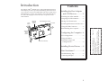
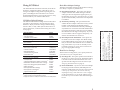
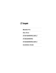
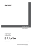
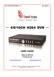
Installation
Guide
AHA-2944UW
AHA-2944UW Installation Guide
Part Number: 511248-00, Rev. A
Page 12 of 12
Print Spec Number: 495686-00
Current Date: 11/13/96
Last Modified: November 13, 1996 12:57 pm
File Location: d:\mario\2944uw.ig\2944uwig.frm
ECN Date: 11/19/96
AAAA
AA
AAAA
A
AA
A
AAAA
AAAAAAAA
AAAAAAAA
AAAAAAAA
AAAAAAA
AAA
AA
A
AA
A
AA
A
AA
A
AA
A
AA
A
AA
A
AA
A
AA
A
AA
A
AA
A
AA
A
AA
A
AA
A
AA
A
AA
A
AA
A
AA
A
AA
A
AA
A
AA
A
AA
A
AA
A
AA
A
AA
A
AA
A
AA
A
AA
A
AA
A
AA
A
AA
A
AA
A
AA
A
AA
A
AA
A
AA
A
AA
A
AA
A
AA
A
AA
A
AA
A
AA
A
AA
A
AA
A
AA
A
AA
A
AA
A
AA
A
AA
AAAA
AAAA
AAAA
AAAA
AAAA
AAA
A
AA AAAAAAAAAAAAAAAAAAA
AAAA
A
Adaptec, Inc.
691 South Milpitas Blvd.
Milpitas, CA 95035
Copyright © 1996, Adaptec, Inc. All rights reserved. No part of
this publication may be reproduced, stored in a retrieval system, or transmitted in any form or by any means, electronic,
mechanical, photocopying, recording or otherwise, without the
prior written consent of Adaptec, Inc., 691 South Milpitas Blvd.,
Milpitas, CA 95035.
Adaptec, the Adaptec logo, AHA, EZ-SCSI, and SCSISelect are
trademarks of Adaptec, Inc. which may be registered in some
jurisdictions. Windows and Windows 95 are registered trademarks, and Windows NT is a trademark, of Microsoft Corporation in the U.S. and other countries used under license. All other
trademarks used are owned by their respective owners.
The material in this document is for information only and is
subject to change without notice. While reasonable efforts have
been made in the preparation of this document to assure its
accuracy, Adaptec, Inc. assumes no liability resulting from
errors or omissions in this document, or from the use of the
information contained herein.
PCI-to-Ultra Wide Differential SCSI Host
Adapter with SCSISelect
Adaptec reserves the right to make changes in the product
design without reservation and without notification to its users.
Printed in Singapore
Stock No.: 511248-00, Rev. A MR 11/96
Information subject to change without notice.
R
Introduction
Contents
AHA®-2944UW
The Adaptec
PCI-to-Ultra Wide Differential SCSI
Host Adapter provides a powerful multitasking interface between
your computer’s PCI bus and differential SCSI devices (disk drives,
CD-ROM drives, scanners, tape backups, removable media drives,
etc.). The following figure shows the major components on the
AHA-2944UW.
Installing the Host Adapter
and SCSI Devices .............. 2
Installing the AHA-2944UW . . . . . . 2
Assigning SCSI ID Numbers . . . . . . 2
68-pin 16-bit
Internal SCSI
Connector
Setting SCSI Termination . . . . . . . . . 2
50-pin 8-bit Internal SCSI Connector
LED Connector
Host
Adapter
LED
68-pin 16-bit
External
SCSI
Connector
Installing Differential SCSI Devices 3
Using the LED Connector . . . . . . . . 4
Reassembling the Computer . . . . . . 4
Configuring the Computer .. 4
PCI Configuration . . . . . . . . . . . . . . 4
Using SCSISelect . . . . . . . . . . . . . . . 5
AIC-78xx SCSI Protocol Chip
Advanced Setups and
Configurations . . . . . . . . . . . . . . . . 8
Installing Device Drivers ..... 9
Need Assistance? .................. 9
Troubleshooting Tips . . . . . . . . . . . . 9
Contacting Adaptec . . . . . . . . . . . . 11
1
AAAA
AA
AAAA
A
AA
A
AAAA
AAAAAAAA
AAAAAAAA
AAAAAAAA
AAAAAAA
AAA
AA
A
AA
A
AA
A
AA
A
AA
A
AA
A
AA
A
AA
A
AA
A
AA
A
AA
A
AA
A
AA
A
AA
A
AA
A
AA
A
AA
A
AA
A
AA
A
AA
A
AA
A
AA
A
AA
A
AA
A
AA
A
AA
A
AA
A
AA
A
AA
A
AA
A
AA
A
AA
A
AA
A
AA
A
AA
A
AA
A
AA
A
AA
A
AA
A
AA
A
AA
A
AA
A
AA
A
AA
A
AA
A
AA
A
AA
A
AA
A
AA
AAAA
AAAA
AAAA
AAAA
AAAA
AAA
A
AA AAAAAAAAAAAAAAAAAAA
AAAA
A
AHA-2944UW Installation Guide
Part Number: 511248-00, Rev. A
Page 1 of 12
Print Spec Number: 495686-00
Current Date: 11/13/96
Last Modified: November 13, 1996 12:57 pm
File Location: d:\mario\2944uw.ig\2944uwig.frm
ECN Date: 11/19/96
Jumpers
J2 and J4
Installing the Host
Adapter and SCSI
Devices
Note: If you plan to boot your computer from a
SCSI device attached to the AHA-2944UW host
adapter, and the device is not assigned the lowest installed SCSI ID, set the Boot Target ID setting in the SCSISelect utility to correspond to the
SCSI ID of the device you are booting from (see
Using SCSISelect on page 5).
Installing the AHA-2944UW
1 Turn OFF power to the computer and peripheral
devices, and disconnect the power cords.
2 Remove the cover from the computer case.
3 Locate an unused 32-bit PCI expansion slot that supports bus master data transfers, then unscrew and
remove the metal bracket that covers the card-slot
opening. (Save the screw to use when securing the
host adapter in your computer.)
PCI slots are shorter than ISA or EISA slots and are
typically white. Usually there are three PCI slots.
(One of these may be a shared slot into which you can
insert either an ISA/EISA board or a PCI board.)
Setting SCSI Termination
SCSI termination is controlled by a set of electrical resistors called terminators. Terminators must be installed (or
enabled) at the two extreme ends of the SCSI bus. All
devices between the ends must have their terminators
removed (or disabled).
Terminating the AHA-2944UW
Termination on the AHA-2944UW itself is controlled by
software commands via the SCSISelect utility. The default
setting is Automatic, which works like this:
■
If the AHA-2944UW detects that a cable is attached to
one SCSI connector, it enables its terminators (the
AHA-2944UW is at the end of the SCSI bus).
■
If the AHA-2944UW detects that cables are attached
to two connectors (either the two internal connectors
or one internal and one external connector) it disables
its terminators (the AHA-2944UW is in the middle of
the SCSI bus).
4 Insert the AHA-2944UW in the PCI slot. Press it down
firmly so that the contacts are securely seated in the
slot.
5 When the AHA-2944UW is firmly seated in the slot,
secure the metal bracket of the host adapter with the
screw you removed in step 3.
Do not replace the computer cover or reconnect your computer and peripherals to their power sources yet!
Assigning SCSI ID Numbers
We recommend that you leave the AHA-2944UW set to
its default setting of Automatic. If you need to manually
set AHA-2944UW termination run the SCSISelect Utility,
as described on page 8, and select a setting as indicated
in this table.
The AHA-2944UW and each device connected to it must
have a unique SCSI ID number ranging from 0 to 15.
We recommend that you leave the AHA-2944UW host
adapter set to its default setting of SCSI ID 7. If you need
to change the AHA-2944UW SCSI ID, see Running
SCSISelect on page 8. If you need to change the SCSI ID
on a hard disk drive or another SCSI device, refer to the
device’s documentation.
2
AHA-2944UW
Termination
Devices Connected to AHA-2944UW
Low
High
68-pin internal connector only
ON
ON
68-pin external connector only
ON
ON
68-pin internal and 68-pin external connectors
OFF
OFF
50-pin internal connector only
ON
ON
50-pin and 68-pin internal connectors
OFF
ON
50-pin internal and 68-pin external connectors
OFF
ON
AAAA
AA
AAAA
A
AA
A
AAAA
AAAAAAAA
AAAAAAAA
AAAAAAAA
AAAAAAA
AAA
AA
A
AA
A
AA
A
AA
A
AA
A
AA
A
AA
A
AA
A
AA
A
AA
A
AA
A
AA
A
AA
A
AA
A
AA
A
AA
A
AA
A
AA
A
AA
A
AA
A
AA
A
AA
A
AA
A
AA
A
AA
A
AA
A
AA
A
AA
A
AA
A
AA
A
AA
A
AA
A
AA
A
AA
A
AA
A
AA
A
AA
A
AA
A
AA
A
AA
A
AA
A
AA
A
AA
A
AA
A
AA
A
AA
A
AA
A
AA
A
AA
AAAA
AAAA
AAAA
AAAA
AAAA
AAA
A
AA AAAAAAAAAAAAAAAAAAA
AAAA
A
AHA-2944UW Installation Guide
Part Number: 511248-00, Rev. A
Page 2 of 12
Print Spec Number: 495686-00
Current Date: 11/13/96
Last Modified: November 13, 1996 12:57 pm
File Location: d:\mario\2944uw.ig\2944uwig.frm
ECN Date: 11/19/96
Follow these instructions to install the AHA-2944UW:
Choosing SCSI Cables
to all three AHA-2944UW connectors.
Terminating SCSI Devices
Read the device’s documentation to determine how to
enable or disable termination on your SCSI device(s). On
most internal SCSI devices the termination setting is controlled by a jumper or a switch. On other internal SCSI
devices you must physically remove or install resistor
modules. On most external SCSI devices, a terminating
plug (a resistor pack embedded in a small plug) is
installed or removed to control termination.
Termination in Multiple Computer
Configurations
If you are setting up your SCSI bus so that SCSI devices
are shared by host adapters in two different computers,
you can enable your host adapter to provide termination
power and enable termination even when one computer
is powered OFF. To do this, place a jumper shunt on
jumper J4 to enable termination and control on data 0-7;
place a jumper shunt on jumper J2 to enable termination
on upper data 8-15 for the powered down computer.
Note: This manual feature will override the
SCSISelect setting for termination control.
Installing Differential SCSI Devices
Caution: The AHA-2944UW host adapter supports only differential SCSI devices. Do not connect single-ended SCSI devices, because they
may damage the host adapter. Read the SCSI
device documentation if you are not sure
whether the device is single-ended or
differential.
You can connect up to fifteen 16-bit Differential Ultra
Wide SCSI devices (internal or external) to the
AHA-2944UW. If you want to combine wide and nonwide SCSI devices, you can connect up to seven 8-bit
internal devices and up to eight 16-bit Wide SCSI devices
(internal or external) to a single AHA-2944UW.
The cables required to connect SCSI devices are determined by the type of devices you are installing, as
described in the following table:
SCSI Device Type
8-bit Internal SCSI
16-bit Internal Wide SCSI
16-bit External Wide SCSI
SCSI Cable type
50-pin internal
68-pin internal
68-pin external
Adaptec sells high-quality internal and external SCSI
cables. If your reseller does not stock these cables, you
can order them directly from Adaptec. (The phone number is listed on page 11.)
Note: To guarantee reliable operation of your
SCSI devices and host adapter, be sure the maximum combined lengths for internal and external SCSI cables does not exceed 25 meters
(82 feet).
Connecting Internal SCSI Devices
If you are connecting internal SCSI devices, make sure
you have an internal SCSI cable with enough connectors
to accommodate all of your devices.
1 Prepare each SCSI device for installation; configure
the device SCSI ID and terminators (terminate the last
internal device attached to the cable). For instructions, see the device’s documentation as well as
Installing the Host Adapter and SCSI Devices on page 2
2 Install the SCSI device in your computer. Refer to
your computer and device documentation for
instructions.
3 Plug the connector at one end of the internal SCSI
cable into one of the host adapter’s internal SCSI
connectors.
Make sure the colored stripe on one side of the cable
is aligned with pin-1 of the host adapter’s connector.
Pin-1 of the connector is usually designated by a
small triangle (▲), or a “1” on the connector.
4 Plug the remaining cable connectors into the connectors on the backs of other SCSI devices (if any).
Make sure the colored stripe on the cable is aligned
with pin-1 of the device’s connector.
3
AAAA
AA
AAAA
A
AA
A
AAAA
AAAAAAAA
AAAAAAAA
AAAAAAAA
AAAAAAA
AAA
AA
A
AA
A
AA
A
AA
A
AA
A
AA
A
AA
A
AA
A
AA
A
AA
A
AA
A
AA
A
AA
A
AA
A
AA
A
AA
A
AA
A
AA
A
AA
A
AA
A
AA
A
AA
A
AA
A
AA
A
AA
A
AA
A
AA
A
AA
A
AA
A
AA
A
AA
A
AA
A
AA
A
AA
A
AA
A
AA
A
AA
A
AA
A
AA
A
AA
A
AA
A
AA
A
AA
A
AA
A
AA
A
AA
A
AA
A
AA
A
AA
AAAA
AAAA
AAAA
AAAA
AAAA
AAA
A
AA AAAAAAAAAAAAAAAAAAA
AAAA
A
AHA-2944UW Installation Guide
Part Number: 511248-00, Rev. A
Page 3 of 12
Print Spec Number: 495686-00
Current Date: 11/13/96
Last Modified: November 13, 1996 12:57 pm
File Location: d:\mario\2944uw.ig\2944uwig.frm
ECN Date: 11/19/96
Note: You cannot attach cables and SCSI devices
power supply) to the power connector on the SCSI
device.
Connecting External SCSI Devices
If you are connecting external SCSI devices to your host
adapter, you must obtain an external SCSI cable for each
external device you install.
1 Prepare each SCSI device for installation; configure
the SCSI ID and attach a terminating plug into the
last external device. For instructions, see the device’s
documentation as well as Installing the Host Adapter
and SCSI Devices on page 2.
2 Plug the connector at one end of the external SCSI
cable into the host adapter’s external SCSI connector.
3 Plug the connector at the other end of the cable into
Configuring the
Computer
PCI Configuration
If your computer does not recognize the host adapter
after you install it (e.g, you receive an error message, or
you cannot access any of the attached SCSI devices), run
the computer’s setup program and check the PCI configuration parameters. Usually you start the setup program
by pressing a specified key combination when your computer boots (refer to your computer’s documentation.)
Here are some things you may need to do in the setup
program.
one of the SCSI connectors on the external SCSI
device.
Note: Some configuration options apply to a
specific PCI bus slot; therefore, if you change
these options be sure you are applying them to
the slot in which the host adapter is installed.
Read your computer documentation if you are
not sure which slot corresponds to each number.
4 To connect other external SCSI devices, daisy-chain
each device to the previous device until all external
SCSI devices have been connected.
Using the LED Connector
(Optional) Most computers have an LED disk activity
light on the front panel. If you disconnect the cable from
the LED connector on the motherboard and connect it to
the LED connector on the host adapter, the LED on the
front panel of the computer will light whenever there is
activity on the SCSI bus.
■
If there is an Interrupt Type or Interrupt Line option
in the setup program, be sure to select Int-A or
Interrupt Type = A. Depending on your system
design, you may also need to change a motherboard
jumper setting.
■
If there is a Triggering Interrupt option, be sure to
select Level.
■
If there is an option to enable or disable bus mastering for the PCI slots, be sure to select Enabled.
■
If there is an option to enable or disable individual
PCI slots, be sure the slot in which you install the host
adapter is enabled.
■
If your computer has a combination of ISA (or EISA)
boards and PCI boards, you may need to mark the
IRQs used by ISA/EISA boards as Used so the system
BIOS will not try to assign these IRQs to other PCI
boards.
■
In some systems the BIOS reserves a set of available
IRQs for PCI boards, and you have to assign these
IRQs manually.
Reassembling the Computer
Be sure all power switches are OFF, then replace the computer chassis cover and reconnect the power cables to
your computer and SCSI devices.
4
AAAA
AA
AAAA
A
AA
A
AAAA
AAAAAAAA
AAAAAAAA
AAAAAAAA
AAAAAAA
AAA
AA
A
AA
A
AA
A
AA
A
AA
A
AA
A
AA
A
AA
A
AA
A
AA
A
AA
A
AA
A
AA
A
AA
A
AA
A
AA
A
AA
A
AA
A
AA
A
AA
A
AA
A
AA
A
AA
A
AA
A
AA
A
AA
A
AA
A
AA
A
AA
A
AA
A
AA
A
AA
A
AA
A
AA
A
AA
A
AA
A
AA
A
AA
A
AA
A
AA
A
AA
A
AA
A
AA
A
AA
A
AA
A
AA
A
AA
A
AA
A
AA
AAAA
AAAA
AAAA
AAAA
AAAA
AAA
A
AA AAAAAAAAAAAAAAAAAAA
AAAA
A
AHA-2944UW Installation Guide
Part Number: 511248-00, Rev. A
Page 4 of 12
Print Spec Number: 495686-00
Current Date: 11/13/96
Last Modified: November 13, 1996 12:57 pm
File Location: d:\mario\2944uw.ig\2944uwig.frm
ECN Date: 11/19/96
5 Connect a DC power cable (from your computer’s
Using SCSISelect
Basic Host Adapter Settings
The basic host adapter settings are the SCSISelect settings
most likely to require any modification.
■
Host Adapter SCSI ID— This option sets the host
adapter’s SCSI ID. The default setting is SCSI ID 7,
which give the host adapter the highest priority on
the SCSI bus (see Assigning SCSI ID Numbers on page
2). We recommend that you leave the host adapter set
to SCSI ID 7.
■
SCSI Parity Checking—This option determines
whether the host adapter verifies the accuracy of data
transfer on the SCSI bus. The default setting is
Enabled. You should disable SCSI Parity Checking if
any SCSI device connected to the AHA-2944UW does
not support SCSI parity; otherwise, leave it enabled.
Most SCSI devices do support SCSI parity. If you are
not sure whether a device supports SCSI parity, consult the documentation for the device.
SCSISelect Default Settings
The default AHA-2944UW settings shown in the following table are appropriate for most SCSI devices. Run
SCSISelect only if you need to change a default setting,
format a disk, or verify a disk. (See the instructions on
page 8.) Otherwise, continue with Installing Device Drivers on page 9.
Basic Host Adapter
Host Adapter SCSI ID
SCSI Parity Checking
Host Adapter SCSI Termination
Boot Device Configuration
Boot Target ID
Boot LUN Number 1
SCSI Device Configuration (0-15)
Initiate Sync Negotiation
Maximum Sync Transfer Rate3
Enable Disconnection
Initiate Wide Negotiation
Send Start Unit SCSI Command 2
Include in BIOS Scan2
Advanced Host Adapter Configuration
Reset SCSI Bus at IC Initialization
Host Adapter BIOS
Support Removable Disks Under BIOS as Fixed Disks2
Extended BIOS Translation for DOS Drives > 1 GByte2
Display <Ctrl-A> Message During BIOS Initialization2
Multiple LUN Support2
BIOS Support for Bootable CD-ROM2
BIOS Support for Int 13 Extensions2
Support for UltraSCSI Speed3
Default
7
Enabled
Automatic
Default
0
0
Default
Yes (Enabled)
20 MBytes/sec
Yes (Enabled)
Yes(Enabled)
No(Disabled)
Yes (Enabled)
Default
Enabled
Enabled
Boot only
Enabled
Enabled
Disabled
Enabled
Enabled
Disabled
1 Setting
is valid only if Multiple LUN Support is enabled
2 Settings are valid only if host adapter BIOS is enabled.
3 If support for UltraSCSI is enabled, the maximum transfer rate is 40 MBytes/Sec.
■
Host Adapter SCSI Termination—This option sets
termination on the host adapter. The default setting
for the AHA-2944UW is Automatic. We recommend
that you leave the AHA-2944UW set to its default setting of Automatic. If you want to manually set the
termination setting, see Setting SCSI Termination on
page 2 for appropriate settings.
Boot Device Settings
The boot device settings allow you to specify the device
you wish to boot your computer from.
■
Boot Target ID—This option specifies the SCSI ID of
the device you wish to boot from. The default setting
is SCSI ID 0. The SCSI ID selected here must correspond to the ID configured on the boot device (see
Assigning SCSI ID Numbers on page 2).
■
Boot LUN Number—If your boot device has multiple
LUNs (Logical Unit Numbers) and Multiple LUN
Support is enabled (see If the Send Start Unit Command
is set to yes for many devices, the boot time will vary
depending how long it takes each drive to start. on page
6), this option allows you to specify which LUN to
boot from on your boot device. The default settings is
LUN 0.
5
AAAA
AA
AAAA
A
AA
A
AAAA
AAAAAAAA
AAAAAAAA
AAAAAAAA
AAAAAAA
AAA
AA
A
AA
A
AA
A
AA
A
AA
A
AA
A
AA
A
AA
A
AA
A
AA
A
AA
A
AA
A
AA
A
AA
A
AA
A
AA
A
AA
A
AA
A
AA
A
AA
A
AA
A
AA
A
AA
A
AA
A
AA
A
AA
A
AA
A
AA
A
AA
A
AA
A
AA
A
AA
A
AA
A
AA
A
AA
A
AA
A
AA
A
AA
A
AA
A
AA
A
AA
A
AA
A
AA
A
AA
A
AA
A
AA
A
AA
A
AA
A
AA
AAAA
AAAA
AAAA
AAAA
AAAA
AAA
A
AA AAAAAAAAAAAAAAAAAAA
AAAA
A
AHA-2944UW Installation Guide
Part Number: 511248-00, Rev. A
Page 5 of 12
Print Spec Number: 495686-00
Current Date: 11/13/96
Last Modified: November 13, 1996 12:57 pm
File Location: d:\mario\2944uw.ig\2944uwig.frm
ECN Date: 11/19/96
The AHA-2944UW includes the onboard, menu-driven
SCSISelect configuration utility, which allows you to
change host adapter settings without opening the computer or handling the board. SCSISelect also contains
SCSI disk utilities that let you low-level format or verify
the disk media of your SCSI hard disk drives.
SCSI Device Settings
■
rate is the maximum rate that the host adapter
accepts from the device during negotiation. (This is
standard SCSI protocol.)
■
Enable Disconnection—This option determines
whether the host adapter allows the SCSI device to
disconnect from the SCSI bus (sometimes called
Disconnect/Reconnect). Enabling disconnection
allows the host adapter to perform other operations
on the SCSI bus while the SCSI device is temporarily
disconnected. The default setting is Yes.
■
Initiate Wide Negotiation— This option determines
whether the host adapter attempts 16-bit data transfer (Wide negotiation) instead of 8-bit data transfer.
The default setting is Yes.
Initiate Sync Negotiation—This option determines
whether the host adapter initiates synchronous data
transfer negotiation (Sync Negotiation) with connected devices. The default setting is Yes.
Synchronous negotiation is a SCSI feature that allows
the host adapter and its connected SCSI devices to
transfer data in synchronous mode. Synchronous
data transfer is faster than asynchronous data
transfer.
The host adapter always responds to Sync Negotiation if a SCSI device initiates it. If neither the host
adapter nor the SCSI device initiate Sync Negotiation,
data is transferred asynchronously.
Note: Some 8-bit SCSI devices have trouble handling Wide negotiation, which may result in
erratic behavior or a hang condition. For these
devices, set Initiate Wide Negotiation to No.
Normally, you should leave the Initiate Sync Negotiation setting enabled, because most SCSI devices support synchronous negotiation and because it allows
for faster data transfer.
When set to Yes, the host adapter attempts 16-bit
transfer. When set to No, 8-bit data transfer is used
unless the SCSI device itself requests Wide negotiation. The effective transfer rate is doubled when
16-bit data transfer is used because the data path for
Wide SCSI is twice the size of normal 8-bit SCSI. For
example, a transfer rate of 10 MBytes/sec becomes 20
MBytes/sec, and a transfer rate of 20 MBytes/sec
(UltraSCSI) becomes 40 MBytes/sec.
Note: Some older SCSI-1 devices do not support
Sync Negotiation. This may cause your computer to operate erratically or hang if Initiate
Sync Negotiation is set to yes. Set Initiate Sync
Negotiation to No for these devices.
■
■
Maximum Sync Transfer Rate—This option sets the
maximum synchronous data transfer rate that the
host adapter supports. The default setting is
20.0 MBytes/sec.
The host adapter supports rates up to the UltraSCSI
maximum of 20.0 MBytes/sec (the AHA-2944UW
provides an effective maximum synchronous transfer
rate of 40.0 MBytes/sec for UltraWide devices). If
your device is an UltraSCSI device, you can use the
maximum value of 20.0 MBytes/sec. If your device is
not an UltraSCSI device select a transfer rate of 10.0
MBytes/sec.
If the host adapter is set not to negotiate for synchronous data transfer (that is, Initiate Sync Negotiation is
set to No), then the maximum synchronous transfer
6
Send Start Unit Command—This option determines
whether the Start Unit Command is sent to the SCSI
device at bootup (most devices do not require this).
The default setting is No.
Setting this option to yes reduces the load on your
computer’s power supply by allowing the host
adapter to start SCSI devices one-at-a-time when you
boot your computer. When set to no, the devices are
allowed to start at the same time. Most devices
require you to set a jumper before they can respond to
this command.
Note: If the Send Start Unit Command is set to
yes for many devices, the boot time will vary
depending how long it takes each drive to start.
AAAA
AA
AAAA
A
AA
A
AAAA
AAAAAAAA
AAAAAAAA
AAAAAAAA
AAAAAAA
AAA
AA
A
AA
A
AA
A
AA
A
AA
A
AA
A
AA
A
AA
A
AA
A
AA
A
AA
A
AA
A
AA
A
AA
A
AA
A
AA
A
AA
A
AA
A
AA
A
AA
A
AA
A
AA
A
AA
A
AA
A
AA
A
AA
A
AA
A
AA
A
AA
A
AA
A
AA
A
AA
A
AA
A
AA
A
AA
A
AA
A
AA
A
AA
A
AA
A
AA
A
AA
A
AA
A
AA
A
AA
A
AA
A
AA
A
AA
A
AA
A
AA
AAAA
AAAA
AAAA
AAAA
AAAA
AAA
A
AA AAAAAAAAAAAAAAAAAAA
AAAA
A
AHA-2944UW Installation Guide
Part Number: 511248-00, Rev. A
Page 6 of 12
Print Spec Number: 495686-00
Current Date: 11/13/96
Last Modified: November 13, 1996 12:57 pm
File Location: d:\mario\2944uw.ig\2944uwig.frm
ECN Date: 11/19/96
The SCSI device settings allow you to configure certain
parameters for each device on the SCSI bus. To configure
a specific device, you must know the SCSI ID assigned to
that device. If you are not sure of the SCSI ID, see Using
the SCSI Disk Utilities on page 8.
Include in BIOS Scan—This option determines
whether Int 13h devices (hard disk drives) attached to
the SCSI bus are recognized by the host adapter BIOS
and are installed as devices on the system without the
need for device driver software.
Caution: If a removable-media SCSI device is
controlled by the host adapter BIOS, do not
remove the media while the drive is on or you
may lose data! If you want to be able to remove
media while the drive is on, install your removable-media device driver and set this option to
Disabled.
Advanced Host Adapter Settings
The advanced host adapter settings should not be
changed unless absolutely necessary.
■
■
Reset SCSI Bus at IC Initialization—This option
allows you to enable or disable SCSI bus resets generated by the host adapter during power-on initialization and after a hard reset. The default setting is
Enabled.
■
Host Adapter BIOS—This option enables or disables
the host adapter BIOS. The default setting is Enabled.
Caution: If you decide to change the translation
scheme, back up your disk drives first! All data
is erased when you change from one translation
scheme to another.
Note: Several SCSISelect options are not valid
unless the host adapter BIOS is enabled. See the
table on page 5.
■
Extended BIOS Translation for DOS Drives > 1
GByte—This option determines whether extended
translation is available for SCSI hard disks with
capacities greater than 1 GByte. The default setting is
Enabled.
If you are booting from a SCSI disk drive connected
to the host adapter, the BIOS must be enabled. You
should disable the host adapter BIOS if the peripherals on the SCSI bus (for example, CD-ROM drives)
are all controlled by device drivers and do not need
the BIOS.
The standard translation scheme for SCSI host adapters provides a maximum accessible capacity of
1 GByte. To support disk drives larger than 1 GByte,
the AHA-2944UW includes an extended translation
scheme. This scheme supports disk drives as large as
8 GBytes under MS-DOS with a maximum partition
size of 2 GBytes.
Support Removable Disks Under BIOS as Fixed
Disks—This option controls which removable-media
drives are supported by the host adapter BIOS. The
default setting is Boot Only. The following choices are
available:
Extended BIOS Translation is used only with
MS-DOS 5.0 or above. You do not need to enable this
option if you are using another operating system
such as NetWare, OS/2, Windows NT™, or UNIX.
–
Boot Only—Only the removable-media drive
designated as the boot device is treated as a hard
disk drive.
–
All Disks—All removable-media drives supported by the BIOS are treated as hard disk
drives.
–
Disabled— No removable-media drives are
treated as hard disk drives. In this situation, software drivers are needed because the drives are
not controlled by the BIOS.
When you partition a disk larger than 1 GByte, use
the MS-DOS fdisk utility as you normally would.
Because the cylinder size increases to 8 MBytes under
extended translation, the partition size you choose
must be a multiple of 8 MBytes. If you request a size
that is not a multiple of 8 MBytes, fdisk rounds up to
the nearest whole multiple of 8 MBytes.
■
Display <Ctrl-A> Message During BIOS Initialization—This option determines whether the message
Press <Ctrl> <A> for SCSISelect (TM) Utility!
appears on your screen during system bootup. The
default setting is Enabled. If this setting is disabled,
you can still invoke the SCSISelect utility by pressing
7
AAAA
AA
AAAA
A
AA
A
AAAA
AAAAAAAA
AAAAAAAA
AAAAAAAA
AAAAAAA
AAA
AA
A
AA
A
AA
A
AA
A
AA
A
AA
A
AA
A
AA
A
AA
A
AA
A
AA
A
AA
A
AA
A
AA
A
AA
A
AA
A
AA
A
AA
A
AA
A
AA
A
AA
A
AA
A
AA
A
AA
A
AA
A
AA
A
AA
A
AA
A
AA
A
AA
A
AA
A
AA
A
AA
A
AA
A
AA
A
AA
A
AA
A
AA
A
AA
A
AA
A
AA
A
AA
A
AA
A
AA
A
AA
A
AA
A
AA
A
AA
A
AA
AAAA
AAAA
AAAA
AAAA
AAAA
AAA
A
AA AAAAAAAAAAAAAAAAAAA
AAAA
A
AHA-2944UW Installation Guide
Part Number: 511248-00, Rev. A
Page 7 of 12
Print Spec Number: 495686-00
Current Date: 11/13/96
Last Modified: November 13, 1996 12:57 pm
File Location: d:\mario\2944uw.ig\2944uwig.frm
ECN Date: 11/19/96
■
■
■
■
■
Multiple LUN Support—This option determines
whether booting from a SCSI device that has multiple
LUNs is supported. The default setting is Disabled.
Enable this option if your boot device has multiple
LUNs.
BIOS Support for Bootable CD-ROM—This option
determines whether the host adapter BIOS provides
support for booting from a CD-ROM drive. The
default setting is Enabled.
BIOS Support for Int 13 Extensions—This option
determines whether the host adapter BIOS supports
disks with more than 1024 cylinders. The default setting is Enabled.
To access the SCSI disk utilities, select the SCSI Disk Utilities option from the Options menu that appears when you
start SCSISelect. SCSISelect immediately scans the SCSI bus
and displays a list of all SCSI IDs and the devices assigned
to each ID.
When you select a specific ID and device, a small menu
appears, displaying the options Format Disk and Verify
Disk Media.
■
Format Disk—This utility allows you to perform a
low-level format on a hard disk drive. Most SCSI disk
devices are preformatted at the factory and do not
need to be formatted again. The Adaptec Format Disk
utility is compatible with nearly all SCSI disk drives.
■
Verify Disk Media—This utility allows you to scan
the media of a hard disk drive for defects. If the utility finds bad blocks on the media, it prompts you to
reassign them; if you select Yes, those blocks are no
longer used. You can press Esc at any time to abort
the utility.
Support for UltraSCSI Speed—This option determines whether the host adapter supports the fast
transfer rates of UltraSCSI devices. The default setting is Disabled.
Running SCSISelect
To start the SCSISelect utility, press Ctrl-A when the following prompt appears at boot time:
Press <Ctrl><A> for SCSISelect (TM) Utility!
When the Options menu appears, select Configure/View
Host Adapter Settings or SCSI Disk Utilities.
SCSISelect uses menus to list options you can select. To
select an option, use the ↑ and ↓ keys to move the cursor
to the option, then press Enter.
In some cases, selecting an option displays another menu.
You can return to the previous menu at any time by pressing Esc. To restore the original SCSISelect default values,
press F6. To toggle the display between color and monochrome modes, press F5 (this feature does not work on
some monitors).
To exit SCSISelect, press Esc until a message prompts
you to exit. If you changed any options, you are
prompted to save the changes before you exit. At the
prompt, select Yes to exit, then press any key to reboot
the computer. Any changes you made in SCSISelect take
effect after the computer boots.
8
Using the SCSI Disk Utilities
Advanced Setups and
Configurations
Configuring Multiple Host Adapters
Multiple AHA-2944UW host adapters can be installed in
your computer; you are limited only by the number of
available PCI bus slots (installation and setup is the same
as a single AHA-2944UW). Each host adapter you install
forms a separate SCSI bus with a different set of SCSI
devices.
In computers with multiple host adapters, consider the
following:
■
If you are booting from the AHA-2944UW, you may
need to install the boot host adapter in the lowest
numbered PCI bus slot. (Most PCI systems do not
have this requirement.) Refer to your system documentation to determine the PCI bus slot number.
■
If you have two AHA-2944UW host adapters and
each has a boot device connected, the computer boots
from the host adapter in the lowest numbered PCI
bus slot. If you want to select a specific host adapter
to boot from, enable the BIOS only on that host
adapter.
AAAA
AA
AAAA
A
AA
A
AAAA
AAAAAAAA
AAAAAAAA
AAAAAAAA
AAAAAAA
AAA
AA
A
AA
A
AA
A
AA
A
AA
A
AA
A
AA
A
AA
A
AA
A
AA
A
AA
A
AA
A
AA
A
AA
A
AA
A
AA
A
AA
A
AA
A
AA
A
AA
A
AA
A
AA
A
AA
A
AA
A
AA
A
AA
A
AA
A
AA
A
AA
A
AA
A
AA
A
AA
A
AA
A
AA
A
AA
A
AA
A
AA
A
AA
A
AA
A
AA
A
AA
A
AA
A
AA
A
AA
A
AA
A
AA
A
AA
A
AA
A
AA
AAAA
AAAA
AAAA
AAAA
AAAA
AAA
A
AA AAAAAAAAAAAAAAAAAAA
AAAA
A
AHA-2944UW Installation Guide
Part Number: 511248-00, Rev. A
Page 8 of 12
Print Spec Number: 495686-00
Current Date: 11/13/96
Last Modified: November 13, 1996 12:57 pm
File Location: d:\mario\2944uw.ig\2944uwig.frm
ECN Date: 11/19/96
<Ctrl><A> after the host adapter BIOS banner
appears.
If you are booting from the AHA-2944UW and you
also have an ISA/EISA-based host adapter installed,
you must disable the BIOS on the ISA/EISA-based
host adapter.
■
If you are booting from an ISA/EISA-based host
adapter and you also have an AHA-2944UW
installed with a boot device connected, the ISA/
EISA-based host adapter will boot before the
AHA-2944UW.
■
When running the SCSISelect utility, if the utility finds
multiple AHA-2944UW host adapters in your computer, it displays the PCI bus number and PCI device
number of each host adapter. To determine which of
the host adapters SCSISelect is configuring, view the
red LEDs on the host adapters as you move the highlight bar to different host adapters with the ↑ and ↓
keys. (The computer cover must be removed to view
the LEDs.)
Installing Device
Drivers
Some operating systems have an embedded driver for the
AHA-2940UW. These drivers work fine with your
AHA-2944UW; however, the most recent version of the
driver should be installed in order for your AHA-2944UW
to perform at its optimum level.
If you purchased your AHA-2944UW in a kit, the kit
includes the latest Adaptec EZ-SCSI® and Adaptec 7800
Family Manager Set software.
■
■
Adaptec EZ-SCSI—allows you to install software
drivers for DOS/Windows® and several additional
utilities. Refer to the EZ-SCSI Quick Reference.
Adaptec 7800 Family Manager Set—allows you to
install software drivers for NetWare, OS/2, Windows® 95, Windows NT, and UNIX. Refer to the 7800
Family Manager Set User’s Guide.
You can order EZ-SCSI or the 7800 Family Manager Set
by calling the number listed on page 11.
Need Assistance?
Troubleshooting Tips
If you have a problem during installation, check these
items first:
■
Have you installed the host adapter in a PCI Rev 2.0
compliant computer?
■
Are all SCSI devices powered?
■
Are all SCSI bus cables and power cables properly
connected? Is pin 1 oriented correctly?
■
Does the host adapter and all devices on the SCSI bus
have unique SCSI IDs?
■
Is pin-1 orientation maintained throughout the SCSI
bus? (See Connecting Internal SCSI Devices on page 3.)
■
Are all devices on the SCSI bus terminated
properly?
■
Does your system CMOS setup require you to enable
PCI bus parameters? If so, see your computer’s documentation. Check that IRQ channel assignment,
board, and BIOS settings have been made.
■
Did you install your host adapter in a bus master PCI
slot? Refer to your computer’s documentation or try
another slot.
■
Is parity checking consistently enabled or disabled on
all devices on the SCSI bus?
Computer Will Not Boot from a SCSI Disk
Drive
If both SCSI and non-SCSI disk drives are installed, then
the non-SCSI disk drive is always the boot device. If the
system has only SCSI disk drives, do the following:
1 Make sure the drive type in your computer’s CMOS
setup is set to No Drives Installed.
2 Make sure the boot hard disk SCSI ID corresponds to
the Boot Target ID setting in SCSISelect. The SCSI ID
is normally set with jumpers or switches on the drive.
3 If this does not solve the problem, back up all data on
the SCSI hard disk and perform a low-level format
with the SCSISelect Format Disk option. See the
MS-DOS documentation for instructions on partitioning the disk after formatting.
9
AAAA
AA
AAAA
A
AA
A
AAAA
AAAAAAAA
AAAAAAAA
AAAAAAAA
AAAAAAA
AAA
AA
A
AA
A
AA
A
AA
A
AA
A
AA
A
AA
A
AA
A
AA
A
AA
A
AA
A
AA
A
AA
A
AA
A
AA
A
AA
A
AA
A
AA
A
AA
A
AA
A
AA
A
AA
A
AA
A
AA
A
AA
A
AA
A
AA
A
AA
A
AA
A
AA
A
AA
A
AA
A
AA
A
AA
A
AA
A
AA
A
AA
A
AA
A
AA
A
AA
A
AA
A
AA
A
AA
A
AA
A
AA
A
AA
A
AA
A
AA
A
AA
AAAA
AAAA
AAAA
AAAA
AAAA
AAA
A
AA AAAAAAAAAAAAAAAAAAA
AAAA
A
AHA-2944UW Installation Guide
Part Number: 511248-00, Rev. A
Page 9 of 12
Print Spec Number: 495686-00
Current Date: 11/13/96
Last Modified: November 13, 1996 12:57 pm
File Location: d:\mario\2944uw.ig\2944uwig.frm
ECN Date: 11/19/96
■
■
If you changed any values on a host adapter, in a
setup program, or on a SCSI device, did you turn the
power OFF and ON to ensure that the new values are
loaded?
■
If you tried to use the format/verify utility on a disk
device and got an Unexpected SCSI Command Failure pop-up box with error information, the utility
probably encountered a problem with the disk device
or the media and therefore cannot run.
You can probably determine from the Sense Key
information (e.g., 06h - Unit Attention) both the cause
of the problem and its solution. Here are some of the
more common Sense Key values and their meanings:
–
02h - Not ready—The media is not ready to format. Be sure that media is inserted in the drive
and that the media is spun up.
–
03h - Medium error—The disk media may be
defective. If it is a removable-media drive, try
using a different disk media. If it is a hard disk
drive, the disk may be physically damaged. Verify
and format the media with SCSISelect.
–
04h - Hardware error—The disk drive may be
defective. Consult the hardware documentation
and contact the manufacturer.
–
06h - Unit attention—The removable media may
be write-protected. Disable write protection and
run the utility again.
BIOS Startup Messages
If the host adapter BIOS is enabled, but it fails to initialize, the system displays a specific error message followed
by a BIOS Installation Failure message. Here are some of
these error messages and their meaning:
Device connected, but not ready.
The host adapter received no answer when it requested
data from an installed SCSI device. Try setting the Send
Start Unit Command to Yes for the host adapter.
If the message still appears, follow the drive manufacturer’s instructions to make sure the drive is set to spin
up when the power is switched ON.
10
Start unit request failed.
The BIOS was unable to send a Start Unit Command to
the device. Run the SCSISelect utility and disable Send
Start Unit Command for the device.
Time-out failure during …
An unexpected time-out occurred. Check SCSI bus termination. Try disconnecting the SCSI peripheral cables from
the host adapter and then starting the computer. If the
computer successfully restarts, check SCSI bus termination and cable connections. One of the devices on the
SCSI bus may be defective.
AAAA
AA
AAAA
A
AA
A
AAAA
AAAAAAAA
AAAAAAAA
AAAAAAAA
AAAAAAA
AAA
AA
A
AA
A
AA
A
AA
A
AA
A
AA
A
AA
A
AA
A
AA
A
AA
A
AA
A
AA
A
AA
A
AA
A
AA
A
AA
A
AA
A
AA
A
AA
A
AA
A
AA
A
AA
A
AA
A
AA
A
AA
A
AA
A
AA
A
AA
A
AA
A
AA
A
AA
A
AA
A
AA
A
AA
A
AA
A
AA
A
AA
A
AA
A
AA
A
AA
A
AA
A
AA
A
AA
A
AA
A
AA
A
AA
A
AA
A
AA
A
AA
AAAA
AAAA
AAAA
AAAA
AAAA
AAA
A
AA AAAAAAAAAAAAAAAAAAA
AAAA
A
AHA-2944UW Installation Guide
Part Number: 511248-00, Rev. A
Page 10 of 12
Print Spec Number: 495686-00
Current Date: 11/13/96
Last Modified: November 13, 1996 12:57 pm
File Location: d:\mario\2944uw.ig\2944uwig.frm
ECN Date: 11/19/96
Other Problems and Solutions
Contacting Adaptec
Federal Communications Commission Radio Frequency
Interference Statement
If you have questions about installing or using your Adaptec
product, check this installation guide first—you will find
answers to most of your questions here. If you need further
assistance, please contact us. We offer the following support
and information services:
WARNING: Changes or modifications to this unit not expressly approved
by the party responsible for compliance could void the user ’s authority to
operate the equipment.
Technical information, including product literature, answers to
commonly asked questions, information on software upgrades
and other topics is available electronically through the
following:
■
Adaptec World Wide Web (WWW) site at
http://www.adaptec.com.
■
Reorient or relocate the receiving antenna.
■
File Transfer Protocol (FTP) server at ftp.adaptec.com.
■
Increase the separation between equipment and receiver.
■
CompuServe Adaptec Forum at GO ADAPTEC.
■
■
Adaptec USA Bulletin Board Service (BBS) at 408-945-7727;
supports up to 28,800 bps (bits per second), 8 data bits,
1 stop bit, no parity. No product literature is available on the
Adaptec BBS.
Connect the equipment to an outlet on a circuit different from that to
which the receiver is connected.
■
Interactive Fax System at 408-957-7150.
Technical and Product Support
■
■
■
For technical support and information about many of
Adaptec’s electronic support services, call 800-959-7274 or
408-945-2550, 24 hours a day, 7 days a week.
To use the Adaptec Interactive Support System, call
800-959-7274 or 408-945-2550, 24 hours a day, 7 days a week.
The system prompts you with questions regarding your
problem and then provides step-by-step troubleshooting
instructions.
Consult the dealer or an experienced radio/television technician for
help.
Use a shielded and properly grounded I/O cable and power cable to
ensure compliance of this unit to the specified limits of the rules.
■
This device complies with part 15 of the FCC rules. Operation is subject to
the following two conditions: (1) this device may not cause harmful interference and (2) this device must accept any interference received, including interference that may cause undesired operation.
Canadian Compliance Statement
This Class B digital apparatus meets all requirements of the Canadian
Interference-Causing Equipment Regulations.
Cet appareil numérique de la classe B respecte toutes les exigences du
Règlement sur le matérial brouilleur du Canada.
To speak with a product support representative, call
408-934-7274, M–F, 6:00 A.M . to 5:00 P.M., Pacific Time.
After hours, on weekends, and on holidays, product support
is also available for a fee at 800-416-8066.
Sales and Ordering Information
■
For sales information, call 800-959-7274 or 408-945-2550,
M–F, 6:00 A.M. to 5:00 P.M ., Pacific Time.
■
To order Adaptec software and SCSI cables, call 800-442-7274
or 408-957-7274, M–F, 6:00 A.M. to 5:00 P.M ., Pacific Time.
■
To request additional documentation for Adaptec products,
call 800-934-2766 or 510-732-3829, M–F, 6:00 A.M. to 5:00 P.M.,
Pacific Time.
❒
11
AAAA
AA
AAAA
A
AA
A
AAAA
AAAAAAAA
AAAAAAAA
AAAAAAAA
AAAAAAA
AAA
AA
A
AA
A
AA
A
AA
A
AA
A
AA
A
AA
A
AA
A
AA
A
AA
A
AA
A
AA
A
AA
A
AA
A
AA
A
AA
A
AA
A
AA
A
AA
A
AA
A
AA
A
AA
A
AA
A
AA
A
AA
A
AA
A
AA
A
AA
A
AA
A
AA
A
AA
A
AA
A
AA
A
AA
A
AA
A
AA
A
AA
A
AA
A
AA
A
AA
A
AA
A
AA
A
AA
A
AA
A
AA
A
AA
A
AA
A
AA
A
AA
AAAA
AAAA
AAAA
AAAA
AAAA
AAA
A
AA AAAAAAAAAAAAAAAAAAA
AAAA
A
AHA-2944UW Installation Guide
Part Number: 511248-00, Rev. A
Page 11 of 12
Print Spec Number: 495686-00
Current Date: 11/13/96
Last Modified: November 13, 1996 12:57 pm
File Location: d:\mario\2944uw.ig\2944uwig.frm
ECN Date: 11/19/96
Electronic Support
This equipment has been tested and found to comply with the limits for a
Class B digital device, pursuant to Part 15 of the FCC rules. These limits
are designed to provide reasonable protection against harmful interference in a residential installation. This equipment generates, uses, and can
radiate radio frequency energy, and if not installed and used in accordance with the instruction manual, may cause harmful interference to
radio communications. However, there is no guarantee that interference
will not occur in a particular installation. However, if this equipment does
cause interference to radio or television equipment reception, which can
be determined by turning the equipment off and on, the user is encouraged to try to correct the interference by one or more of the following
measures: