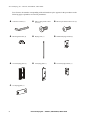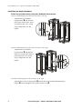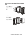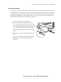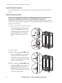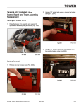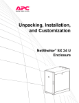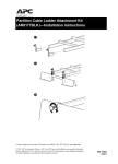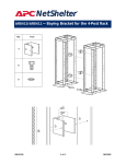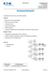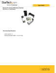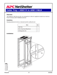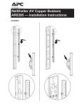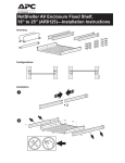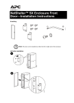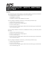
1
External Baying Kit —AR8376, AR8376BLK,
AR8377BLK
Overview
The External Baying Kit contains hardware to join together NetShelter VS (900mm) and NetShelter
VX (1070mm) enclosures. Using this hardware kit, you can join together:
• two NetShelter VS enclosures
• two NetShelter VX enclosures
• a NetShelter VS enclosure and a NetShelter VX enclosure
If you are joining two NetShelter VS enclosures, you will need to perform these steps:
1. Install the front baying hardware (page 3).
2. Install the rear baying hardware and plate (page 4).
3. Level the enclosures (page 7).
4. Connect the enclosures together (page 8). Make the front connections (page 8), and then make
the rear connections (page 9).
If you are joining a NetShelter VX enclosure to a NetShelter VS enclosure, you will need to perform
these steps:
1. Install the front baying hardware (page 3).
2. Install the rear baying hardware and plate (page 5).
3. Level the enclosures (page 7).
4. Connect the enclosures together (page 8). Make the front connections (page 8), and then make
the rear connections (page 9).
If you are joining two NetShelter VX enclosures, you will need to perform these steps:
1. Install the front baying hardware (page 3).
2. Level the enclosures (page 7).
3. Connect the enclosures together (page 8). Make the front connections (page 8), and then make
the rear connections (page 10).
External Baying Kit —AR8376, AR8376BLK, AR8377BLK
For reference, the number corresponding with each hardware piece appears in the procedures on the
following pages. Quantities are listed in parentheses.
3-mm hex wrench (1)
M6x12 low-profile socket
screw (6)
M6x12 pan-head socket screw (6)
M6 flanged hex nut (6)
Baying trim (1)
Standard baying bracket (6)
VX-VS baying plate (1)
VS baying plate (1)
VX-VS baying bracket (1)
VX baying plate (1)
2
External Baying Kit — AR8376, AR8376BLK, AR8377BLK
External Baying Kit —AR8376, AR8376BLK, AR8377BLK
Install the front baying hardware
Follow this procedure when joining two NetShelter VS enclosures, a NetShelter VX
enclosure to a NetShelter VS enclosure, or two NetShelter VX enclosures.
Attach a baying bracket to the enclosure on the right:
1. Align the hole in a standard
baying bracket with the hole
near the top of the left vertical
frame. Insert a pan-head socket
screw , fasten using a flanged
hex nut , and tighten using the
3-mm hex wrench (provided).
2. Align the hole in a standard
baying bracket with the hole
near the bottom of the left vertical
frame. Secure as in step 1.
Attach a baying bracket to the enclosure on the left:
3. Align the hole in a standard
baying bracket with the hole
near the top of the right vertical
frame. Secure as in step 1.
4. Align the hole in a standard
baying bracket with the hole
near the bottom of the right
vertical frame. Secure as in step 1.
External Baying Kit — AR8376, AR8376BLK, AR8377BLK
3
External Baying Kit —AR8376, AR8376BLK, AR8377BLK
Install the rear baying hardware
Follow this procedure when joining two NetShelter VS enclosures.
Attach a standard baying bracket to the enclosure on the left:
Align the hole in a standard
baying bracket with the hole
in the right vertical frame. Insert
a pan-head socket screw, fasten
using a flanged hex nut, and
tighten.
Attach a standard baying bracket to the enclosure on the right:
Align the hole in a standard
baying bracket with the hole
in the left vertical frame. Insert a
pan-head socket screw, fasten
using a flanged hex nut, and
tighten.
Attach the VS baying plate to the enclosure on the right:
Align the hole in the VS baying plate with the hole in the installed standard baying
bracket . Insert and tighten a low-profile socket screw .
4
External Baying Kit — AR8376, AR8376BLK, AR8377BLK
External Baying Kit —AR8376, AR8376BLK, AR8377BLK
Follow this procedure when joining a NetShelter VX enclosure to a NetShelter VS
enclosure.
Attach a standard baying bracket to the enclosure on the left:
Align the hole in a standard
baying bracket with the hole
in the right vertical frame. Insert
a pan-head socket screw, fasten
using a flanged hex nut, and
tighten.
Attach the VX-VS baying bracket to the enclosure on the right:
Align the hole in VX-VS
baying bracket with the
hole in the left vertical frame.
Insert a pan-head socket
screw, fasten using a flanged
hex nut, and tighten.
External Baying Kit — AR8376, AR8376BLK, AR8377BLK
5
External Baying Kit —AR8376, AR8376BLK, AR8377BLK
Attach the VX-VS baying plate to the enclosure on the right:
Align the hole in the VX-VS
baying plate with the hole
in the installed VX-VS
baying bracket. Insert and
tighten a low-profile socket
screw.
6
External Baying Kit — AR8376, AR8376BLK, AR8377BLK
External Baying Kit —AR8376, AR8376BLK, AR8377BLK
Level the enclosures
The first step is to slide the enclosures together and align. Follow these procedures to make certain
the enclosures are level with each other. Leveling feet are attached under the enclosure at each corner.
The leveling feet can help provide a stable base if the selected floor space is uneven, but they are not
intended to compensate for a badly sloped surface. You can remove the casters and leveling feet to
allow the base of the enclosure to rest directly on the floor.
1. Move the enclosure to a level location.
2. Fit the 14-mm end of the open-ended wrench
(provided with your enclosure) to the hex head just
above the round pad on the bottom of the leveling
foot. Turn the wrench clockwise to extend the
leveling foot until it makes firm contact with the
floor.
3. Repeat step 2 for each of the remaining leveling
feet.
4. Use a level to determine which feet need further
adjustment to level the enclosure. Adjust as
necessary.
oln
External Baying Kit — AR8376, AR8376BLK, AR8377BLK
7
External Baying Kit —AR8376, AR8376BLK, AR8377BLK
Connect enclosures together
The connection procedure varies according to your enclosure configuration: 24-inch or 600-mm
centers.
Make the front connections
Follow this procedure when joining two NetShelter VS enclosures, a NetShelter VX
enclosure to a NetShelter VS enclosure, or two NetShelter VX enclosures.
Each illustration shows connections for two NetShelter VS enclosures, but the steps are identical
whether you are joining together a NetShelter VX enclosure and a NetShelter VS enclosure, or two
NetShelter VX enclosures.
Attach the baying trim to the enclosure on the left:
Align the holes at the top and bottom of
the baying trim with the holes in the
standard baying brackets attached to the
right side of the enclosure on the left.
Insert and tighten a low-profile socket
screw.
Attach the enclosures:
Enclosures configured on 24-inch D centers:
Align the hole D at the top and bottom of
the baying trim with the holes in the
standard baying brackets attached to the
enclosure. Insert and tighten a low-profile
socket screw into each hole.
-
,
Enclosures configured on 600-mm E centers:
Align the hole E at the top and bottom of
the baying trim with the holes in the
standard baying brackets attached to the
enclosure. Insert and tighten a low-profile
socket screw into each hole.
8
External Baying Kit — AR8376, AR8376BLK, AR8377BLK
External Baying Kit —AR8376, AR8376BLK, AR8377BLK
Make the rear connections
Follow this procedure when joining two NetShelter VS enclosures.
Enclosures configured on 24-inch D
centers:
Align the left hole D in the VS
baying plate with the hole in the
standard baying bracket. Insert and
tighten a low-profile screw.
,
-
Enclosures configured on 600-mm E
centers:
Align the right hole E in the VS
baying plate with the hole in the
standard baying bracket. Insert and
tighten a low-profile screw.
Follow this procedure when joining a NetShelter VX enclosure to a NetShelter VS
enclosure.
Enclosures configured on 24-inch D centers:
Align the left hole D in the VX-VS
baying plate with the hole in the
standard baying bracket. Insert and
tighten a low-profile screw.
,
-
Enclosures configured on 600-mm E centers:
Align the right hole E in the VX-VS
baying plate with the hole in the
standard baying bracket. Insert and
tighten a low-profile screw.
External Baying Kit — AR8376, AR8376BLK, AR8377BLK
9
External Baying Kit —AR8376, AR8376BLK, AR8377BLK
Follow this procedure when joining two NetShelter VX enclosures.
Enclosures configured on 24-inch D
centers:
1. Align the hole D in the VX baying
plate with the hole in the right
vertical frame of the enclosure to
the left. Insert and tighten a lowprofile screw.
,
-
.
2. Align the hole F in the VX baying
plate with the hole in the left
vertical frame of the enclosure to
the right. Insert and tighten a lowprofile screw.
Enclosures configured on 600-mm E centers:
1. Align the hole E of the VX baying plate with the hole in the right vertical frame of the
enclosure to the left. Insert and tighten a low-profile screw.
2. Align the hole F of the VX baying plate with the hole in the left vertical frame of the
enclosure to the right. Insert and tighten a low-profile screw.
10
External Baying Kit — AR8376, AR8376BLK, AR8377BLK
nv
APC Worldwide Customer Support
Customer support for this or any other APC product is available at no charge in any of the following ways:
• Visit the APC Web site to find answers to frequently asked questions (FAQs), to access documents in the APC
Knowledge Base, and to submit customer support requests.
– www.apc.com (Corporate Headquarters)
Connect to localized APC Web sites for specific countries, each of which provides customer support
information.
– www.apc.com/support/
Global support with FAQs, knowledge base, and e-support.
• Contact an APC Customer Support center by telephone or e-mail.
– Regional centers:
APC headquarters U.S., Canada
Latin America
Europe, Middle East, Africa
(1)(800)800-4272 (toll free)
(1)(401)789-5735 (USA)
(353)(91)702020 (Ireland)
(0) 35434-2021
Japan
– Local, country-specific centers: go to www.apc.com/support/contact for contact information.
Contact the APC representative or other distributor from whom you purchased your APC product for information on
how to obtain local customer support.
Entire contents copyright © 2003 American Power Conversion. All rights reserved.
Reproduction in whole or in part without permission is prohibited. APC, the APC logo,
NetShelter, and InfraStruXure are trademarks of American Power Conversion Corporation and
may be registered in some jurisdictions. All other trademarks, product names, and corporate
names are the property of their respective owners and are used for informational purposes only.
990-1398A
04/2003