1
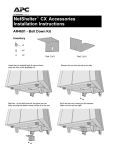
NetShelter® VX Enclosure Unpacking, Installation, Customization This manual is available in English on the enclosed CD. Dieses Handbuch ist in Deutsch auf der beiliegenden CD-ROM verfügbar. Este manual está disponible en español en el CD-ROM adjunto. Ce manuel est disponible en français sur le CD-ROM ci-inclus. Questo manuale è disponibile in italiano nel CD-ROM allegato. Contents Product Description and Inventory ...........................1 Product description . . . . . . . . . . . . . . . . . . . . . . . . . . . . . . 1 NetShelter VX enclosures . . . . . . . . . . . . . . . . . . . . . . . . . . 1 Product Inventory . . . . . . . . . . . . . . . . . . . . . . . . . . . . . . . . . . . 2 Features of the enclosure . . . . . . . . . . . . . . . . . . . . . . . . . . 2 Hardware, grommets, and covers . . . . . . . . . . . . . . . . . . . . . 3 Before Installation . . . . . . . . . . . . . . . . . . . . . . . . . . . . . . . . . . . 4 Location of keys and mounting hardware . . . . . . . . . . . . . . . 4 Tools provided . . . . . . . . . . . . . . . . . . . . . . . . . . . . . . . . . 4 Tools required . . . . . . . . . . . . . . . . . . . . . . . . . . . . . . . . . . 4 Packaging of the enclosure . . . . . . . . . . . . . . . . . . . . . . . . . 5 How to unpack the enclosure . . . . . . . . . . . . . . . . . . . . . . . 6 Please recycle . . . . . . . . . . . . . . . . . . . . . . . . . . . . . . . . . . 6 Disclaimer . . . . . . . . . . . . . . . . . . . . . . . . . . . . . . . . . . . . 6 Take inventory . . . . . . . . . . . . . . . . . . . . . . . . . . . . . . . . . 6 Configuration . . . . . . . . . . . . . . . . . . . . . . . . . . . . . . . . . . 7 How to install the NetShelter VX Enclosure . . . . . . . . . . . . . . . . 8 How to level the enclosure . . . . . . . . . . . . . . . . . . . . . . . . . 8 How to remove the casters and leveling feet (optional) . . . . . . 8 Stabilizing kits (optional) . . . . . . . . . . . . . . . . . . . . . . . . . . 9 How to Remove and Install the Side Panels . . . . . . . . . . . . . . . 10 How to Remove the Roof . . . . . . . . . . . . . . . . . . . . . . . . . . . . 12 How to Reverse the Front Door . . . . . . . . . . . . . . . . . . . . . . . . 13 Vertical Mounting Rails . . . . . . . . . . . . . . . . . . . . . . . . . . . . . . 19 How to adjust the mounting rails on the frame posts . . . . . . 19 How to re-position the vertical rails using the horizontal braces 20 How to Mount 23-inch Equipment. . . . . . . . . . . . . . . . . . . . . . 21 How to configure a NetShelter VX Wide Enclosure for 23-inch equipment 21 How to mount 19-inch equipment in a 23-inch configuration . 22 NetShelter VX Enclosure: Unpacking, Installation, Customization i Horizontal Braces . . . . . . . . . . . . . . . . . . . . . . . . . . . . . . . . . . 23 How to move a brace . . . . . . . . . . . . . . . . . . . . . . . . . . . 23 How to Install Equipment . . . . . . . . . . . . . . . . . . . . . . . . . . . . 24 How to identify one U-space on the mounting rail . . . . . . . . 24 How to install and remove caged nuts . . . . . . . . . . . . . . . . 24 Grounding studs . . . . . . . . . . . . . . . . . . . . . . . . . . . . . . . 25 Cable Management . . . . . . . . . . . . . . . . . . . . . . . . . . . . . . . . . 26 Location of cable access openings . . . . . . . . . . . . . . . . . . . 26 How to remove the skirts . . . . . . . . . . . . . . . . . . . . . . . . . 27 Cable management options . . . . . . . . . . . . . . . . . . . . . . . 28 Joining Enclosures................................................. 30 Before joining enclosures . . . . . . . . . . . . . . . . . . . . . . . . . 30 How to move Baying Hardware . . . . . . . . . . . . . . . . . . . . . . . . 31 Baying trim . . . . . . . . . . . . . . . . . . . . . . . . . . . . . . . . . . 31 When the enclosure with sides is on the left . . . . . . . . . . . . 31 When the enclosure with sides is on the right . . . . . . . . . . . 33 How to Connect Enclosures Together . . . . . . . . . . . . . . . . . . . 34 Make the front connections . . . . . . . . . . . . . . . . . . . . . . . 34 Make the rear connections . . . . . . . . . . . . . . . . . . . . . . . . 34 Specifications ........................................................ 36 42 U Enclosure for 19-inch Equipment. . . . . . . . . . . . . . . . . . . 36 . . . . . . . . . . . . . . . . . . . . . . . . . . . . . . . . . . . . . . . . . . 36 42U Enclosure for 19-inch or 23-inch Equipment . . . . . . . . . . . . . . . . . . . . . . . . . . . . . . . . . 37 47U Enclosure for 19-inch or 23-inch Equipment . . . . . . . . . . . 38 Warranty and Service ............................................ 39 Limited warranty . . . . . . . . . . . . . . . . . . . . . . . . . . . . . . 39 Warranty limitations . . . . . . . . . . . . . . . . . . . . . . . . . . . . 39 Obtaining service . . . . . . . . . . . . . . . . . . . . . . . . . . . . . . 39 ii NetShelter VX Enclosure: Unpacking, Installation, Customization Product Description and Inventory Product description The American Power Conversion (APC®) NetShelter® VX is a high-quality enclosure for storage of industry-standard (EIA-310), 19-inch or 23-inch rack-mount hardware, which includes servers, voice, data, networking, internetworking, and APC power protection equipment. NetShelter VX enclosures Rack Mounting Height Rack Mounting Width Nominal Enclosure Width AR2100 AR2100BLK 42U† 19" 600 mm Enclosure with sides AR2101 AR2101BLK 42U 19" 600 mm Enclosure without sides AR2102BLK 42U 19” 600mm Enclosure without sides or doors AR2103BLK 47U 19" 600 mm Enclosure with sides AR2104BLK 47U 19" 600 mm Enclosure without sides AR2310BLK 42U 19" or 23" 750 mm Wide enclosure with sides AR2311BLK 42U 19" or 23" 750 mm Wide enclosure without sides AR2316BLK 47U 23” 750mm Wide enclosure with sides AR2317BLK 47U 23” 750mm Wide enclosure without sides Model Description †One U = 1.75 in (4.44 cm) APC offers side panels for enclosures without sides. Each kit includes the panels and the hardware to mount them. SKU Description AR8364 42U beige side panels AR8364BLK 42U black side panels AR8367BLK 47U black side panels APC also offers doors for enclosures without doors. Each kit includes a front door or rear doors and the hardware to mount them. SKU Description AR8361 42U beige front door AR8361BLK 42U black front door AR8362 42U beige rear doors AR8362BLK 42U black rear doors AR8454BLK 47U front door AR8455BLK 47U rear door NetShelter VX Enclosure: Unpacking, Installation, Customization 1 Product Inventory Features of the enclosure 2 Rear cabling channel Front and rear skirts Split rear doors (only on enclosures with doors) Adjustable leveling feet Side panels with locks (only on enclosures with sides) Adjustable horizontal braces Frame posts Vertical rails Cable access Reversible front door (only on enclosures with doors) Casters Ventilated roof NetShelter VX Enclosure: Unpacking, Installation, Customization Product Description and Inventory: Product Inventory Hardware, grommets, and covers Quantity AR2100 AR2100BLK AR2103BLK AR2310BLK AR2316BLK AR2101 AR2101BLK AR2102BLK AR2104BLK AR2311BLK AR2317BLK M6 × 12 low-profile, socket-head screws — 3 3-mm hex wrench — 1 M6 × 16 pan-head, Phillips/slotted screws 60 60 Caged nut installation tool 1 1 M6 caged nuts 60 60 Plastic cup washers 60 60 Open-ended wrench (13mm/14mm) 1 1 5-mm hex wrench 1 1 Door/side panel keys 2 2 4 × 4" grommets 2 0 4 × 8" grommets 3 0 4 × 4" cover 4 4 Item Baying hardware Mounting hardware Grommets/covers (included in bag) NetShelter VX Enclosure: Unpacking, Installation, Customization 3 Before Installation Read all instructions thoroughly. Warning symbols indicate important instructions that must be followed to prevent injury or damage. Warning • Use at least two people to unpack and assemble the enclosure. • To prevent the enclosure from tipping over, stabilize the enclosure before installing the components. • Do not extend more than one component from the enclosure at one time. • Load the heaviest components first, and place them toward the bottom of the enclosure to prevent the enclosure from becoming top-heavy. Location of keys and mounting hardware The keys are inside the enclosure, fastened to the front left, vertical, sidefacing mounting rail. The bag containing the mounting hardware is fastened to the floor of the enclosure. Tools provided Hex key Caged nut tool Leveling and unpacking wrench Phillips screwdriver Utility knife Level Tools required 4 NetShelter VX Enclosure: Unpacking, Installation, Customization Product Description and Inventory: Before Installation Packaging of the enclosure ٛ ٛ Cardboard top cover Stretch wrap 13-mm bolts Shipping pallet Cardboard corner protectors Pallet brackets Pouch containing the open-ended wrench, this user’s manual, warranty card, and literature NetShelter VX Enclosure: Unpacking, Installation, Customization 5 Product Description and Inventory: Before Installation How to unpack the enclosure 1. Move the shipping pallet to a firm, level surface in an open area. Inspect the enclosure for visible signs of shipping damage. If you detect shipping damage, contact APC Customer Support at the number listed on the yellow sticker on the front of the enclosure. 2. Remove the open-ended wrench from the pouch on the front of the packaging. 3. Refer to the label on the packaging to determine where to cut the wrapping. Using heavy-duty shears or a utility knife, carefully remove the plastic stretch wrap surrounding the enclosure. 4. Remove the cardboard cover and the four cardboard corner protectors. 5. Remove the four brackets that are anchoring the enclosure to the shipping pallet. Use the 13-millimeter end of the open-ended wrench (stored inside the pouch on the front of the enclosure packaging) to remove the 13-millimeter bolts that secure the brackets to the pallet. 6. With one person on each side of the enclosure, carefully roll it toward the rear of the pallet until the rear casters clear the back edge of the pallet. Continue to slide the enclosure rearward until the rear casters make contact with the floor. 7. While one person carefully tips the enclosure slightly away from the pallet, have the other person pull the pallet away from the enclosure. Save the pallet if you plan to reship the enclosure. Note Please recycle The shipping materials are recyclable. Please save them for later use, or dispose of them appropriately. Disclaimer APC is not responsible for damage sustained during reshipment of this product. Take inventory After unpacking the enclosure, verify that all required components and hardware have been shipped with the enclosure. See the product inventory section for a list of components. Note 6 If any items are missing, contact APC Customer Support using the appropriate number or Web address listed on the back cover of this manual. NetShelter VX Enclosure: Unpacking, Installation, Customization Product Description and Inventory: Before Installation Configuration Before installing your enclosure, plan the location of the equipment to be installed. Consider the space needed by the equipment and the ergonomics of keyboards and video monitors. The NetShelter Configurator, available on the APC Web site, helps you plan your configuration to maximize the available U-space of your enclosures. Warning Improper airflow could damage installed components. To maintain proper airflow, cover any empty vertical enclosure space with optional blanking panels (not included). Use AR8101 and AR8101BLK for 19-inch equipment mounting and AR8107BLK for 23-inch equipment mounting. To avoid damage or injury, level and stabilize the enclosure in its permanent location before loading equipment. NetShelter VX Enclosure: Unpacking, Installation, Customization 7 How to install the NetShelter VX Enclosure The first step when installing the enclosure is to level it. You can also provide additional stability by using any of the stabilizing kits described in this section. How to level the enclosure Leveling feet are attached under the enclosure at each corner. The leveling feet help provide a stable base if the selected floor space is uneven, but they cannot compensate for a badly sloped surface. You can remove the casters and leveling feet to allow the base of the enclosure to rest directly on the floor. 1. Move the enclosure to a level location. 2. For each leveling foot, fit the 14-millimeter end of the open-ended wrench (included) to the hex head just above the round pad on the bottom of the foot. Turn the wrench clockwise to extend the leveling foot until it makes firm contact with the floor. 3. Use a level to determine which feet need further adjustment to level the enclosure. Adjust them as necessary. How to remove the casters and leveling feet (optional) Lay the enclosure on its side. To avoid personal injury or damage to the enclosure, two people should support the enclosure. Warning 1. Remove the four hex nuts from each of the casters and remove the casters. 2. For each leveling foot, fit the 14-millimeter end of the open-ended wrench (included) to the hex head just above the round pad on the bottom of the leveling foot. Turn the wrench clockwise to extend and remove the leveling foot. 8 NetShelter VX Enclosure: Unpacking, Installation, Customization Product Description and Inventory: How to install the NetShelter VX Enclo- Stabilizing kits (optional) APC offers additional products (not included) for stabilizing the enclosure: • Stabilizer Plate Kit (AR8115 or AR8115ABLK for 600mm-wide enclosures and AR8120BLK for 750mm-wide enclosures)—includes one plate and mounting hardware for attaching to the enclosure. Use up to three plate kits to provide stability to the front and sides. You can also bolt stabilizer plates to the floor for additional stability. To use the Stabilizer Plate Kit, remove the front skirt of the enclosure. See “How to remove the skirts” on page 27. Note • Bolt-Down Bracket Kit (AR8112BLK)—includes four brackets and mounting hardware for attaching to the interior or the exterior of the base of the enclosure. These brackets must be bolted to the floor to stabilize the enclosure. NetShelter VX Enclosure: Unpacking, Installation, Customization 9 How to Remove and Install the Side Panels You can remove the side panels when you need to access the interior or when you are joining two enclosures together. To avoid personal injury or damage to the enclosure, one person should support the side panel while another releases the side panel from its frame. Warning To remove the side panels: 1. Use the key to unlock the panel, if necessary. 2. Slide both panel latches down at the same time and tip the top of the panel toward you. 3. Release the latches and lift the panel up and off the narrow horizontal lip at the bottom of the enclosure frame. 10 NetShelter VX Enclosure: Unpacking, Installation, Customization Product Description and Inventory: How to Remove and Install the Side Pan- To reinstall: Engage the bottom of the panel securely with the lip before pushing the top of the panel forward into place. When installing the side panels on an enclosure without sides, be sure to remove the plastic grommets from the rear, side-facing, cable-access openings on the rear cabling channel. Also, remove all the baying hardware from the side(s) on which the side panels are being installed. ( See “How to move Baying Hardware” on page 31. NetShelter VX Enclosure: Unpacking, Installation, Customization 11 How to Remove the Roof To remove the roof from the enclosure, remove the four hex-head screws from the inside corners. Use the 5-mm hex wrench (provided). 12 NetShelter VX Enclosure: Unpacking, Installation, Customization How to Reverse the Front Door Remove the side panels: 1. Remove both side panels. See “How to Remove and Install the Side Panels” on page 10. Reverse the door handle: 2. Remove the two Phillips screws from the rear of the door handle assembly and remove the handle assembly from the door. 3. Rotate the door handle assembly 180° and reinstall it, using the hardware removed in step 2. Remove the door: To avoid personal injury or damage to the enclosure, one person should support the door while another removes the door from its frame. Warning 4. Open the door and pull down on the spring-loaded hinge pin attached to the top of the door. Lift the door from its frame and safely set it aside. NetShelter VX Enclosure: Unpacking, Installation, Customization 13 Product Description and Inventory: How to Reverse the Front Door yup Remove the hinge pin, bumper, and latch brackets: Remember the location of and distance between all items being removed. You will need to duplicate this positioning when reinstalling. Note 14 NetShelter VX Enclosure: Unpacking, Installation, Customization Product Description and Inventory: How to Reverse the Front Door 5. Use a Phillips head screwdriver (not included) to remove the hinge pin brackets , bumper brackets , and latch bracket from the enclosure frame. NetShelter VX Enclosure: Unpacking, Installation, Customization 15 Product Description and Inventory: How to Reverse the Front Door Reinstall the hinge pin brackets: 6. Reinstall the hinge pin brackets on the opposite side of the enclosure. a. Remove the small plastic plugs covering the insertion holes in the base and the top of the enclosure frame. Reinstall them in the holes on the opposite side of the enclosure. b. Relocate the two hinge pin brackets from their original position to their new position . Secure by tightening the screws. ٛ ٛ ٛ 16 NetShelter VX Enclosure: Unpacking, Installation, Customization Product Description and Inventory: How to Reverse the Front Door Reinstall the latch plate and bumpers: 7. Relocate the latch bracket and the two door bumper brackets from their original position to their new position . Be sure to maintain the original spacing between the latch plate and bumpers, as well as their vertical relationship with the enclosure frame. Note ٛ ٛ ٛ ٛ ٛ ٛ NetShelter VX Enclosure: Unpacking, Installation, Customization 17 Product Description and Inventory: How to Reverse the Front Door Reinstall the door assembly: 8. Loosely tighten the hinge pin brackets. 9. Reinstall the door assembly. To avoid personal injury or damage to the enclosure, one person should support the door while another removes the door from its frame. Warning a. Align the lower door hinge pin with the hole in the bottom of the hinge pin bracket and slide the hinge pin into the hole. b. Pull down the upper hinge pin. c. Align the upper hinge pin with hole in the upper hinge pin bracket and release the hinge pin into the hole. d. Make sure that the door opens and closes properly. 10. Firmly tighten the countersunk screws to secure the hinge pin brackets to the enclosure frame. 11. If using the enclosure without sides, reinstall the side panels. See “How to Remove and Install the Side Panels” on page 10. 18 NetShelter VX Enclosure: Unpacking, Installation, Customization Vertical Mounting Rails The vertical mounting rails are factory-installed in the proper position for use with rack-mountable equipment that has a depth of 29.13 inches (740mm). On a 600mm wide enclosure or a 750mm wide enclosure configured for 23 inch equipment, you can adjust each rail to the front or rear over a total range of 2.35 inches (60mm) to accommodate different rails or equipment with various depths. 2.35 in. (60 mm) On a 750mm wide enclosure configured for 19 inch equipment, you can adjust each rail over a total range of 1 inch (25mm). You can also move the rails further by attaching them to the horizontal braces. The following sections describe the procedures for adjusting the position of the mounting rails and for moving them within the enclosure. 1” (25 mm) How to adjust the mounting rails on the frame posts To avoid personal injury or damage to the enclosure, perform this procedure with no equipment installed on the vertical mounting rails. Warning 1. Use the 5-mm hex wrench (included) to loosen—but not remove—the four pan-head screws in the slots of each vertical mounting rail. 2. Slide the rails forward or rearward as desired. Use a level to make sure each mounting rail is vertical. Tighten each screw. NetShelter VX Enclosure: Unpacking, Installation, Customization 19 Product Description and Inventory: Vertical Mounting Rails How to re-position the vertical rails using the horizontal braces You can re-position the two front, the two rear, or all four of the vertical rails along the horizontal braces to accommodate your equipment. You can re-position the vertical rails whether they are configured for 19 inch or 23 inch equipment. The illustration shows re-positioning the two front vertical rails but the procedure is the same for all of the vertical rails. When the vertical rails are mounted to the side braces, no more than 1000 lb (453.6 kg) of equipment should be mounted in the enclosure. Warning 1. Remove the side panels from the enclosure. See “How to Remove and Install the Side Panels” on page 10. 2. Use the 5-mm hex wrench (included) to remove the hex-head screws in the slots of the vertical rails. 3. Locate the new position for the vertical rails. You may have to adjust the position of the horizontal braces up or down to align with the vertical rails. Note See “How to move a brace” on page 23. 4. Insert a caged nut into the appropriate holes at the new position on the upper and lower horizontal braces. See “How to install and remove caged nuts” on page 24. 5. Place the mounting rail at the new position. Insert a hex-head screw through the rail into the caged nuts in the upper and lower horizontal braces. Tighten the screws to secure the vertical mounting rail to the horizontal braces. 6. Repeat steps 2-5 for the opposite side of the enclosure. 20 NetShelter VX Enclosure: Unpacking, Installation, Customization How to Mount 23-inch Equipment The NetShelter VX Wide Enclosure comes from the factory with the mounting rails set for use with 19-inch equipment. How to configure a NetShelter VX Wide Enclosure for 23-inch equipment To use the NetShelter VX Wide Enclosure for 23-inch equipment: 1. Remove the four screws holding each mounting rail in place. NetShelter VX Enclosure: Unpacking, Installation, Customization 21 Product Description and Inventory: How to Mount 23-inch Equipment 2. Remove the front rails. Rotate each rail 90 degrees and reinstall the rails on the opposite sides of the enclosure as shown below. Top View 3. Repeat steps 1 and 2 for the remaining rails. How to mount 19-inch equipment in a 23-inch configuration To mount individual pieces of 19-inch equipment in an enclosure with the mounting rails set for 23-inch equipment, use a 1U adapter kit (AR8150BLK). This kit includes four brackets and mounting hardware. See installation instructions included with the “23 inch to 19 inch EIA Adapter Kit”. See also 22 NetShelter VX Enclosure: Unpacking, Installation, Customization Horizontal Braces Each side of the enclosure has adjustable horizontal braces between the vertical frame posts to support the vertical mounting rails and manage cables. How to move a brace 1. Use the 5-mm hex wrench (included) to remove the four hex-head screws that are holding the brace to the frame posts. 2. Remove the caged nuts from the frame post. See “How to install and remove caged nuts” on page 24. 3. Locate the new position for the brace and secure the brace to the frame posts: a. Insert a caged nut into the appropriate holes at the new position on the frame posts. b. Place the brace at the new position and insert a hex-head screw through the brace, frame post, and caged nut. Tighten the screws. NetShelter VX Enclosure: Unpacking, Installation, Customization 23 How to Install Equipment This section provides general information on installing rack-mount equipment in the enclosure. Read the instructions provided with the equipment you are installing for more specific instructions. How to identify one U-space on the mounting rail When installing equipment, locate the top and bottom of a U-space on the mounting rails. Every third hole on the mounting rails of a NetShelter enclosure is numbered to indicate the middle of a U-space. A U-space consists of one of these numbered holes and one hole directly above and below it, as shown. How to install and remove caged nuts To install caged nuts: Warning Install caged nuts horizontally, with the ears engaging the sides of the square hole. Do NOT install caged nuts vertically with the ears engaging the top and bottom of the square hole. 1. Insert the caged nut into the square hole by hooking one ear of the caged nut assembly through the far side of the hole. Install the caged nuts on the interior of the mounting rails. Note 2. Place the caged nut tool (included) on the other ear of the caged nut and pull to snap it into position. To remove caged nuts: Remove any attached screw and reverse the action in step 2. Grasp the caged nut before releasing the tool. 24 NetShelter VX Enclosure: Unpacking, Installation, Customization Product Description and Inventory: How to Install Equipment Grounding studs There are fourteen grounding studs on the enclosure, located on the doors, the roof, the side panels, and the frame. Number of studs Location 4 Base 1 Rear cabling channel 1 Roof 2 Front door 4 Rear doors 2 Side panels (only on enclosure with sides) APC offers an optional grounding kit (AR8390) for grounding the enclosure. NetShelter VX Enclosure: Unpacking, Installation, Customization 25 Cable Management Location of cable access openings There are cable access openings in the roof , sides , and base of the enclosure. When the NetShelter VX Wide Enclosure is configured for 19-inch EIA equipment, there is also cable access on the mounting rails . The rear cabling channel on the back of the enclosure provides clearance for wiring between the doors and the mounting rails. You can use the clearance between the rear mounting rails and rear door for routing data and power cables—data on one side, and power on the other side. Before routing wires through the side access holes on the enclosure with sides, ensure the protective grommets (included) are installed into the cable access openings. NetShelter VX 26 NetShelter VX Wide NetShelter VX Enclosure: Unpacking, Installation, Customization Product Description and Inventory: Cable Management How to remove the skirts For additional cable access or to install the stabilizer plate, remove the skirts at the front and rear of the enclosure by removing the two countersunk screws in each skirt. NetShelter VX Enclosure: Unpacking, Installation, Customization 27 Product Description and Inventory: Cable Management Cable management options APC offers the following products for managing cables in your enclosure: Product SKU Description Cable management hoops AR8113A Fasten cables to posts, mounting rails, or braces. Cable containment kit AR8116BLK Fasten cables within the rear cabling channel. Side cable management tray AR8114BLK Route cables vertically between side braces. Rear cable management tray (42U enclosure) Rear cable management tray (47U enclosure) AR8118BLK Route cables vertically in the center of the rear cabling channel. Side channel cable trough AR8008BLK 19-inch 1U horizontal cable organizer AR8425A 19-inch 2U horizontal cable organizer AR8426A Routes cables horizontally on the front or back of the 19-inch EIA rack. 19-inch 2U patch cord organizer AR8427A Routes cables horizontally on the front or back of the 19-inch EIA rack. 19-inch 2U horizontal cable organizer passthrough AR8428 Routes cables horizontally or front to rear. 28 Figure AR8119BLK Route cables from the front to the rear of the enclosure. For use in a 750-mm wide enclosure when the rails are set to 19 inches or in a 600-mm wide enclosure using two AR8428 organizers. Routes cables horizontally on the front or back of the 19-inch EIA rack. n NetShelter VX Enclosure: Unpacking, Installation, Customization Joining Enclosures You can expand your installation by joining two enclosures together. Enclosures without sides include pre-installed baying hardware. Enclosures with sides do not include baying hardware. To join together two NetShelter VX enclosures with sides or to join together a NetShelter VX enclosure and a NetShelter VS enclosure, one of the following kits available from APC is required. SKU Description AR8376 Beige 42U enclosures AR8376BLK Black 42U enclosures AR8377BLK Black 47U enclosures Before joining enclosures To join an enclosure with sides to an enclosure without sides, you will first need to move some of the baying hardware from the enclosure without sides to the enclosure with sides. Remove the side panel from the enclosure with sides, if necessary. See “How to Remove and Install the Side Panels” on page 10. Move the baying hardware from one enclosure to the other, if necessary. See “How to move Baying Hardware” on page 31. To join together two enclosures without sides, see “How to Connect Enclosures Together” on page 34. 30 NetShelter VX Enclosure: Unpacking, Installation, Customization How to move Baying Hardware Baying trim The baying hardware is pre-installed on both sides of the enclosure without sides. The baying trim n is pre-installed on the front, right post of the enclosure without sides, using the baying brackets. When joining an enclosure with sides to an enclosure without sides, you will need to move some of the baying hardware. The procedures for moving baying hardware vary according to whether the enclosure with sides is to the right or left of the enclosure without sides. If the enclosure with sides is on the right, you do not move the trim. When a procedure refers to enclosure on the right or enclosure on the left, the point of orientation is always from the front. Note When the enclosure with sides is on the left 1. Carefully slide the enclosures apart. 2. Remove the right side panel from the enclosure on the left. See “How to Remove and Install the Side Panels” on page 10. 3. Remove the pan-head socket screws and nuts that hold the baying brackets to the front right vertical frame of the enclosure on the right. Leave the baying trim attached to the brackets. Save the two pan-head socket screws and nuts for use in the next step. NetShelter VX Enclosure: Unpacking, Installation, Customization 31 Joining Enclosures: How to move Baying Hardware 4. Using the two pan-head socket screws and nuts, fasten the baying brackets with baying trim attached that you removed in step 3 to the front right vertical frame of the enclosure on the left. 5. Remove the low-profile socket screw from the baying plate on the right rear side of the enclosure without sides. Save the screw and baying plate for use in the next step. 6. Using the low-profile socket screw, secure the baying plate removed in step 5 to the right rear side of the enclosure with sides. 32 NetShelter VX Enclosure: Unpacking, Installation, Customization Joining Enclosures: How to move Baying Hardware When the enclosure with sides is on the right 1. Carefully slide the enclosures apart. 2. Remove the left side panel of the enclosure with sides. See “How to Remove and Install the Side Panels” on page 10. 3. Remove the pan-head screw and nut securing each of the baying brackets from the front left vertical frame of the enclosure on the left without sides. Save the pan-head screws, nuts, and baying brackets for use in the next step. 4. Using the pan-head screws and nuts, secure the baying brackets to the front left vertical frame of the enclosure on the right. 5. Install the side panel removed in step 2 on the left side of the enclosure without sides (optional). . See “How to Remove and Install the Side Panels” on page 10. NetShelter VX Enclosure: Unpacking, Installation, Customization 33 How to Connect Enclosures Together Make the front connections The first step when connecting enclosures together is to slide the enclosures together and align. Make sure that the holes in the baying brackets are aligned with the holes in the baying trim. The connection procedure varies according to your row configuration: 24-inch or 600-mm centers. When you are joining enclosures configured on 24-inch centers, align using hole . When joining enclosures configured on 600-mm centers, align using hole . Make sure that the enclosures are level with each other. See “How to level the enclosure” on page 8. Insert a low-profile screw through the baying trim into each of the two brackets and tighten using the 3-mm hex wrench. Make the rear connections When joining enclosures configured on 24-inch centers, use hole . When joining enclosures configured on 600-mm centers, use hole . Insert a low-profile screw through the baying plate and into the threaded hole in the frame. Tighten using the 3-mm hex wrench. 34 NetShelter VX Enclosure: Unpacking, Installation, Customization Specifications 42 U Enclosure for 19-inch Equipment AR2100 AR2100BLK Item 36 AR2101 AR2101BLK Measurement Height 81.50in (207cm) 81.50in (207cm) Width 23.50in (59.6cm) 23.00in (58.5cm) Depth 42.20 in (107.4cm) 42.20in (107.4cm) Net weight 359 lb (162.8kg) 282 lb (127.9kg) Total open area (front door) 844.19 in² (5446.4cm²) 844.19 in² (5446.4cm²) Total open area (rear door) 812.76in² (5243.6cm²) 812.76in² (5243.6cm²) Open area per U (front door) 20.10in² (129.7cm²) 20.10in² (129.7cm²) Open area per U (rear door) 19.35in² (124.8cm²) 19.35in² (124.8cm²) Clearance (for wiring between front door and vertical rail) 3.30in (8.4cm) 3.30in (8.4cm) Weight rating: static load 2000 lb (907kg) 2000 lb (907 kg) Weight rating: dynamic load 2000 lb (907 kg) 2000 lb (907 kg) NetShelter VX Enclosure: Unpacking, Installation, Customization 42U Enclosure for 19-inch or 23-inch Equipment AR2310BLK Item AR2311BLK Measurement Height 81.50in (207cm) 81.50in (207cm) Width 29.50in (74.9cm) 29.00in (73.7cm) Depth 42.20 in (107.4cm) 42.20in (107.4cm) Net weight 372 lb (169.09kg) 294 lb (133.64kg) Total open area (front door) 1123 in² (7245.2cm²) 1123 in² (7245.2cm²) Total open area (rear door) 1092.99in² (7051.5cm²) 1092.99in² (7051.5cm²) Open area per U (front door) 26.74in² (172.5cm²) 26.74in² (172.5cm²) Open area per U (rear door) 26.02in² (167.9cm²) 26.02in² (167.9cm²) Clearance (for wiring between front door and vertical rail) 3.30in (8.4cm) 3.30in (8.4cm) Weight rating: static load 2000 lb (907kg) 2000 lb (907 kg) Weight rating: dynamic load 2000 lb (907 kg) 2000 lb (907 kg) NetShelter VX Enclosure: Unpacking, Installation, Customization 37 47U Enclosure for 19-inch or 23-inch Equipment AR2103BLK Item AR2104BLK Measurement Height 90.25in (229.2cm) 90.25in (229.2cm) Width 23.50in (59.6cm) 23.00in (58.5cm) Depth 42.20in (107.4cm) 42.20in (107.4cm) Net weight 386 lb (175.45kg) 291 lb (132.27 kg) Total open area (front door) 943.56in² (6087.4cm²) 943.56in² (6087.4cm²) Total open area (rear door) 910.95in² (5877.1cm²) 910.95in² (5877.1cm²) Open area per U (front door) 20.08in² (129.5cm²) 20.08in² (129.5cm²) Open area per U (rear door) 19.38in² (125cm²) 19.38in² (125cm²) Clearance (for wiring between front door and vertical rail) 3.30in (8.4cm) 3.30in (8.4cm) Weight rating: static load 2000 lb (907kg) 2000 lb (907 kg) Weight rating: dynamic load 2000 lb (907kg) 2000 lb (907 kg) AR2316BLK Item 38 AR2317BLK Measurement Height 90.25in (229.2cm) 90.25in (229.2cm) Width 29.50in (74.93cm) 29.00in (73.66cm) Depth 42.20in (107.4cm) 42.20in (107.4cm) Net weight 412 lb (186.88kg) 378 lb (171.50 kg) Total open area (front door) 1855.69in² (11972.16cm²) 1855.69in² (11972.16cm²) Total open area (rear door) 1759.59in² (11352.19cm²) 1759.59in² (11352.19cm²) Open area per U (front door) 20.08in² (129.5cm²) 20.08in² (129.5cm²) Open area per U (rear door) 19.38in² (125cm²) 19.38in² (125cm²) Clearance (for wiring between front door and vertical rail) 8.82 in (22.4cm) 8.82 in (22.4cm) Weight rating: static load 2000 lb (907kg) 2000 lb (907 kg) Weight rating: dynamic load 2000 lb (907kg) 2000 lb (907 kg) NetShelter VX Enclosure: Unpacking, Installation, Customization Warranty and Service Limited warranty APC warrants the NetShelter VX Enclosure to be free from defects in materials and workmanship for a period of five years from the date of purchase. Its obligation under this warranty is limited to repairing or replacing, at its own sole option, any such defective products. This warranty does not apply to equipment that has been damaged by accident, negligence, or misapplication or has been altered or modified in any way. This warranty applies only to the original purchaser. Warranty limitations Except as provided herein, APC makes no warranties, expressed or implied, including warranties of merchantability and fitness for a particular purpose. Some jurisdictions do not permit limitation or exclusion of implied warranties; therefore, the aforesaid limitation(s) or exclusion(s) may not apply to the purchaser. Except as provided above, in no event will APC be liable for direct, indirect, special, incidental, or consequential damages arising out of the use of this product, even if advised of the possibility of such damage. Specifically, APC is not liable for any costs, such as lost profits or revenue, loss of equipment, loss of use of equipment, loss of software, loss of data, costs of substitutes, claims by third parties, or otherwise. This warranty gives you specific legal rights and you may also have other rights, which vary according to jurisdiction. Obtaining service To obtain support for problems with your NetShelter VX Enclosure: 0 1. Note the serial number and date of purchase. (The serial number appears on the top of the enclosure frame inside the rear door.) 2. Contact Customer Support at a phone number on the back cover of this document. A technician will try to help you solve the problem by phone. 3. If you must return the product, the technician will give you a return material authorization (RMA) number. If the warranty expired, you will be charged for repair or replacement. 4. Pack the unit carefully. The warranty does not cover damage sustained in transit. Enclose a letter with your name, address, RMA number and daytime phone number; a copy of the sales receipt; and a check as payment, if applicable. 5. Mark the RMA number clearly on the outside of the shipping carton. 6. Ship by insured, prepaid carrier to the address provided by the Customer Support technician. NetShelter VX Enclosure: Unpacking, Installation, Customization 39 APC Worldwide Customer Support Customer support for this or any other APC product is available at no charge in any of the following ways: • Visit the APC Web site to access documents in the APC Knowledge Base and to submit customer support requests. – www.apc.com (Corporate Headquarters) Connect to localized APC Web sites for specific countries, each of which provides customer support information. – www.apc.com/support/ Global support searching APC Knowledge Base and using e-support. • Contact an APC Customer Support center by telephone or e-mail. – Regional centers: Direct InfraStruXure Customer Support Line (1)(877)537-0607 (toll free) APC headquarters U.S., Canada (1)(800)800-4272 (toll free) Latin America (1)(401)789-5735 (USA) Europe, Middle East, Africa (353)(91)702000 (Ireland) Japan (0) 35434-2021 Australia, New Zealand, South Pacific area (61) (2) 9955 9366 (Australia) – Local, country-specific centers: go to www.apc.com/support/contact for contact information. Contact the APC representative or other distributor from whom you purchased your APC product for information on how to obtain local customer support. Entire contents copyright © 2004 American Power Conversion. All rights reserved. Reproduction in whole or in part without permission is prohibited. APC, the APC logo, NetShelter, and InfraStruXure are trademarks of American Power Conversion Corporation and may be registered in some jurisdictions. All other trademarks, product names, and corporate names are the property of their respective owners and are used for informational purposes only. 990-0393D-001 *990-0393D-001* 08/2004