1
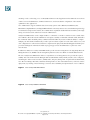
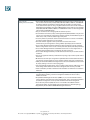
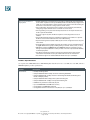
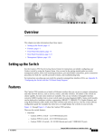
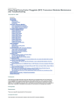
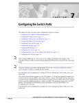
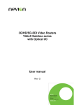
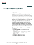
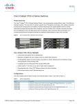
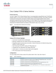
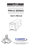
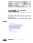
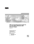
Data Sheet
Cisco Catalyst 2950
Long-Reach Ethernet Switches
Cisco’s Long Reach Ethernet switches meet the demands of high bandwidth
applications while leveraging existing copper wiring infrastructures. Catalyst® 2950
Long-Reach Ethernet (LRE) Series switches enable enterprise and service provider
customers to extend intelligent Ethernet services over existing phone and legacy
wiring, at distances of up to 5000 feet. Cisco is the only company with the breadth of
technologies that allow customers to deliver intelligent network services across any
combination of wired and wireless infrastructures.
The Cisco Catalyst 2950 LRE solution delivers cost-effective, high-performance broadband
access to enterprise campus environments and multi-tenant buildings (such as, hotels,
apartment buildings, and office buildings). The Cisco LRE technology dramatically extends
the reach of Ethernet up to 5,000 feet over existing Category 1/2/3 wiring at speeds from 2
to 15 Mbps symmetric. LRE co-exists on the same medium as Plain Old Telephone Service
(POTS), digital telephone, and ISDN traffic, and co-exists with asymmetric digital subscriber
line (ADSL) in the same wire bundle, allowing service providers to provision LRE to buildings
where broadband services already exist.
Enterprise
The Catalyst 2950 LRE enables enterprises to deploy productivity enhancing applications across
their entire network while avoiding the costs of rewiring. Based on Cisco’s market leading
Catalyst 2950 Series, the 2950 LRE is a familiar product for existing Cisco customers and allows
networks to reach areas previously not feasible due to wiring or distance limitations.
Metro Access
Ideal for metro Ethernet access in residential and small-office, home-office (SOHO) markets,
the Catalyst 2950 LRE switches extend intelligence to the metro access edge, enabling service
breadth, availability, security, and manageability while leveraging the existing in-building
wiring. Featuring advanced rate limiting, voice virtual LAN (VLAN) support, and multicast
management, these switches enable a variety of residential metro services such as Internet
access, voice over IP (VoIP), and broadcast video.
Hospitality
The Catalyst 2950 LRE broadband networking solution enables hoteliers to deliver secure
high-speed Internet access to guest and conference rooms to attract and retain business
travelers. By deploying the Cisco LRE solution, hotel owners can future proof their buildings
for a wide range of applications that will ensure operational efficiency and customer loyalty
for years to come while avoiding the costs of rewiring.
Cisco Systems, Inc.
All contents are Copyright © 2002 Cisco Systems, Inc. All rights reserved. Important Notices and Privacy Statement.
Page 1 of 19
Product Overview
The Cisco Catalyst® 2950 LRE switches are fixed-configuration, stackable models that provide wire-speed LRE and
Gigabit Ethernet connectivity for small and midsized networks. The Catalyst 2950 Series is an affordable product line
that brings intelligent services, such as enhanced security, high availability and advanced quality of service (QoS), to
the network edge—while maintaining the simplicity of traditional LAN switching. When a Catalyst 2950 LRE switch
is combined with a Catalyst 3550 Series switch, the solution can enable IP routing from the edge to the core of the
network. Embedded in Catalyst 2950 Series switches is the Cisco Cluster Management Suite (CMS) Software, which
allows users to simultaneously configure and troubleshoot multiple Catalyst desktop switches using a standard Web
browser. In addition to CMS, Cisco Catalyst 2950 LRE switches provide extensive management tools using Simple
Network Management Protocol (SNMP) network management platforms such as CiscoWorks for Switched
Internetworks.
The Cisco 2950 LRE solution includes the Cisco Catalyst® 2950 LRE switches, the Cisco 575 and 585 LRE Customer
Premise Equipment (CPE) devices, and the Cisco LRE POTS Splitter. Each LRE link is terminated with either the Cisco
575 or 585 LRE CPEs, and a POTS splitter is required when POTS traffic coexists with the LRE link over the same
line.
The Cisco Catalyst 2950 LRE switches consist of the following devices—which are based upon the Enhanced Image
(EI) Software for the Catalyst 2950 Series.
• Catalyst 2950ST-24-LRE—24 LRE ports + 2 10/100/1000BASE-T ports + 2 Small Form-Factor Pluggable (SFP)
ports (two of the four uplinks active at one time)
• Catalyst 2950ST-8-LRE—8 LRE ports + 2 10/100/1000BASE-T ports + 2 SFP ports (two of the four uplinks active
at one time)
The two built-in Gigabit Ethernet SFP ports support 1000BASE-SX and 1000BASE-LX modules. The dual SFP-based
and copper Gigabit Ethernet implementation provides customers with tremendous deployment flexibility—allowing
customers increased availability with the redundant uplinks. High levels of stack resiliency can also be implemented
by deploying dual redundant Gigabit Ethernet uplinks and UplinkFast technologies for high-speed uplink and stack
interconnection failover, and Per VLAN Spanning Tree Plus (PVST+) for uplink load balancing.
Long-Reach Ethernet Technology
The LRE technology employs Quadrature Amplitude Modulation (QAM). QAM modulation uses both signal
amplitude and phase to define each symbol. LRE uses the most sophisticated QAM technology with various
QAM modulations (QAM-256, QAM-128, QAM-64, QAM-32, QAM-16, QAM-8, and QAM-4). The system
administrator may choose profiles that use different modulations and frequency plans according to the line
specification and rate definition. LRE is designed to support multiQAM in order to achieve performance as close
to the physical limit as possible, while maintaining low cost and low power.
Cisco LRE facilitates the transport of symmetrical, bi-directional data over unshielded, copper twisted-pair telephone
wires originally intended for the frequency band between 300 Hz and 3.4 KHz. The system employs Frequency
Division Duplexing (FDD) to separate the downstream channel, the upstream channel, and POTS, ISDN, or PBX
signaling services in the frequency domain. This enables service providers to overlay LRE on existing POTS, ISDN,
or analog PBX signaling services without disruption. Both LRE and POTS/ISDN/analog PBX services may be
transmitted over the same line without interfering with each other.
Cisco Systems, Inc.
All contents are Copyright © 2002 Cisco Systems, Inc. All rights reserved. Important Notices and Privacy Statement.
Page 2 of 19
Intelligence in the Network
Networks of today are evolving to address four new developments at the network edge:
• Increase in desktop computing power
• Introduction of bandwidth-intensive applications
• Expansion of highly sensitive data on the network
• Presence of multiple device types, such as IP phones and wireless LAN access points
These new demands are contending for resources with many existing mission-critical applications. As a result, IT
professionals must view the edge of the network as critical to effectively manage the delivery of information and
applications.
As companies increasingly rely on networks as the strategic business infrastructure, it is more important than ever to
ensure their high availability, security, scalability and control. By adding Cisco intelligent functionality to the wiring
closet, customers can now deploy network-wide intelligent services that address these requirements in a consistent
way from the desktop to the core and through the WAN.
With Cisco Catalyst Intelligent Ethernet switches, Cisco enables companies to realize the full benefits of adding
intelligent services into their networks. Deploying capabilities that make the network infrastructure highly available to
accommodate time-critical needs, scalable to accommodate growth, secure enough to protect confidential information,
and capable of differentiating and controlling traffic flows are key to further optimizing network operations.
Network Security through Advanced Security Features
The Cisco Catalyst 2950 LRE Series switches offer enhanced data security through a wide range of security features.
These features allow customers to enhance LAN security with capabilities to secure network management traffic
through the protection of passwords and configuration information; to provide options for network security based
on users, ports and MAC addresses; and to enable more immediate reactions to intruder and hacker detection. The
security enhancements are available free-of-charge by downloading the latest software release for the Catalyst 3550
and 2950 switches.
Secure Shell (SSH) and Simple Network Management Protocol version 3 (SNMPv3) with encryption protect
information from being tampered with or eavesdropped by encrypting information being passed along the network,
thereby guarding administrative information. To use these features, the crypto (encrypted) Catalyst 2950 LRE
software image must be installed on your switch.
Private VLAN Edge isolates ports on a switch, ensuring that traffic travels directly from the entry point to the
aggregation device through a virtual path and cannot be directed to another port. Local Proxy Address Resolution
Protocol (ARP) works in conjunction with private VLAN edge to minimize broadcasts and maximize available
bandwidth.
Port-based Access Control Parameters (ACPs) restrict sensitive portions of the network by denying packets based
on source and destination MAC addresses, IP addresses, or TCP/UDP ports. ACP lookups are done in hardware;
therefore, forwarding performance is not compromised when implementing this type of security in the network. In
addition, Time-based ACLs allow configuration of differentiated services based on time periods. ACLs can also be
applied to filter traffic based on DSCP values. Port security provides another means to ensure the appropriate user
is on the network by limiting access based on MAC addresses. For authentication of users with a Terminal Access
Cisco Systems, Inc.
All contents are Copyright © 2002 Cisco Systems, Inc. All rights reserved. Important Notices and Privacy Statement.
Page 3 of 19
Controller Access Control System (TACACS+) or RADIUS server, 802.1x provides port-level security. SNMPv3
(non-crypto) monitors and controls network devices as well as manages configurations, performance, collection of
statistics and security.
With the multi-layer Cisco Catalyst 2950 LRE switches, network managers can implement high levels of console
security. Multilevel access security on the switch console and the web-based management interface prevents
unauthorized users from accessing or altering switch configuration TACACS+ or RADIUS authentication enables
centralized access control of the switch and restricts unauthorized users from altering the configuration. Deploying
security can be done through Cisco CMS Software Security Wizards, which ease the deployment of security features
that restrict user access to a server, a portion of the network, or access to the network.
Network Control through Advanced Quality of Service and Rate Limiting
The Catalyst 2950 LRE Series switches offer superior and highly granular QoS based on Layer 2-4 information, to
ensure that network traffic is classified, prioritized, and congestion is avoided in the best possible manner. The Catalyst
2950 LRE Series switches can classify, reclassify, police (determine if the packet is in or out of predetermined profiles
and affect actions on the packet), and mark or drop the incoming packets before the packet is placed in the shared
buffer. Packet classification allows the network elements to discriminate between various traffic flows and enforce
policies based on Layer 2 and Layer 3 QoS fields.
To implement QoS, these switches first identify traffic flows, or packet groups, and classify or reclassify these groups
using the DiffServ Code Point field (DSCP) in the IP packet and/or the 802.1p class of service (CoS) field in the
Ethernet packet. Classification and reclassification can also be based on criteria as specific as the source/destination
IP address, source/destination MAC address or the Layer 4 Transmission Control Protocol (TCP)/User Datagram
Protocol (UDP) ports. At the ingress (incoming port) level, the Catalyst switches will also perform policing and
marking of the packet.
After the packet goes through classification, policing, and marking, it is then assigned to the appropriate queue before
exiting the switch. The Catalyst 2950 LRE Series switches support four egress (outgoing port) queues per port, which
allows the network administrator to be more discriminating and specific in assigning priorities for the various
applications on the LAN. At the egress level, the switch performs scheduling, which is an algorithm/process that
determines the order in which the queues are processed. The switches support Weighted Round Robin (WRR)
scheduling or strict priority scheduling. The WRR scheduling algorithm ensures that the lower priority packets are
not entirely starved for bandwidth and are serviced without compromising the priority settings administered by the
network manager. Strict priority scheduling ensures that the highest priority packets will always get serviced first,
ahead of all other traffic, and that the other three queues will be serviced using WRR best effort.
These features allow network administrators to prioritize mission-critical and/or bandwidth-intensive traffic, such
as ERP (Oracle, SAP, and so on), voice (IP telephony traffic) and CAD/CAM over less time-sensitive applications
such as FTP or e-mail (SMTP). For example, it would be highly undesirable to have a large file download destined
to one port on a wiring closet switch and have quality implications such as increased latency in voice traffic, destined
to another port on this switch. This condition is avoided by ensuring that voice traffic is properly classified and
prioritized throughout the network. Other applications, such as web browsing, can be treated as low priority and
handled on a best-efforts basis.
Cisco Systems, Inc.
All contents are Copyright © 2002 Cisco Systems, Inc. All rights reserved. Important Notices and Privacy Statement.
Page 4 of 19
The Catalyst 2950 LRE Series switches are capable of allocating bandwidth based on several criteria including MAC
source address, MAC destination address, IP source address, IP destination address, and TCP/UDP port number.
Bandwidth allocation is essential in network environments requiring service-level agreements or when it is necessary
for the network manager to control the bandwidth given to certain users. The Catalyst 2950 LRE Series switches
support up to 6 policers per LRE port and up to 60 policers on a Gigabit Ethernet port. This gives the network
administrator very granular control of LAN bandwidth.
Network Availability
To provide efficient use of resources for bandwidth-hungry applications like multicasts, the Cisco Catalyst 2950 LRE
Series Intelligent switches support Internet Group Management Protocol (IGMP) snooping in hardware. Through the
support and configuration of IGMP snooping via the Cisco CMS Software, Catalyst 2950 LRE Series switches deliver
outstanding performance and ease of use in administering and managing multicast applications on the LAN.
The IGMP snooping feature allows the switch to “listen in” on the IGMP conversation between hosts and routers.
When a switch hears an IGMP join request from a host for a given multicast group, the switch adds the host’s port
number to the Group Destination Address (GDA) list for that group. And, when the switch hears an IGMP leave
request, it removes the host’s port from the Content Addressable Memory (CAM) table entry.
PVST+ allows users to implement redundant uplinks while also distributing traffic loads across multiple links. This is
not possible with standard Spanning-Tree Protocol implementations. Cisco UplinkFast technology ensures immediate
transfer to the secondary uplink, much better than the traditional 30 to 60 second convergence time. This is yet another
enhancement of the Spanning-Tree Protocol implementation. An additional feature that enhances performance is
Voice VLAN. This feature allows network administrators to assign voice traffic to a VLAN dedicated to IP
telephony—simplifying phone installations and providing easier network traffic administration and troubleshooting.
Multicast VLAN Registration (MVR) is designed for applications using wide-scale deployment of multicast traffic
across an Ethernet ring-based service provider network (for example, the broadcast of multiple television channels
over a service-provider network). MVR allows a subscriber on a port to subscribe and unsubscribe to a multicast
stream on the network-wide multicast VLAN.
Network Management
The Cisco Cluster Management Suite (CMS) is Web-based software that is embedded in Catalyst 3550, 2950, 2950
LRE, 3500 XL, 2900 XL, and 2900 LRE XL switches. Through Cisco Switch Clustering technology, users access
Cisco CMS with any standard Web browser to manage up to 16 of these switches at once, regardless of their
geographic proximity—with the option of using a single IP address for the entire cluster if desired. With the addition
of the Catalyst 3550 switches, Cisco CMS Software can now extend beyond routed boundaries for even more
flexibility in managing a Cisco cluster.
Cisco CMS provides an integrated management interface for delivering intelligent services, such as multi-layer
switching, QoS, multicast and security access control lists (ACLs). Thus, CMS allows administrators to take
advantage of benefits formerly reserved for only the most advance networks without having to learn the
command-line interface (CLI) or even the details of the technology.
The new Guide Mode in Cisco CMS leads the user step-by-step through the configuration of advanced features and
provides enhanced online help for context-sensitive assistance. In addition, Cisco AVVID (Architecture for Voice,
Video, and Integrated Data) Wizards provide automated configuration of the switch to optimally support video
Cisco Systems, Inc.
All contents are Copyright © 2002 Cisco Systems, Inc. All rights reserved. Important Notices and Privacy Statement.
Page 5 of 19
streaming or video conferencing, voice over IP (VoIP) and mission-critical applications. These Wizards can save hours
of time for network administrators, eliminate human errors, and ensure that the configuration of the switch is
optimized for these applications.
Cisco CMS Software supports standards-based connectivity options such as Ethernet, Fast Ethernet, Fast
EtherChannel, Gigabit Ethernet, and Gigabit EtherChannel connectivity. Because Cisco Switch Clustering technology
is not limited to a single stack of switches, Cisco CMS Software expands the traditional cluster domain beyond a single
wiring closet and saves time and effort for network administrators.
Catalyst 2950 LRE switches can be configured either as “command” or “member” switches in a Cisco switch cluster.
Cisco CMS also allows the network administrator to designate a standby or redundant command switch, which takes
the commander duties should the primary command switch fail. Other key features include the ability to configure
multiple ports and switches simultaneously, as well as perform software updates across the entire cluster at once, and
clone configurations to other clustered switches for rapid network deployments. Bandwidth graphs and link reports
provide useful diagnostic information and the topology map gives network administrators a quick view of the
network status.
In addition to CMS, Cisco Catalyst 2950 LRE switches provide extensive management tools using Simple Network
Management Protocol (SNMP) network management platforms such as CiscoWorks for Switched Internetworks.
The Cisco Catalyst 2950 LRE switches deliver a comprehensive set of management tools to provide the required
visibility and control in the network. Managed with CiscoWorks2000, Catalyst family switches can be configured
and managed to deliver end-to-end device, VLAN, traffic, and policy management. Coupled with CiscoWorks2000,
Cisco Resource Manager Essentials, a Web-based management tool, offers automated inventory collection, software
deployment, easy tracking of network changes, views into device availability, and quick isolation of error conditions.
Figure 1 Cisco Catalyst 2950 LRE Switches
Figure 2 Cisco Catalyst 2950ST 8 LRE Switch
Cisco Systems, Inc.
All contents are Copyright © 2002 Cisco Systems, Inc. All rights reserved. Important Notices and Privacy Statement.
Page 6 of 19
Figure 3 Cisco Catalyst 2950 Long-Reach Ethernet Solution
The Catalyst 2950 Series switches fully support the CISCO575-LRE and CISCO585-LRE CPEs and the Cisco LRE
POTS splitter. Please refer to the Cisco LRE CPE and Cisco LRE POTS Splitter data sheets for more information.
Cisco Systems, Inc.
All contents are Copyright © 2002 Cisco Systems, Inc. All rights reserved. Important Notices and Privacy Statement.
Page 7 of 19
Product Features and Benefits
Feature
Benefit
Performance
Robust Performance
Over Existing Telephone
Wiring
• 2-15 Mbps bandwidth over category 1/2/3/5 single-pair copper wiring over distances up
to 5,000 feet.
• Profiles available for optimizing upstream and downstream bandwidth requirements:
(Actual achievable data rates depend on cable quality, noise and cross talk
environment.)
Profile Name
Downstream
Upstream
Notes
LRE-15
15
15
LRE-15LL for low latency
LRE-15_5
15
5
LRE-15_3
15
3
LRE-15_1
15
1
LRE-10
10
10
LRE-10_5
10
5
LRE-10_3
10
3
LRE-10_1
10
1
LRE-8
8
8
LRE-7
7
7
LRE-5
5
5
LRE-4
4
4
LRE-4_1
4
1
LRE-3
3
3
LRE-2
2
2
LRE-998-15-4-M2
15
4
Plan 998 compliant w/ mask 2
LRE-997-10-4-M2
10
4
Plan 997 compliant w/ mask 2
LRE-10LL for low latency
LRE-5LL for low latency
LRE-4_1LL for low latency
• Rate selection automates the process of selecting a profile that is optimal on a given
interface thereby greatly improving the ease of installation and optimizing the
bandwidth for a given environment. Profiles are grouped into sequences that can be
configured by the customer.
• Flexibility to use either 10BaseT/100BaseTX/1000BaseT autosensing ports, or SFPs for
fiber connectivity to support LRE switch daisy-chaining, aggregation or server/router
connectivity.
• Full-duplex operation on all ports, delivering up to 15 Mbps symmetric on LRE ports
and up to 1000 Mbps symmetric on 10/100/1000 and SFP ports.
Cisco Systems, Inc.
All contents are Copyright © 2002 Cisco Systems, Inc. All rights reserved. Important Notices and Privacy Statement.
Page 8 of 19
Feature
Benefit
Robust Performance Over
Existing Telephone Wiring
continued
• Reed-Solomon Forward Error Correction and high interleaver protect data payload
and header information in noisy environments.
• LRE Link Persistence allows configuration of delay duration before dynamic MAC
addresses are removed from the MAC address table due to LRE link drops. Enabled by
default.
• Diagnostic Link Monitoring allows customers to track conditions on the LRE link and
take system-defined actions after certain thresholds are reached.
Availability
Superior Redundancy for
Fault Backup
• IEEE 802.1D Spanning-Tree Protocol support for redundant backbone connections and
loop-free networks simplifies network configuration and improves fault tolerance.
• Support for Cisco Spanning-Tree Protocol enhancements such as UplinkFast,
BackboneFast and PortFast technologies ensure quick fail-over recovery enhancing
overall network stability and availability.
• IEEE 802.1w Rapid Spanning-Tree Protocol (RSTP) provides rapid convergence of the
spanning tree independent of spanning-tree timers.
• Support for Cisco’s optional, 300-watt redundant AC power system provides a backup
power source for up to four units for improved fault tolerance and network uptime.
• Command switch redundancy enabled in the Cisco Cluster Management Suite (CMS)
Software allows customers to designate a backup command switch that takes over
cluster management functions if the primary command switch fails.
• Provides unidirectional link detection (UDLD) and Aggressive UDLD for detecting and
disabling unidirectional links on fiber-optic interfaces caused by incorrect fiber-optic
wiring or port faults.
Integrated Cisco IOS®
Features for Bandwidth
Optimization
• Bandwidth aggregation up to 4 Gbps (2 ports full duplex) through Gigabit
EtherChannel® technology and up to 240 Mbps (8 ports full duplex) through Port
Aggregation Protocol (PagP) technology on LRE ports enhances fault tolerance and
offers higher-speed aggregated bandwidth between switches, to routers and
individual servers.
• Per-port broadcast, multicast, and unicast storm control prevents faulty end stations
from degrading overall systems performance.
• Per virtual LAN (VLAN) Spanning Tree Plus (PVST+) allows for Layer 2 load sharing on
redundant links to efficiently utilize the extra capacity inherent in a redundant design.
• IEEE 802.1s Multiple Spanning-Tree Protocol (MSTP) allows a spanning tree instance
per VLAN enabling Layer 2 load sharing on redundant links.
• VLAN Trunking Protocol (VTP) pruning limits bandwidth consumption on VTP trunks
by flooding broadcast traffic only on trunk links required to reach the destination
devices. Dynamic Trunking Protocol (DTP) enables dynamic trunk configuration across
all ports in the switch.
• Internet Group Management Protocol (IGMP) snooping provides for fast client joins
and leaves of multicast streams and limits bandwidth-intensive video traffic to only
the requestors. Multicast VLAN Registration (MVR), IGMP filtering and fast-join and
immediate leave are available as enhancements.
• Multicast VLAN registration (MVR) continuously sends multicast streams in a
multicast VLAN while isolating the streams from subscriber VLANs for bandwidth and
security reasons.
• Supports additional frame formats: Ethernet II (tagged and untagged), 802.3 (SNAP
encapsulated tagged and untagged frames)
Cisco Systems, Inc.
All contents are Copyright © 2002 Cisco Systems, Inc. All rights reserved. Important Notices and Privacy Statement.
Page 9 of 19
Feature
Benefit
Security
Network-Wide Security
Features
• Filtering of incoming traffic flows based on Layer 2, Layer 3 or Layer 4 access control
parameters (ACPs) prevents unauthorized data flows.
– The following Layer 2 ACPs or a combination can be used for security classification
of incoming packets: source Media Access Control (MAC) address, destination MAC
address, and 16-bit Ethertype.
– The following Layer 3 and Layer 4 fields or a combination can be used for security
classification of incoming packets: source IP address, destination IP address, TCP
source or destination port number, User Datagram Protocol (UDP) source, or
destination port number. ACLs can also be applied to filter based on DSCP-values.
– Time-based ACLs allow configuration of differentiated services based on
time-periods.
• Secure Shell Protocol (SSH) provides secure login sessions and other
communications between two untrusted hosts over an insecure network by
encrypting the entire session. SSH features strong cryptographic authentication,
strong encryption, and integrity protection. To use this feature, the crypto (encrypted)
Catalyst 2950 LRE software image must be installed on your switch.
• SNMPv3 with encryption provides secure access to devices by authenticating and
encrypting all SNMP packets over the network. The encryption portion of SNMPv3
requires the crypto Catalyst 2950 LRE software image to be installed on your switch.
• Password recovery feature allows the administrator to protect access to the switch
configuration files by forcing a user with physical access to the switch to interrupt the
switch start process only by agreeing to set the system back to default configuration.
• SNMPv3 (non-crypto) monitors and controls network devices, manages
configurations, statistics collection, performance, and security
• Private VLAN edge (protected port) provides security and isolation between ports on a
switch, ensuring that voice traffic travels directly from its entry point to the
aggregation device through a virtual path and cannot be directed to a different port.
• Support for the 802.1x standard allows users to be authenticated regardless of which
LAN port they are accessing, and provides unique benefits to customers who have a
large base of mobile (wireless) users accessing the network.
• Port Security secures the access to a port based on the MAC address of a users device.
The aging feature removes the MAC address from the switch after a specific timeframe
to allow another device to connect to the same port.
• MAC Address Notification allows administrators to be notified of new users added or
removed from the network.
• Spanning-tree root guard (STRG) prevents edge devices not in the network
administrator's control from becoming Spanning-Tree Protocol root nodes.
• The Spanning-Tree Protocol PortFast/bridge protocol data unit (BPDU) guard feature
disables access ports with Spanning-Tree Protocol PortFast-enabled upon reception of
a BPDU, and increases network reliability, manageability, and security.
• Multilevel security on console access prevents unauthorized users from altering the
switch configuration.
• TACACS+ and RADIUS authentication to enable centralized control of the switch and
restrict unauthorized users from altering the configuration.
• The user-selectable address-learning mode simplifies configuration and enhances
security.
• Trusted Boundary provides the ability to trust the QoS priority settings if an IP phone
is present and disable the trust setting in the event that the IP phone is removed,
thereby preventing a rogue user from overriding prioritization policies in the network.
Cisco Systems, Inc.
All contents are Copyright © 2002 Cisco Systems, Inc. All rights reserved. Important Notices and Privacy Statement.
Page 10 of 19
Feature
Benefit
Network-Wide Security
Features
continued
• IGMP Filtering provides multicast authentication by filtering out non-subscribers and
limits the number of concurrent multicast streams available per port.
• Support for dynamic VLAN assignment through implementation of VLAN Membership
Policy Server (VMPS) client functionality provides flexibility in assigning ports to
VLANs. Dynamic VLAN enables fast assignment of IP address.
• Cisco CMS Software Security Wizards ease the deployment of security features for
restricting user access to a server, a portion of the network or access to the network.
Quality of Service (QoS)
Overview
• The switches support the aggregate QoS model by enabling classification, policing/
metering, and marking functions on a per-port basis at ingress and queuing/
scheduling function at egress.
• The switches support configuring QoS ACPs on all ports to ensure proper policing and
marking on a per-packet basis using ACPs. Up to four ACPs per switch are supported in
configuring either QoS ACPs or security filters.
QoS Classification Support at Ingress
• The switches support QoS classification of incoming packets for QoS flows based on
Layer 2, Layer 3, and Layer 4 fields.
• The following Layer 2 fields or a combination can be used for classifying incoming
packets to define QoS flows: source MAC address, destination MAC address, 16-bit
Ethertype.
The switches support identification of traffic based on Layer 3 ToS field – DSCP values.
• The following Layer 3 and 4 fields or a combination can be used to classify incoming
packets to define QoS flows: source IP address, destination IP address, TCP source or
destination port number, UDP source or destination port number.
QoS Metering/Policing at Ingress
• Support for metering/policing of incoming packets restricts incoming traffic flows to a
certain rate.
• The switches support up to 6 policers per LRE port, and 60 policers on a Gigabit
Ethernet port.
• The switches offer granularity of traffic flows at 1 Mbps on LRE ports, and 8 Mbps on
Gigabit Ethernet ports.
QoS Marking at Ingress
• The switches support marking/re-marking packets based on state of policers/meters.
• The switches support marking/re-marking based on the following mappings: from
DiffServ Code Point (DSCP) to 802.1p, and 802.1p to DSCP.
• The switches support 14 well-known and widely used DSCP values.
• The switches support classifying or reclassifying packets based on default DSCP per
port. Also support classification based on DSCP-values in ACL.
• The switches support classifying or reclassifying frames based on default 802.1p value
per port.
• The switches support 802.1p override at ingress.
QoS Scheduling Support at Egress
• Four queues per egress port are supported in hardware.
• The Weighted Round Robin (WRR) queuing algorithm ensures that low-priority queues
are not starved.
• Strict-priority queue configuration via Strict Priority Scheduling ensures that
time-sensitive applications such as voice always follow an expedited path through the
switch fabric.
Cisco Systems, Inc.
All contents are Copyright © 2002 Cisco Systems, Inc. All rights reserved. Important Notices and Privacy Statement.
Page 11 of 19
Feature
Benefit
Sophisticated Traffic Management
• The switch supports up to 6 policers per LRE port and up to 60 policers on a Gigabit
Ethernet port.
• The switches offer granularity of traffic flows at 1 Mbps on LRE ports, and 8 Mbps on
Gigabit Ethernet ports.
• The switch offers the ability to limit data flows based on MAC source/destination
address, IP source/destination address, TCP/UDP port numbers, or any combination of
these fields.
• The switch offers the ability to manage data flows asynchronously upstream and
downstream from the end station or on the uplink.
Management
Superior Manageability
• An embedded Remote Monitoring (RMON) software agent supports four RMON
groups (history, statistics, alarms, and events) for enhanced traffic management,
monitoring, and analysis.
• The switch supports all nine RMON groups through the use of a Cisco SwitchProbe®
Analyzer (Switched Port Analyzer [SPAN]) port, permitting traffic monitoring of a single
port, a group of ports, or the entire switch from a single network analyzer or RMON
probe.
• A SPAN port monitors traffic of a single port from a single network analyzer or RMON
probe.
• Remote Switch Port Analyzer (RSPAN) allows network administrators to locally
monitor ports in a Layer 2 switch network from any other switch in the same network.
• The Domain Name System (DNS) provides IP address resolution with user-defined
device names.
• Network Timing Protocol (NTP) provides an accurate and consistent timestamp to all
switches within the intranet.
• Trivial File Transfer Protocol (TFTP) reduces the cost of administering software
upgrades by downloading from a centralized location.
• Crash Information support enables switch to generate a crash file for improved
troubleshooting.
• RTTMON-MIB allows users to monitor network performance between a Catalyst
switch and a remote device.
• Multifunction LEDs per port for port status, 10BASE-T/100BASE-TX/1000BASE-T
indication, as well as switch-level status LEDs for system and redundant power supply
provide a comprehensive and convenient visual management system.
• Read-only MIB support for LRE profiles and FastEthernet ports on LRE CPEs
Cisco Systems, Inc.
All contents are Copyright © 2002 Cisco Systems, Inc. All rights reserved. Important Notices and Privacy Statement.
Page 12 of 19
Feature
Benefit
Cisco Cluster
Management Suite (CMS)
• Cisco Cluster Management Suite (CMS) Software allows the user to manage up to 16
inter-connected Cisco Catalyst 3550, 2950, 2950 LRE, 3500 XL, 2900 XL, and 2900 LRE
XL switches without the limitation of being physically located in the same wiring
closet, and with the option of using a single IP address for the entire cluster if desired.
Full backward compatibility of the Cisco CMS Software ensures that any Cisco Catalyst
3550, 2950, 2950 LRE, 3500 XL, 2900 XL, and 2900 LRE XL switch can be managed with
a Cisco Catalyst 2950 LRE Switch.
• Easy to use interface for managing LRE rate selection process.
• Cisco Architecture for Voice, Video, and Integrated Data (AVVID) Wizards use just a few
user inputs to automatically configure the switch to optimally handle different types of
traffic: voice, video, multicast, and/or high-priority data.
• A security wizard is provided to restrict unauthorized access to servers and networks,
and restrict certain applications on the network.
• One-click software upgrades can be performed across the entire cluster
simultaneously, and configuration cloning enables rapid deployment of networks.
• Cisco Cluster Management Suite Software has been extended to include multilayer
feature configurations such as access control parameters (ACPs) and QoS parameters.
• Cisco Cluster Management Suite Guide Mode assists users in the configuration of
powerful advanced features by providing step-by-step instructions.
• Cisco Cluster Management Suite provides enhanced online help for context-sensitive
assistance.
• Easy-to-use graphical interface provides both a topology map and front panel view of
the cluster.
• Multi-device and multi-port configuration capabilities allow network administrators to
save time by configuring features across multiple switches and ports simultaneously.
• Ability to launch the web-based management for a Cisco Aironet Wireless Access Point
by simply clicking on its icon in the topology map.
• User-personalized interface allows users to modify polling intervals, table views, and
other settings within CMS and retain these settings the next time they use CMS.
• Alarm notification provides automated email notification of network errors and alarm
thresholds
Support for CiscoWorks
• Manageable through CiscoWorks network management software on a per-port and
per-switch basis providing a common management interface for Cisco routers,
switches and hubs.
• Simple Network Management Protocol (SNMP) v1, v2, and v3 and Telnet interface
support delivers comprehensive in-band management, and a command-line interface
(CLI)-based management console provides detailed out-of-band management
• Cisco Discovery Protocol (CDP) Versions 1 and 2 enable a CiscoWorks network
management station to automatically discover the switch in a network topology.
• Supported by the CiscoWorks 2000 LAN Management Solution
Cisco Systems, Inc.
All contents are Copyright © 2002 Cisco Systems, Inc. All rights reserved. Important Notices and Privacy Statement.
Page 13 of 19
Feature
Benefit
Ease of Use and Ease of
Deployment
• Archive download is a convenient tool to upgrade (or downgrade) the set of binaries
on the switch. It performs memory availability checks and automatically configures the
switch to use the new binaries. Archive upload can be used to archive the existing set
of binaries on the switch to a storage (such as a TFTP server).
• Auto-configuration eases deployment of switches in the network by automatically
configuring multiple switches across a network via a boot server.
• Auto-negotiating on all ports automatically selects half- or full-duplex transmission
mode to optimize bandwidth.
• Cisco VTP supports dynamic VLANs and dynamic trunk configuration across all
switches.
• Voice VLAN simplifies telephony installations by keeping voice traffic on a separate
VLAN for easier network administration and troubleshooting.
• Dynamic Trunking Protocol (DTP) enables dynamic trunk configuration across all ports
in the switch.
• Port Aggregation Protocol (PAgP) automates the creation of Cisco Fast EtherChannel®
or Gigabit EtherChannel groups, enabling linking to another switch, router, or server.
• IEEE 802.3z-compliant 1000BASE-SX and 1000BASE-LX physical interface support
through a field-replaceable SFP module provides customers unprecedented flexibility
in switch deployment.
• The default configuration stored in Flash ensures that the switch can be quickly
connected to the network and can pass traffic with minimal user intervention.
• The switches support non-standard Ethernet frame sizes up to 1,536 bytes.
Product Specifications
(See separate Cisco LRE CPE and Cisco LRE POTS Splitter data sheets for Cisco 575 CPE, Cisco 585 CPE, and Cisco
LRE POTS Splitter product specifications.)
Feature
Description
Performance
• 8.8-Gbps switching fabric
• Catalyst 2950ST-24-LRE: 4.7-Gbps maximum forwarding bandwidth
• Catalyst 2950ST-8-LRE: 4.2-Gbps maximum forwarding bandwidth (Forwarding rates
based on 64-byte packets)
• Catalyst 2950ST-24-LRE: 3.5-Mpps wire-speed forwarding rate
• Catalyst 2950ST-8-LRE: 3.2-Mpps wire-speed forwarding rate
• 8-MB memory architecture shared by all ports
• Up to 32-MB SDRAM and 8-MB Flash memory
• Configurable up to 8000 MAC addresses
• Configurable maximum transmission unit (MTU) of up to 1,536 bytes
Cisco Systems, Inc.
All contents are Copyright © 2002 Cisco Systems, Inc. All rights reserved. Important Notices and Privacy Statement.
Page 14 of 19
Feature
Description
Management
Catalyst 2950 LRE specific:
• ETHER-LIKE-MIB
• CISCO-VDSL-LINE-MIB
• IF-MIB (RFC 1573) support for CPE Ethernet ports
• RMON-MIB (RFC 1757) support for CPE Ethernet ports
Catalyst 2950 Series:
• BRIDGE-MIB
• CISCO-2900-MIB
• CISCO-CDP-MIB
• CISCO-CLUSTER-MIB
• CISCO-CONFIG-MAN-MIB
• CISCO-FLASH-MIB
• CISCO-IMAGE-MIB
• CISCO-MAC-NOTIFICATION-MIB
• CISCO-MEMORY-POOL-MIB
• CISCO-PAGP-MIB
• CISCO-PING-MIB
• CISCO-PROCESS-MIB
• CISCO-PRODUCTS-MIB
• CISCO-RTTMON-MIB
• CISCO-SMI
• CISCO-STACKMAKER-MIB
• CISCO-STP-EXTENSIONS-MIB
• CISCO-SYSLOG-MIB
• CISCO-TC
• CISCO-TCP-MIB
• CISCO-VLAN-MEMBERSHIP-MIB
• CISCO-VTP-MIB
• ENTITY-MIB
• IANAifType-MIB
• IF-MIB (RFC 1573)
• OLD-CISCO-CHASSIS-MIB
• OLD-CISCO-CPU-MIB
• OLD-CISCO-INTERFACES-MIB
• OLD-CISCO-IP-MIB
• OLD-CISCO-MEMORY-MIB
• OLD-CISCO-SYSTEM-MIB
• OLD-CISCO-TCP-MIB
• OLD-CISCO-TS-MIB
• RFC1213-MIB (MIB-II)
• RFC1398-MIB (ETHERNET-MIB)
• RMON-MIB (RFC 1757)
• RS-232-MIB
• SNMPv2-MIB
• SNMPv2-SMI
• SNMPv2-TC
• TCP-MIB
• UDP-MIB
Cisco Systems, Inc.
All contents are Copyright © 2002 Cisco Systems, Inc. All rights reserved. Important Notices and Privacy Statement.
Page 15 of 19
Feature
Description
Standards
•
•
•
•
•
•
•
•
•
•
•
•
•
•
•
Y2K
• Y2K compliant
Connectors and
Cabling
• LRE ports: RJ-21 connector; one-pair Category 1, 2, or 3 unshielded twisted-pair (UTP)
cabling
• 10BASE-T ports: RJ-45 connectors; two-pair Category 3, 4, or 5 unshielded twisted-pair
(UTP) cabling
• 100BASE-TX ports: RJ-45 connectors; two-pair Category 5 UTP cabling
• 1000BASE-T ports: RJ-45 connectors; two-pair Category 5 UTP cabling
• 1000BASE-SX and -LX SFP-based ports: SC fiber connectors, single-mode or multimode
fiber
• Management console port: 8-pin RJ-45 connector, RJ-45-to-RJ-45 rollover cable with
RJ-45-to-DB9 adapter for PC connections; for terminal connections, use RJ-45-to-DB25
female data-terminal-equipment (DTE) adapter (can be ordered separately from Cisco, part
number ACS-DSBUASYN=)
Power Connectors
Customers can provide power to a switch by using either the internal power supply or the
Cisco Redundant Power System (RPS) 300. The internal power supply connector is located in
the front of the switch and the RPS connector is located at the back of the switch.
Internal Power Supply Connector
• The internal power supply is an auto-ranging unit.
• The internal power supply supports input voltages between 100 and 240 VAC.
• Use the supplied AC power cord to connect the AC power connector to an AC power outlet.
Cisco RPS Connector
• The connector offers connection for an optional Cisco RPS 300 that uses AC input and
supplies DC output to the switch.
• The connector offers a 300-watt redundant power system that can support six external
network devices and provides power to one failed device at a time.
• The connector automatically senses when the internal power supply of a connected device
fails and provides power to the failed device, preventing loss of network traffic.
• Attach only the Cisco RPS 300 (model PWR300-AC-RPS-N1) to the
redundant-power-supply receptacle.
Indicators
• Per-port status LEDs: link integrity, disabled, activity, and speed (uplinks only) indications.
• System status LEDs: system and RPS indications.
IEEE 802.1x
IEEE 802.1w
IEEE 802.1s
IEEE 802.3x full duplex on 10BASE-T, 100BASE-TX, and 1000BASE-T ports
IEEE 802.1D Spanning-Tree Protocol
IEEE 802.1p class-of-service (CoS) prioritization
IEEE 802.1Q VLAN
IEEE 802.3 10BASE-T specification
IEEE 802.3u 100BASE-TX specification
IEEE 802.3ab 1000BASE-T specification
IEEE 802.3z 1000BASE-X specification
1000BASE-SX (SFP)
1000BASE-LX (SFP)
RMON I and II standards
SNMPv1, SNMPv2c, SNMPv3
Cisco Systems, Inc.
All contents are Copyright © 2002 Cisco Systems, Inc. All rights reserved. Important Notices and Privacy Statement.
Page 16 of 19
Feature
Description
Dimensions and
Weight (H x W x D)
• 1.72 x 17.5 x 9.7 in. (4.36 x 44.5 x 24.6 cm) (Catalyst 2950ST-24-LRE, 2950ST-8-LRE)
• 1.0 rack-unit high
• 8.5 lb (3.9 kg) (Catalyst 2950ST-24-LRE, 2950ST-8-LRE)
Environmental
Ranges
•
•
•
•
•
•
Power Requirements
• Catalyst 2950ST-24-LRE: Power consumption: 45W maximum, 154 BTUs per hour
• Catalyst 2950ST-8-LRE: Power consumption: 30W maximum, 102 BTUs per hour
• AC input voltage/frequency: 100 to 127/200 to 240 VAC (auto-ranging), 50 to 60 Hz
Mean Time Between
Failure
(MTBF)–Predicted
• Catalyst 2950ST-24-LRE: 324,854 hours
• Catalyst 2950ST-8-LRE: 420,254 hours
Operating temperature: 32° to 113°F (0° to 45°C)
Storage temperature: –13° to 158°F (–25° to 70°C)
Operating relative humidity: 10 to 85% (non-condensing)
Operating altitude: Up to 10,000 ft (3,000 m)
Storage altitude: Up to 15,000 ft (4,570 m)
Not intended for use on top of desktops or in open office environments
Regulatory Agency Approvals
Safety Certifications
•
•
•
•
•
UL mark to UL60950
CUL mark to CAN/CSA C22.2 No. 60950-00
TUV GS mark to EN60950
Evaluated to AS/NZ 3260 and TS001
CE mark
Electromagnetic
Compatibility
Certifications
•
•
•
•
•
•
•
•
•
•
FCC Part 15 Class A
EN 55022: 1998 Class A (CISPR22 Class A)
EN 55024: 1998 (CISPR24)
VCCI Class A
AS/NZS 3548 Class A
CE Marking
CNS 13438
BSMI Class A
MIC
BCIQ
Warranty
• Limited lifetime warranty
Cisco Systems, Inc.
All contents are Copyright © 2002 Cisco Systems, Inc. All rights reserved. Important Notices and Privacy Statement.
Page 17 of 19
Service and Support
The services and support programs described in the table below are available as part of the Cisco Desktop Switching
Service and Support solution, and are available directly from Cisco and through resellers.
Service and Support
Features
Benefits
•
•
•
•
•
•
• Supplements existing staff
• Ensures functionality meets needs
• Mitigates risk
Advanced Services
Total Implementation
Solutions (TIS) available
direct from Cisco
Packaged Total
Implementation
Solutions (Packaged TIS)
available through
resellers
Project management
Site survey, configuration deployment
Installation, text, and cutover
Training
Major Moves, Adds, Changes (MAC)
Design review and product staging
Technical Support Services
SMARTnet and
SMARTnet Onsite (OS)
available direct from
Cisco
Packaged SMARTnet
available through
resellers
• 24x7 access to software updates
• Web access to technical repositories
• Telephone support through the Technical
Assistance Center
• Advance replacement of hardware parts
• Enables proactive or expedited issue
resolution
• Lowers cost of ownership by utilizing
Cisco expertise and knowledge
• Minimize network downtime
Ordering Information
Model Numbers
Configuration
WS-C2950ST-24-LRE
• 24 LRE ports + 2 10/100/1000BASE-T ports + 2 SFP ports (two of the four uplinks active
at one time)
• Based upon the 2950 Enhanced Software Image (EI)
WS-C2950ST-8-LRE
• 8 LRE ports + 2 10/100/1000BASE-T ports + 2 SFP ports (two of the four uplinks active at
one time)
• Based upon the 2950 Enhanced Software Image (EI)
GLC-SX-MM(=)
• GE SFP, LC connector SX transceiver
GLC-LH-SM(=)
• GE SFP, LC connector LX transceiver
For More Information on Cisco Products, Contact:
• US and Canada: 800 553-NETS (6387)
• Europe: 32 2 778 4242
• Australia: 612 9935 4107
• Other: 408 526-7209
• World Wide Web URL: http://www.cisco.com
Cisco Systems, Inc.
All contents are Copyright © 2002 Cisco Systems, Inc. All rights reserved. Important Notices and Privacy Statement.
Page 18 of 19
Corporate Headquarters
Cisco Systems, Inc.
170 West Tasman Drive
San Jose, CA 95134-1706
USA
www.cisco.com
Tel: 408 526-4000
800 553-NETS (6387)
Fax: 408 526-4100
European Headquarters
Cisco Systems International BV
Haarlerbergpark
Haarlerbergweg 13-19
1101 CH Amsterdam
The Netherlands
www-europe.cisco.com
Tel: 31 0 20 357 1000
Fax: 31 0 20 357 1100
Americas Headquarters
Cisco Systems, Inc.
170 West Tasman Drive
San Jose, CA 95134-1706
USA
www.cisco.com
Tel: 408 526-7660
Fax: 408 527-0883
Asia Pacific Headquarters
Cisco Systems, Inc.
Capital Tower
168 Robinson Road
#22-01 to #29-01
Singapore 068912
www.cisco.com
Tel: +65 6317 7777
Fax: +65 6317 7799
Cisco Systems has more than 200 offices in the following countries and regions. Addresses, phone numbers, and fax numbers are listed on the
Cisco Web site at www.cisco.com/go/offices
Argentina • Australia • Austria • Belgium • Brazil • Bulgaria • Canada • Chile • China PRC • Colombia • Costa Rica • Croatia
Czech Republic • Denmark • Dubai, UAE • Finland • France • Germany • Greece • Hong Kong SAR • Hungary • India • Indonesia • Ireland
Israel • Italy • Japan • Korea • Luxembourg • Malaysia • Mexico • The Netherlands • New Zealand • Norway • Peru • Philippines • Poland
Portugal • Puerto Rico • Romania • Russia • Saudi Arabia • Scotland • Singapore • Slovakia • Slovenia • South Africa • Spain • Sweden
S w i t z e r l a n d • Ta i w a n • T h a i l a n d • Tu r k e y • U k r a i n e • U n i t e d K i n g d o m • U n i t e d S t a t e s • Ve n e z u e l a • Vi e t n a m • Z i m b a b w e
All contents are Copyright © 1992–2002, Cisco Systems, Inc. All rights reserved. Catalyst, Cisco, Cisco IOS, Cisco Systems, the Cisco Systems logo, EtherChannel, EtherSwitch, and GigaStack are registered trademarks of
Cisco Systems, Inc. and/or its affiliates in the U.S. and certain other countries.
All other trademarks mentioned in this document or Web site are the property of their respective owners. The use of the word partner does not imply a partnership relationship between Cisco and any other company.
(0208R)
10/02 BW8623