1
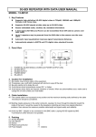
3G/HD/SD-SDI Video Routers VikinX Sublime series with Optical I/O User manual Rev. G Nevion Nordre Kullerød 1 3241 Sandefjord Norway Tel: +47 33 48 99 99 nevion.com VikinX Sublime Optical Routers Rev. G Nevion Support Nevion Europe Nevion USA P.O. Box 1020 3204 Sandefjord, Norway Support phone 1: +47 33 48 99 97 Support phone 2: +47 90 60 99 99 1600 Emerson Avenue Oxnard, CA 93033, USA Toll free North America: (866) 515-0811 Outside North America: +1 (805) 247-8560 E-mail: [email protected] See http://www.nevion.com/support/ for service hours for customer support globally. Revision history Current revision of this document is the uppermost in the table below. Rev. G F 5 Repl. F 5 4 Date 2014-01-03 2013-07-18 2012-02-20 Sign AJM JGS AAA 4 3 3 2 2011-08-22 2011-07-14 NBS NBS 2 1 1 0 2011-03-29 2011-03-25 NBS NBS 0 - 2011-01-25 NBS Change description Removed optical specification Updated chapter 5.2 with supported network modes Added comment for the MRP protocol option in Chapter 3.6. Fan error alarm described in Chapter 4.2 and Appendix B.1 and B.2. Added Chapter 8. Updated Chapter 7.1.2 Added Appendix B. Added Grass Valley Native Protocol in Chapter 3.6 and Appendix B.2. Updated Chapter 7. Updated Chapter 3.6. Added information on Nevion branded SFP’s. Corrected housing and gender spec on D-sub 9-pin contacts. Added SD-SDI Cable EQ spec in Chapter 2.4. Changed Chapter 3.8. Added Declaration of Conformity. First release. nevion.com | 2 VikinX Sublime Optical Routers Rev. G Contents Revision history ........................................................................................................ 2 1 Product overview ................................................................................................... 5 1.1 Product versions ........................................................................................................... 5 2 Specifications ........................................................................................................ 7 2.1 Mechanics ..................................................................................................................... 7 2.1.1 Weight and power consumption ................................................................................. 7 2.2 Power Supply ................................................................................................................ 7 2.3 Control .......................................................................................................................... 8 2.4 3G/HD -SDI specifications ............................................................................................. 8 2.5 Connection details......................................................................................................... 9 2.5.1 16x16 and 32x32 versions.......................................................................................... 9 2.5.2 64x64 versions ..........................................................................................................10 3 Configuration ....................................................................................................... 12 3.1 Router level ..................................................................................................................12 3.2 Router mode ................................................................................................................12 3.3 Power alarm .................................................................................................................17 3.4 Power-up mode ............................................................................................................17 3.5 Configuring switching time ...........................................................................................17 3.6 Configuring protocol options .........................................................................................17 3.7 Configuring Input options .............................................................................................19 3.7.1 Input EQ ....................................................................................................................19 3.8 Configuring Output options ...........................................................................................20 3.8.1 Output reclocker ........................................................................................................20 3.8.2 Slew rate settings ......................................................................................................20 3.8.3 Laser settings ............................................................................................................21 4 LED status indication ........................................................................................... 22 4.1 Start-up ........................................................................................................................22 4.2 Alarm states .................................................................................................................22 4.3 Ethernet states .............................................................................................................22 4.4 SL-PWR-300 LEDs ......................................................................................................23 5 Router communication......................................................................................... 24 5.1 Serial connection..........................................................................................................24 5.1.1 Maximum cable length (RS-232) ...............................................................................24 5.2 Ethernet connection .....................................................................................................25 5.2.1 HW limitations ...........................................................................................................25 5.3 NCB connection ...........................................................................................................26 5.3.1 Connecting control panels .........................................................................................26 5.3.2 Pin-out and cable type ...............................................................................................26 5.3.3 Termination plug .......................................................................................................27 5.3.4 Control bus structure .................................................................................................27 5.3.5 Maximum distance between NCB devices .................................................................27 6 Connecting video signals to the router ................................................................ 28 6.1 Optical interface ...........................................................................................................28 6.2 Electrical interface ........................................................................................................28 7 Control Panel operation ....................................................................................... 29 7.1 Button description ........................................................................................................29 nevion.com | 3 VikinX Sublime Optical Routers Rev. G 7.1.1 A/V Toggle ................................................................................................................29 7.1.2 Panel Enable .............................................................................................................29 7.1.3 Take on/off ................................................................................................................29 7.1.4 Take ..........................................................................................................................29 7.1.5 Output .......................................................................................................................29 7.1.6 Input ..........................................................................................................................30 7.1.7 XY .............................................................................................................................30 7.1.8 Salvo .........................................................................................................................30 7.1.9 Lock ..........................................................................................................................30 7.1.10 Protect.....................................................................................................................30 8 Fan monitoring and replacement ......................................................................... 31 General environmental requirements for Nevion equipment .................................. 32 Product Warranty.................................................................................................... 33 Important notes regarding Software in the VikinX Sublime router family range ...... 34 Appendix A Materials declaration and recycling information .................................. 35 A.1 Materials declaration ....................................................................................................35 A.2 Recycling information...................................................................................................35 Appendix B Additional Protocol information ............................................................ 36 B.1 Leitch Pass-Through protocol ......................................................................................36 B.2 Grass Valley Native protocol ........................................................................................36 nevion.com | 4 VikinX Sublime Optical Routers Rev. G 1 Product overview This User Manual presents the features, installation and operation procedures of the 3G/HD/SD-SDI routers of the Sublime range with optical I/O. Router sizes range from 16x16 to 128x1281 Hot pluggable optics Software based Configurator for easy system set-up TCP/IP, RS-232 and NCB Control (RJ-45) Programmable multi- single- and dual bus control panels Ultra Slim frame depth Low Power, high reliability design Redundant power supply system with front indicators Interoperability with existing VikinX routers Future proof and flexible product range 1.1 Product versions The following versions of the VikinX Sublime 3G/HD/SD-SDI Routers with optical I/O are available: 3G/HD/SD-SDI – 19” - 1RU, depth 10cm: SL-3GHD1616-16OPT / SL-3GHD1616 –CP-16OPT 16x16 HD-SDI Router (Multirate, 270Mbps-2.970Gbps). Specs as for SL-3GHD1616, but with 16 Optical I/O. Programmable X-Y control panel (on CP version). 3G/HD/SD-SDI – 19” - 2RU, depth 10cm: SL-3GHD3232-16OPT / SL-3GHD3232 –CP-16OPT SL-3GHD3232-32OPT / SL-3GHD3232 –CP-32OPT 32x32 HD-SDI Router (Multirate, 270Mbps-2.970Gbps). Specs as for SL-3GHD3232, but with 16 Optical I/O and 16 Electrical I/O. Programmable X-Y control panel (on CP version). 32x32 HD-SDI Router (Multirate, 270Mbps-2.970Gbps). Specs as for SL-3GHD3232, but with 32 Optical I/O. Programmable X-Y control panel (on CP version). 3G/HD/SD-SDI – 19” - 4RU, depth 10cm: SL-3GHD6464-16OPT / SL-3GHD6464 –CP-16OPT SL-3GHD6464-32OPT / SL-3GHD6464 –CP-32OPT SL-3GHD6464-48OPT / SL-3GHD6464 –CP-48OPT 64x64 HD-SDI Router (Multirate, 270Mbps-2.970Gbps). Specs as for SL-3GHD6464, but with 16 Optical I/O and 48 Electrical I/O. Programmable X-Y control panel (on CP version). 64x64 HD-SDI Router (Multirate, 270Mbps-2.970Gbps). Specs as for SL-3GHD6464, but with 32 Optical I/O and 32 Electrical I/O. Programmable X-Y control panel (on CP version). 64x64 HD-SDI Router (Multirate, 270Mbps-2.970Gbps). Specs as for SL-3GHD6464, but with 48 Optical I/O and 16 Electrical I/O. Programmable X-Y control panel (on CP version). 1 The 8RU Sublime variants are described further in a separate User Manual. This User Manual covers all 1RU, 2RU and 4RU versions (up to SL-3GHD6464-64OPT). nevion.com | 5 VikinX Sublime Optical Routers SL-3GHD6464-64OPT / SL-3GHD6464 –CP-64OPT Rev. G 64x64 HD-SDI Router (Multirate, 270Mbps-2.970Gbps). Specs as for SL-3GHD6464, but with 64 Optical I/O. Programmable X-Y control panel (on CP version). 3G/HD/SD-SDI – 19” - 8RU, depth 10cm2: SL-3GHD128128-16OPT SL-3GHD128128-32OPT SL-3GHD128128-48OPT SL-3GHD128128-64OPT SL-3GHD128128-80OPT SL-3GHD128128-96OPT SL-3GHD128128112OPT SL-3GHD128128128OPT 128x128 HD-SDI Router (Multirate, 270Mbps-2.970Gbps). Specs as for SL-3GHD128128, but with 16 Optical I/O and 112 Electrical I/O. 128x128 HD-SDI Router (Multirate, 270Mbps-2.970Gbps). Specs as for SL-3GHD128128, but with 32 Optical I/O and 96 Electrical I/O. 128x128 HD-SDI Router (Multirate, 270Mbps-2.970Gbps). Specs as for SL-3GHD128128, but with 48 Optical I/O and 80 Electrical I/O. 128x128 HD-SDI Router (Multirate, 270Mbps-2.970Gbps). Specs as for SL-3GHD128128, but with 64 Optical I/O and 64 Electrical I/O. 128x128 HD-SDI Router (Multirate, 270Mbps-2.970Gbps). Specs as for SL-3GHD128128, but with 80 Optical I/O and 48 Electrical I/O. 128x128 HD-SDI Router (Multirate, 270Mbps-2.970Gbps). Specs as for SL-3GHD128128, but with 96 Optical I/O and 32 Electrical I/O. 128x128 HD-SDI Router (Multirate, 270Mbps-2.970Gbps). Specs as for SL-3GHD128128, but with 112 Optical I/O and 16 Electrical I/O. 128x128 HD-SDI Router (Multirate, 270Mbps-2.970Gbps). Specs as for SL-3GHD128128, but with 128 Optical I/O. Available Control Panels – 19” – 1RU: SL-16XY-CP SL-8XY-CP SL-16D-CP SL-32S-CP SL-32S-CP-GPI SL-16S-CP SL-16S-CP-GPI SL-8S-CP SL-8S-CP-GPI SL-16XY-CP Multi bus X-Y 16x16 panel. Multi bus X-Y 8x8 panel. Dual bus 16x2 panel. Single bus 32x1 panel. Single bus 32x1 panel with GPI / Joystick / Tally interface. Single bus 16x1 panel. Single bus 16x1 panel with GPI / Joystick / Tally interface. Single bus 8x1 panel. Single bus 8x1 panel with GPI / Joystick / Tally interface. Multi bus X-Y 16x16 panel. Available Control Panels – 19” – 2RU: SL-32XY-CP SL-64S-CP SL-64S-CP-GPI Multi bus X-Y 32x32 panel. Single bus 64x1 panel. Single bus 64x1 panel with GPI / Joystick / Tally interface. Available Control Panels – 19” – 4RU: SL-64XY-CP 2 Multi bus X-Y 64x64 panel. The 8RU Sublime variants are described further in a separate User Manual. This overview is for reference only. nevion.com | 6 VikinX Sublime Optical Routers Rev. G 2 Specifications 2.1 Mechanics Dimensions: Safety/Emission standards: HxWxD = 44x483x100mm, (19”, 1RU); HxWxD = 88x483x100mm, (19”, 2RU); HxWxD = 176x483x100mm, (19”, 4RU). Compliant with CE EN55103-1 and 2. 2.1.1 Weight and power consumption Device SL-3GHD6464-64OPT SL-3GHD6464-CP64OPT SL-3GHD6464-48OPT SL-3GHD6464-CP48OPT SL-3GHD6464-32OPT SL-3GHD6464-CP32OPT SL-3GHD6464-16OPT SL-3GHD6464-CP16OPT Device Weight, incl. 1x PSU 4.75 kg 5.35 kg Max. Current +48V 3.06 A 3.17 A Power 147 W 152 W 4.55 kg 5.15 kg 2.65 A 2.75 A 127 W 132 W 4.35 kg 4.95 kg 2.23 A 2.33 A 107 W 112 W 4.15 kg 4.75 kg 1.81 A 1.92 A 87 W 92 W Weight, incl. 1x PSU Current +15V 3.84 A 3.97 A Current -15V Power SL-3GHD3232-32OPT 2.55 kg 1.02 A 73 W SL-3GHD3232-CP2.85 kg 1.04 A 75 W 32OPT SL-3GHD3232-16OPT 2.35 kg 2.51 A 1.02 A 53 W SL-3GHD3232-CP2.65 kg 2.64 A 1.04 A 55 W 16OPT SL-3GHD1616-16OPT 1.75 kg 2.53 A 0.00 A 38 W SL-3GHD1616-CP1.85 kg 2.61 A 0.00 A 39 W 16OPT Additional weight, SFP: Each SFP weighs typically 17.5g. Each 16x16 Optical I/O module with SFPs inserted consumes maximum 20W, typically 7W. Maximum consumption is included in above specifications. 2.2 Power Supply SL-PWR-90 SL-PWR-300 AC Supply voltage range: AC Mains connector: DC output: DC connector: Status monitoring: Safety standards: 90W Power Supply Unit for 16x16 and 32x32 versions. 300W Power Supply Unit for 64x64 versions. 100-240VAC, 50-60Hz, Max 3A (SL-PWR-90) 90-130VAC / 180-254VAC, switchable, 50-60Hz, 300W (SL-PWR-300). IEC 320. +15V, max. 4A / -15V, max 2.5A. Maximum 90W for SL-PWR-90; +48V, max 6.25A. Maximum 300W for SL-PWR300. DE9, D-sub 9-pin male for SL-PWR-90; DSUB 2V2P for SL-PWR-300. Via LED in front of the router/CP. Compliant with CE EN60950, UL-1950/CSA22.2. nevion.com | 7 VikinX Sublime Optical Routers Rev. G 2.3 Control Standard Features: Serial port: Connector: NCB ports: Connectors (2): Ethernet port: Connector: Synchronization: Connector(s): Optional Features: Control Panel: RS-232 for protocol conversion, to VikinX compact control protocol, or to third party protocols. DE9, D-sub 9-pin female. For integration with VikinX compact router configuration. RJ45 (1 In / 1 Out) 10/100BaseT Ethernet bus for external router control. RJ45. Analog Black&Burst, looped. Both PAL and NTSC supported. Tri-Level, Looped. For HD signal formats only. Distribution of synchronization signals between several routers. BNC. - Optional, built-in control panel available. External control panels available. 2.4 3G/HD -SDI specifications Supported formats: Broadcast: Supported standards: SD-SDI, 270Mbps: HD-SDI, 1.485Gbps: 3G-SDI, 2.97Gbps: DVB-ASI: Fiber transmission: Optical signal inputs: Optical Interface: Optical signal outputs: Optical Interface: Electrical signal inputs: Connectors: Impedance: Return loss: - 270Mbps – 2.97Gbps; 2K, 2048x1556/23.98 and 24. SMPTE 259M. SMPTE 292-2008. SMPTE 424M. EN50083-9. SMPTE 297-2006. Nevion dual receiver SFP. See separated SFP datasheet for specification Nevion dual transmitter SFP. See separated SFP datasheet for specification BNC, IEC 61169-8. 75 Ohm. > 15dB (5MHz-1.485Ghz); > 10dB (1.5GHz – 3GHz). nevion.com | 8 VikinX Sublime Optical Routers Cable equalization: - Electrical signal outputs: Connectors: Impedance: Return loss: Signal level: Rise/fall time: Amplitude overshoot: Signal polarity: Signal transition: Timing jitter: Alignment jitter: Reference inputs: Number of inputs: Connector: Return loss: Signal format: Signal level: Field selectivity: Timing range: Rev. G Automatic up to 70m @ 2.97Gbps, typical Belden 1694A; Automatic up to 100m @ 1.485Gbps, typical Belden 1694A; Automatic up to 300m @ 270Mbps, typical Belden 8281. BNC, IEC 61169-8. 75 Ohm. > 15dB (5MHz-1.485Ghz); > 10dB (1.5GHz – 3GHz). 800mVp-p ±10%. 20% - 80% SD limit: 0.4ns – 1.5ns, < 0.5ns rise/fall variation; HD limit: < 270ps, < 100ps rise/fall variation; 3G-HD limit: < 135ps, < 50ps rise/fall variation; < 10%. Non-inverting electrical with respect to inputs. - SD: < 0.2 UI 3G-HD / HD: < 1 UI. SD: < 0.2 UI 3G-HD / HD: < 0.2 UI. 1. 75 ohm BNC female, loop-thru. >40dB (100 kHz – 5 MHz); >35dB (5-10 MHz). NTSC or PAL Black&Burst or HD Tri-Level according to SMPTE 274M, SMPTE 276M. Nominal 1.0Vp-p. Field 1. SD, PAL: within clock-intervals (27MHz) 565 – 835 line 6 SD, NTSC: within clock-intervals (27MHz) 565 – 835 line 10. HD Tri-Level: 1280x720: within clock-intervals (148.5MHz) 455 – 780 line 7 HD Tri-Level: 1920x1080: within clock-intervals (148.5MHz) 625 – 1070 line 7. 2.5 Connection details 2.5.1 16x16 and 32x32 versions The 16x16 and 32x32 Sublime routers with optical I/O have the following service connections on the rear of each product: nevion.com | 9 VikinX Sublime Optical Routers Rev. G Figure 1: Service connectors. SYNC: LOOP: NCB IN: NCB OUT: ETHERNET: RS 232: POWER A: POWER B: CONFIGURATION: Synchronization signal (in). Black burst/composite/tri-level sync reference input with passive loop-through for vertical interval switching. Synchronization signal (out). Loop-through of SYNC input. Network Control Bus Input. The protocol of this bus is described in a separate manual. Network Control Bus Output. 10/100Base-T Ethernet bus for external router control. RS-232 for external control protocols. ±15VDC power socket. ±15VDC power socket, redundant supply. Configurations switch. See Chapter 3 for further descriptions. 2.5.1.1 Power Supply pin-out The DE9 male sockets for the power connection on Sublime routers and Control Panels have the following pin-out; Pin # 1 2 3 4 5 6 7 8 9 Description GND Not connected Not connected +15VDC Not connected Not connected Not connected -15VDC Not connected 2.5.2 64x64 versions The 64x64 Sublime routers with optical I/O have the same service connections on the rear of each product, as above, except for the power connectors: Power A (48 VDC): Power B (48 VDC): +48VDC power connector3. +48VDC power connector, redundant supply4. 2.5.2.1 Power Supply pin-out The DSUB 2V2P power sockets for Sublime routers using SL-PWR-300 have the following pin-out; Pin # Description Socket +48VDC 3 Note that any VDC supplies with output voltage between +36VDC and +72 VDC, with sufficient power, may be applied to the router. 4 The router is supplied with inverse diodes. This means that in a redundant power supply application the router will pull its entire load from the PSU with the highest output voltage. nevion.com | 10 VikinX Sublime Optical Routers Pin Rev. G GND There is a switch on the right hand side of the power supply module that selects mains voltage. The mains voltage can be either 110VAC or 230VAC. This switch must be set in the correct position, depending on the mains voltage on the router’s site. Failing to select correct AC mains voltage properly may damage the Power Supply Unit. nevion.com | 11 VikinX Sublime Optical Routers Rev. G 3 Configuration This chapter provides an overview of the configuration options that are available on the Sublime 3G/HD/SD-SDI Routers. 3.1 Router level Switches 1 - 4 on the configuration switch set the router’s level for communication with the Router Management System and other units in the NCB system. The panels on the NCB dedicated to operate with the router must be configured to the same level as that router. If several routers are combined to form an Audio Follow Video, RGB or similar system, these routers must be configured to the same level. The levels can be switched according to the following pattern: SW 1 OFF OFF OFF OFF OFF OFF OFF OFF ON ON ON ON ON ON ON ON Default level is 1. SW 2 OFF OFF OFF OFF ON ON ON ON OFF OFF OFF OFF ON ON ON ON SW 3 OFF OFF ON ON OFF OFF ON ON OFF OFF ON ON OFF OFF ON ON SW 4 OFF ON OFF ON OFF ON OFF ON OFF ON OFF ON OFF ON OFF ON Level 1 2 3 4 5 6 7 8 9 10 11 12 13 14 15 16 NCB Address 0 1 2 3 4 5 6 7 8 9 10 11 12 13 14 15 3.2 Router mode The nxn square Sublime A/V router allows switching in different modes: Router layers 8x8 router 16x16 router 32x32 router 64x64 router 1 layer 8x8 16x16 32x32 64x64 2 layers 4x4 8x8 16x16 32x32 3 layers N.A. 5x5 10x10 21x21 4 layers 2x2 4x4 8x8 16x16 Switches 5 - 6 on the configuration switch set the router’s mode. The Router Management System software must be configured according to the mode chosen on the router. The modes can be switched according to the following pattern: SW 5 OFF OFF ON ON Default mode is 1 router layer. SW 6 OFF ON OFF ON Router mode 1 router layer 2 router layers 3 router layers 4 router layers nevion.com | 12 VikinX Sublime Optical Routers Rev. G Based on the configuration above, the I/O is connected to the router according to the following scheme, where the physical limitations depend on the type of router that is purchased (8x8, 16x16, 32x32 or 64x64): 1 layer: I/O is connected according to information on the rear of the router. 2 layers, based on an 8x8 router: Layer 1 Input Layer 1 Output 1 1 1 1 2 2 2 2 3 3 3 3 4 4 4 4 Layer 2 Input Layer 2 Output 1 5 1 5 2 6 2 6 3 7 3 7 4 8 4 8 2 layers, based on a 16x16 router: Layer 1 Input Layer 1 Output 1 1 1 1 2 2 2 2 3 3 3 3 4 4 4 4 … … … … 8 8 8 8 Layer 2 Input Layer 2 Output 1 9 1 9 2 10 2 10 3 11 3 11 4 12 4 12 … … … … 8 16 8 16 2 layers, based on a 32x32 router: Layer 1 Input Layer 1 Output 1 1 1 1 2 2 2 2 3 3 3 3 4 4 4 4 … … … … 16 16 16 16 Layer 2 Input Layer 2 Output 1 17 1 17 2 18 2 18 3 19 3 19 4 20 4 20 … … … … 16 32 16 32 2 layers, based on a 64x64 router: Layer 1 Input Layer 1 Output 1 1 1 1 2 2 2 2 3 3 3 3 nevion.com | 13 VikinX Sublime Optical Routers 4 4 … … 32 32 Layer 2 Input 1 33 2 34 3 35 4 36 … … 32 64 3 layers, based on a 16x16 router: Layer 1 Input 1 1 2 2 3 3 4 4 5 5 Layer 2 Input 1 6 2 7 3 8 4 9 5 10 Layer 3 Input 1 11 2 12 3 13 4 14 5 15 Rev. G 4 … 32 Layer 2 1 2 3 4 … 32 4 … 32 Output 33 34 35 36 … 64 Layer 1 1 2 3 4 5 Layer 2 1 2 3 4 5 Layer 3 1 2 3 4 5 Output 1 2 3 4 5 Output 6 7 8 9 10 Output 11 12 13 14 15 In-/Output 16 is not in use in this router setup (3 router layers, based on a 16x16 router). 3 layers, based on a 32x32 router: Layer 1 Input 1 1 2 2 3 3 … … 10 10 Layer 2 Input 1 11 2 12 3 13 … … 10 20 Layer 3 Input 1 21 2 22 3 23 … … 10 30 Layer 1 1 2 3 … 10 Layer 2 1 2 3 … 10 Layer 3 1 2 3 … 10 Output 1 2 3 … 10 Output 11 12 13 … 20 Output 21 22 23 … 30 nevion.com | 14 VikinX Sublime Optical Routers Rev. G In-/Outputs 31 and 32 are not in use in this router setup (3 router layers, based on a 32x32 router). 3 layers, based on a 64x64 router: Layer 1 Input 1 1 2 2 3 3 … … 21 21 Layer 2 Input 1 22 2 23 3 24 … … 21 42 Layer 3 Input 1 43 2 44 3 45 … … 21 63 Layer 1 1 2 3 … 21 Layer 2 1 2 3 … 21 Layer 3 1 2 3 … 21 Output 1 2 3 … 21 Output 22 23 24 … 42 Output 43 44 45 … 63 In-/Output 64 is not in use in this router setup (3 router layers, based on a 64x64 router). 4 layers, based on an 8x8 router: Layer 1 Input 1 1 2 2 Layer 2 Input 1 3 2 4 Layer 3 Input 1 5 2 6 Layer 4 Input 1 7 2 8 4 layers, based on a 16x16 router: Layer 1 Input 1 1 2 2 3 3 4 4 Layer 2 Input 1 5 2 6 3 7 4 8 Layer 3 Input 1 9 2 10 Layer 1 1 2 Layer 2 1 2 Layer 3 1 2 Layer 4 1 2 Output 1 2 Output 3 4 Output 5 6 Output 7 8 Layer 1 1 2 3 4 Layer 2 1 2 3 4 Layer 3 1 2 Output 1 2 3 4 Output 5 6 7 8 Output 9 10 nevion.com | 15 VikinX Sublime Optical Routers 3 11 4 12 Layer 4 Input 1 13 2 14 3 15 4 16 4 layers, based on a 32x32 router: Layer 1 Input 1 1 2 2 … … 8 8 Layer 2 Input 1 9 2 10 … … 8 16 Layer 3 Input 1 17 2 18 … … 8 24 Layer 4 Input 1 25 2 26 … … 8 32 4 layers, based on a 64x64 router: Layer 1 Input 1 1 2 2 … … 16 16 Layer 2 Input 1 17 2 18 … … 16 32 Layer 3 Input 1 33 2 34 … … 16 48 Layer 4 Input 1 49 2 50 … … 16 64 Rev. G 3 4 Layer 4 1 2 3 4 11 12 Output 13 14 15 16 Layer 1 1 2 … 8 Layer 2 1 2 … 8 Layer 3 1 2 … 8 Layer 4 1 2 … 8 Output 1 2 … 8 Output 9 10 … 16 Output 17 18 … 24 Output 25 26 … 32 Layer 1 1 2 … 16 Layer 2 1 2 … 16 Layer 3 1 2 … 16 Layer 4 1 2 … 16 Output 1 2 … 16 Output 17 18 … 32 Output 33 34 … 48 Output 49 50 … 64 nevion.com | 16 VikinX Sublime Optical Routers Rev. G 3.3 Power alarm The power alarm can be switched according to the following pattern: SW 7 Power alarm OFF Disables Power Alarm ON Enables Power Alarm Default setting is Power Alarm disabled. 3.4 Power-up mode Switch 8 on the configuration switch defines the power up mode. The Sublime router provides two modes for powering up the system. The power up options can be switched according to the following pattern: SW 8 OFF Power Up mode Switches all outputs according to the buffered information in the routers processor system. ON Switches all outputs to input 1. Default setting switches all outputs according to the buffered information in the routers processor system. 3.5 Configuring switching time This configuration is done in the Nevion Configurator. It is possible to configure switching time in the router. The settings are made through the Nevion Configurator, but a description of the options is given here. The user can select between three options; 1. Switch according to detected sync reference signal (Default). Switching time is determined by the synchronization signal that feeds the router. This is useful when the video signal has the same format as the synchronization signal. Supported formats are: PAL, NTSC, 750/50p, 750/60p, 1125/50i and 1125/60i. 2. Switch according to signal format: Select format. Here it is possible to use one synchronization signal to switch a different video format. A prerequisite is that the synchronization signal and the video signal have the same frame rate. E.g. Use PAL as synchronization signal with a 750/50p video signal. Supported formats are: PAL, NTSC, 750/50p, 750/60p, 1125/50i, 1125/60i, 1125/50p and 1125/60p. We do not support 1125/50p or 1125/60p as synchronization signal. This means that our 3G-HD routers cannot use default setting. 3. Switch to handle mixed signal formats. The router switches 12us after vertical sync on the synchronization signal. This will occur in line 1 on all video formats. This is useful when you have different video formats on the same router, also with different frame rate. This setting is not according to recommendations in SMPTE RP 168-2002. Embedded data may become damaged or lost. 3.6 Configuring protocol options For various reasons, Nevion has decided to make it possible to turn the extra commands that were added to the NCB protocol when we introduced the Sublime router range either off or on. nevion.com | 17 VikinX Sublime Optical Routers Rev. G At the same time, the user must select whether he/she shall use the RS-232 port for controlling the router or the Ethernet port. This is done in order to prevent both ports from simultaneously being applied for controlling the router. There is a new Protocol field in the Nevion Configurator where you may choose from the following options; NCB without Sublime ext. (RS232) This is the “old” Compact NCB protocol, without Sublime extensions. If used on a Sublime, it also disables the Ethernet port of that device. NCB (RS232) This is the regular Sublime protocol, with the extra commands that were added to the NCB protocol. If used on a Sublime, it also disables the Ethernet port of that device. This is the default option for the Sublime (SL) range of products. This protocol is similar to the Triton protocol, allowing users to connect the Sublime device to a Jupiter VM 3000 System Controller. MRP (TCP/IP) This option is only applicable to the Sublime range. It selects the Ethernet protocol as the control option, and disables the RS-232 port of that device. Note that the above selection is only possible if you have Sublime FW rel. 2.1.1 or newer installed on your Sublime device, and Nevion Configurator rel. 3.3.5 or newer installed on your PC. MRP is always enabled when any TCP/IP based protocol is selected. This makes it possible to use Sublime panels when a third party protocol is selected. Leitch Pass-Through (RS-232) This option allows support for Leitch Pass-Through protocol via RS-232 interface. The details of this protocol are described in Leitch Routing Switchers Serial Protocol Reference, Edition E. See also Appendix B.1 for details. This option is not supported over NCB. Leitch Pass-Through (TCP/IP) This option allows support for Leitch Pass-Through protocol via TCP/IP interface. The details of this protocol are described in Leitch Routing Switchers Serial Protocol Reference, Edition E. The interface is using port 23 for this protocol option; same port as for Telnet applications. See also Appendix B.1 for details. The Leitch Pass-Through selections are only available on Sublime routers with FW version 2.4.x and higher. Grass Valley Native protocol (TCP/IP) This option allows support for Grass Valley Native protocol via TCP/IP interface, using port 12345. The subset of this protocol that is supported by Sublime routers is described in Appendix B.2. The Grass Valley Native protocol is only available on Sublime routers with FW version 2.5.4 and higher. Sublime 16x2 routers with, or without extensions This option shall be used only on 16x2 routers, enabling both IP, or RS-232 control and NCB extensions to other 16x2 routers in a stack. When using 16x2 routers in a stack, the router with the highest offset shall be nevion.com | 18 VikinX Sublime Optical Routers Rev. G connected to IP, or RS-232; and the rest of the stack interconnected with NCB connections. This protocol option is only used on 16x2 routers; but should be used on all 16x2 routers in the application. Use your Nevion Configurator to verify the HW revision of your Sublime unit: Figure 2: HW verification in Nevion Configurator. Right-click the column headers and select the appropriate column to be shown, if you don’t see the appropriate column in your default display. For further information about FW releases, please go to the Nevion web site to download, or check available FW releases: www.nevion.com. 3.7 Configuring Input options This configuration is done in the Nevion Configurator. 3.7.1 Input EQ It is possible to enable, or bypass, Input EQ for each router input separately. Default is Input EQ enabled. nevion.com | 19 VikinX Sublime Optical Routers Rev. G 3.8 Configuring Output options This configuration is done in the Nevion Configurator. 3.8.1 Output reclocker It is possible to enable, or bypass, Output Reclocker for each router output separately. Default is Output Reclocker enabled. 3.8.2 Slew rate settings Slew rate settings can only be manipulated on electrical I/O. 3.8.2.1 Slew rate mode Set slew rate mode on output (Auto / Fixed). Automatic slew rate detection is only available on reclocking routers. Non-reclocking routers can only set the options based on Fixed slew rate mode. 3.8.2.2 Slew rate Set slew rate to SD or HD. Only used when Slew rate mode is fixed. nevion.com | 20 VikinX Sublime Optical Routers Rev. G 3.8.3 Laser settings This is only applicable on Sublimes with optical I/O. 3.8.3.1 Laser enabled Enable or disable laser; (ON / OFF). It is useful to disable a laser, for safety purposes, if maintenance is required on the receiving end of the fiber. 3.8.3.2 Laser alarm Indicates alarm on laser; (OK / FAIL). 3.8.3.3 Laser temp alarm Indicates high temperature alarm on laser; (OK / FAIL). nevion.com | 21 VikinX Sublime Optical Routers Rev. G 4 LED status indication 4.1 Start-up The LED located at the front of the router indicates the status of the router. At start-up, the LED will alternate between red (R) and green (G) every 500ms for about two seconds. After the start-up sequence the LED will indicate the Alarm state of the router. There are two LEDs located at the Ethernet bus. At start-up the boot loader is searching for update commands on the serial port for about two seconds. During this sequence both Ethernet LEDs will be blinking. After the start-up sequence the LEDs will indicate the Ethernet state. 4.2 Alarm states The LED can either be red (R), green (G), yellow (Y) or have no light (N). The LED state is here described with twenty letters, each representing 100ms, which totals to an alarm sequence of two seconds. The X indicates that the LED keeps the color it has the moment the alarm sequence begins (green, yellow or no light). Description Continuous green light Continuous yellow light LED state GGGGG GGGGG GGGGG GGGGG YYYYY YYYYY YYYYY YYYYY Long red blinks One short red blink Two short red blinks Red with one short yellow blink Red with two short yellow blinks Red with three short yellow blinks RRRRR NNNNN RRRRR NNNNN RXXXX XXXXX XXXXX XXXXX XXXXX XXXXX RXRXX XXXXX YRRRR RRRRR RRRRR RRRRR Alarm No alarm. Status is OK. Unable to connect to controller over Ethernet. Power is too low. Power A failed Power B failed No valid product key. YRYRR RRRRR RRRRR RRRRR SFP error. YRYRY RRRRR RRRRR RRRRR Fan error. Comment This alarm will be overwritten by other alarms Only active if power alarm dip is set. Only active if power alarm dip is set. Only used on routers with optical modules. 4.3 Ethernet states The LEDs that are located at the Ethernet bus will after the Start-up sequence indicate the Ethernet states: Green Yellow On Valid link No data Off / Blinking No link Data is transmitted or received nevion.com | 22 VikinX Sublime Optical Routers Rev. G 4.4 SL-PWR-300 LEDs There are 2 LEDs on the front of each SL-PWR-300 module, and they indicate the following: Upper, RED LED: Lower, GREEN LED: Normally OFF. If it is ON, there is a power supply failure, indicating that the power supply module must be replaced. Normally ON. If it is OFF, there is no mains power supplying the frame. nevion.com | 23 VikinX Sublime Optical Routers Rev. G 5 Router communication You gain access to router for communication purposes by connecting either the router’s serial port to your computer or by using an Ethernet connection. Do not use both the router’s Ethernet port and RS-232 serial port, or NCB ports, at the same time. Doing so may cause loss of important communication and control data. 5.1 Serial connection Connection can be made through the serial port of the router; see also Chapter 2.5 for connection details. The communication parameters are configurable. Please refer to the protocol documentation of the appropriate communication/control protocol. Example: The protocol parameters of the VikinX Compact routers are as follows: Bit rate 19200 bit/s Data bits 8 bits Stop bits 1 Parity: No parity For further details concerning this protocol, please refer to the following manual: NCB Protocol.pdf. The DE9 female socket for the serial port of the router has the following pin-out: Pin # 1 2 3 4 5 6 7 8 9 RS-232 mode Not in use Tx Rx Not in use GND GND RTS CTS Do Not Connect! Note that if the standard RS-232 cable specification (DCE) is followed: A cable with Male+Male or Female+Female connectors at the cable ends is used for Rx/Tx crossed connection, and A cable with Male+Female connectors at the cable ends is used for a straight through connection. 5.1.1 Maximum cable length (RS-232) IEEE has specified the maximum cable length for an RS-232 connection to 15m. Longer distances can be installed depending on the environmental conditions of the installation site. It is the responsibility of the installer / user to secure a proper installation of the RS-232 connection. nevion.com | 24 VikinX Sublime Optical Routers Rev. G 5.2 Ethernet connection The connections follow the standard set by the IEEE 802.3 100BaseTX specification. The cables that are to be applied should be CAT-5 / CAT-5E standard, or better. It is the responsibility of the installer / user to secure a proper installation of the Ethernet connection. A VikinX Sublime device supports the following setups: 100 Mb/s, half duplex (default) 10 Mb/s, half duplex This setup is valid from VikinX Sublime firmware 2.6.3 and newer. Changing the ethernet setup on a VikinX Sublime must be done with the Nevion Configurator, version 4.4.0 or newer. All VikinX Sublime routers and IP-based Control Panels are connected together through an Ethernet Switch. A VikinX Sublime device has only one physical Ethernet connection. If redundant control is required, this limitation has to be solved by the control system. For Ethernet protocol details concerning this router, please refer to the following manual: Modular Router Control Protocol. This manual can be found on our web site: http://www.nevion.com. 5.2.1 HW limitations With the introduction of Sublime controller HW Rev.2, the user has the option of connecting more than two devices together, without having a Multicon to control the network. See Chapter 3.6 for verification of the HW revision of your device. Unless you apply a Multicon as a system controller, the limitations that apply are: 1. One Sublime control panel may connect to a maximum of 4 Sublime routers. 2. One Sublime router may be controlled by a maximum of 4 Sublime control panels. Exceptions to the above limitations: A router with a local CP (e.g. SL-V6464-CP) may only connect to 1 other router. Both routers must be configured with the same address and be of different type (A+V). Example: 1x SL-V6464-CP may only control itself + 1x Audio router (AA or AES). Both routers must be configured with the same address. 16x2 routers that are expanded to NNx2 are using the NCB bus for this purpose. The total NNx2 router is therefore counted as 1 router in the limitations 1 and 2 above. From limitations 1 and 2 above, the resulting Ethernet configuration may consist of maximum 8 devices; 4 routers and 4 control panels, with the exceptions mentioned above. An example is illustrated in the figure below. nevion.com | 25 VikinX Sublime Optical Routers Rev. G Figure 3: Ethernet connections and configuration. Refer to the Nevion Configurator User Manual for further information about the above described configuration/connection options. It is NOT possible to connect more than 2x Sublimes with HW Rev. 2 together via Ethernet, unless a Multicon is applied as system controller. 5.3 NCB connection Via the Network Control Bus system several routers and control panels can be interconnected. Up to 16 levels of routers, or combinations of routers, can be controlled. The NCB system and all RS 232 ports interchange the system status. This means that any control system, either from Nevion, or from a third party manufacturer, connected to any RS 232 port in the NCB loop, will have access to all communication data on the bus. 5.3.1 Connecting control panels To get a control panel working with a specific router, configure the control panel to the same level as the router. Several panels can be configured to control the same router. Panels can also be connected to a router via the RS-232 interface. Please refer to your control panel manual for installation. 5.3.2 Pin-out and cable type VikinX Sublime routers and Control Panels use RJ45 connectors for the Network Control Bus ports. The following pin-out is used: Pin #1 Pin #2 Pin #3 Pin #4 Pin #5 Pin #6 Pin #7 Pin #8 Not Connected Not Connected Data (retour) Data Data Data (retour) Not Connected Not Connected The following connection example shows connection of 4 VikinX devices with RJ45 connectors and bus termination: nevion.com | 26 VikinX Sublime Optical Routers Rev. G Figure 4: NCB loop configuration. Note that each device at the end of the chain has a termination plug, indicated with the letter “T”. This termination plug must be inserted in the correct connection port. If not, no NCB communication is possible. 5.3.3 Termination plug The termination plug that is mentioned in the previous chapter is necessary when you want to avoid closing the loop be a (long) cable. The termination plug is a standard RJ45 plug with the following internal wiring: Figure 5: NCB loop termination plug. As seen in the figure above, Pin 3 is connected to Pin 4, and Pin 5 is connected to Pin 6. 5.3.4 Control bus structure The Network Control Bus structure follows the standard MIDI bus definition. The NCB is defined as a closed chain of units. This means that the NCB OUT of the last unit must be connected to the NCB IN of the first unit in the NCB chain. To avoid problems with the control of VikinX units the installer/user has to assure that the bus structure is installed according to this definition. The total number of VikinX devices in an NCB chain is limited to 50. 5.3.5 Maximum distance between NCB devices The standard MIDI definition allows a maximum cable length of 200-250 meters between two devices. Longer distances can be made with MIDI repeater units. To avoid grounding problems all NCB ports have opto-coupled inputs. nevion.com | 27 VikinX Sublime Optical Routers Rev. G 6 Connecting video signals to the router 6.1 Optical interface Sublime Optical offers dual SFPs with LC/UPC connectors for optical video I/O. Only Nevion branded SFP’s will work in the Sublime Optical router. This means that any (hot) swap of SFP’s, or additional supply of new SFP’s must apply Nevion branded SFP’s. Optical I/O starts from I/O #1 and up, in blocks of 16 I/O. This means that routers with both electrical and optical I/O always start with all the optical I/O first, followed by the electrical I/O. 6.2 Electrical interface This chapter is only applicable for routers that have electrical I/O for parts of the available video I/O. The Sublime Video Router offers standard 75Ohm BNC connectors for electrical video I/O. All video inputs are terminated with 75Ohm. nevion.com | 28 VikinX Sublime Optical Routers Rev. G 7 Control Panel operation This chapter is only applicable for routers with the optional local control panel. All local control panels are completely configurable with the Nevion Configurator, which is downloadable from the Support pages at http://www.nevion.com/ All local control panels are given a default configuration, which includes the buttons “A/V Toggle”, “Panel Enable”, “Take on/off” and “Take”. In addition input and output buttons are preconfigured. 7.1 Button description 7.1.1 A/V Toggle The A/V Toggle button enables/disables audio and video on a specified address. The address can either be read from the dip switches, or be fixed. The button toggles between three states. If the button is pressed for more than 1 second, it will go into a fourth state where both audio and video are disabled. In this state the button will be dimmed. If the button is pressed for more than 1 second again, it will enable both audio and video if present. Button Color Video Enabled Audio Enabled Yellow Yes Yes Green Yes No Red No Yes Dimmed No No If neither audio nor video is present, it will be marked as disabled and the toggle state will not be used. Toggle status changes will be stored in flash and used when the panel is powered up later. 7.1.2 Panel Enable The panel always starts in disabled mode. In this state the button will be red and all the other buttons will be disabled. When pressing the button the panel will be enabled and the color will change to green. A status request will also be sent to get information on active levels. 7.1.3 Take on/off The Take on/off button enables or disables the Take button. If no take button is defined, Take on/off is always off. On first start-up the take button is enabled. Later it will read the last status from the flash memory. 7.1.4 Take The Take buttons LED is normally off. If the Take on/off button is set to “on”, no commands will be sent from the panel until the Take button is pressed. The last selected buttons and the take button will blink, until the Take button is pressed and the command is sent from the panel. 7.1.5 Output An Output button is used for selecting an output. Selecting an output activates it, so that it is switched to the next input that is selected. nevion.com | 29 VikinX Sublime Optical Routers Rev. G 7.1.6 Input An Input button switches the active output to the selected input. If the Take button is enabled, the switch will not be executed until the Take button is pressed. When switching using the Input button, all enabled audio- and video-levels will be switched from the selected input to the active output. The Input button can also be used to select the active output. This is useful on single bus panels. It requires that a Panel Enable button is present. When the panel is enabled, press the Panel Enable button and hold it while selecting the active output by pressing an Input button. Then release the Panel Enable button. The panel will now be disabled. Press the Panel Enable button again to enable it. 7.1.7 XY An Input to Output (XY) button switches a preset input to a preset output on all enabled audio- and video-levels. If the Take button is enabled, the switch will not be executed until the Take button is pressed. The maximum router size(s) that may be controlled without Multicon is formed by IN#1-128 and OUT#1-64 (router size: 128x64). This size limitation is regardless of the number of routers the control panel(s) is/are controlling. See also the limitations 1 and 2 in Chapter 5.2.1. 7.1.8 Salvo A Salvo button switches a sequence of cross points. This is done even if the specified audio- or video-level is disabled. Salvo limitations on Sublime routers with local control panels: 1 level (audio + video) up to 128x128; 20 salvos of max 64 X-points each. Salvo limitations on Sublime stand-alone control panels: 4 levels (audio + video) up to 128x128; 20 salvos of max 64 X-points each. 7.1.9 Lock A Lock Toggle button toggles the lock-status on the active output on all enabled audio- and video-levels. If the active output on any of the enabled levels is locked before pressing the button, they will be unlocked. If not the active output on all enabled levels will be locked. A locked output can’t be switched. 7.1.10 Protect A Protect Toggle button toggles the protect-status on the active output on all enabled audioand video-levels. If the active output on any of the enabled levels is protected before pressing the button, it will become unprotected. If not, the active output on all enabled levels will be protected. A protected output can’t be switched by anyone else but the user that protected it. nevion.com | 30 VikinX Sublime Optical Routers Rev. G 8 Fan monitoring and replacement Each optical backplane module has a fan which is monitored. If the fan fails, the LED in front of the Sublime will indicate an error, see chapter 4.2. It is also possible to use System Configurator to list all alarms. In “System Overview”, rightclick on the Sublime unit and select “Properties”, then choose the “Alarms” tab. If a fan error alarm is active, the alarm description will include the number of all optical backplane modules with a faulty fan. The number is counting from the bottom giving the lowest module number 1, the next number 2 and so on. The fan module is mounted to the optical backplane module with a single screw. When replacing a faulty fan module, loosen the screw by hand or by using a flat screwdriver. New fan modules can be ordered separately. nevion.com | 31 VikinX Sublime Optical Routers Rev. G General environmental requirements for Nevion equipment 1. 2. - The equipment will meet the guaranteed performance specification under the following environmental conditions: Operating room temperature range: 0°C to 45°C Operating relative humidity range: <95% (non-condensing) The equipment will operate without damage under the following environmental conditions: Temperature range: -10°C to 55°C Relative humidity range: <55% (non-condensing) nevion.com | 32 VikinX Sublime Optical Routers Rev. G Product Warranty The warranty terms and conditions for the product(s) covered by this manual follow the General Sales Conditions by Nevion, which are available on the company web site: www.nevion.com nevion.com | 33 VikinX Sublime Optical Routers Rev. G Important notes regarding Software in the VikinX Sublime router family range This product utilizes software components that are licensed with open source licenses. The source code for these components and our modifications are available from: http://labs.nevion.com/open-source/ OpenTCP includes software developed by Viola systems (http://www.violasystems.com/). nevion.com | 34 VikinX Sublime Optical Routers Rev. G Appendix A Materials declaration and recycling information A.1 Materials declaration For product sold into China after 1st March 2007, we comply with the “Administrative Measure on the Control of Pollution by Electronic Information Products”. In the first stage of this legislation, content of six hazardous materials has to be declared. The table below shows the required information. Toxic or hazardous substances and elements 組成名稱 Part Name 鉛 汞 镉 六价铬 多溴联苯 Lead Mercury Cadmium Hexavalent Polybrominated (Pb) (Hg) (Cd) Chromium biphenyls (Cr(VI)) (PBB) 多溴二苯醚 Polybrominated diphenyl ethers (PBDE) All products referred to in Chapter 1.1 O O O O O O SL-PWR-90 / SL-PWR-300 O O O O O O O: Indicates that this toxic or hazardous substance contained in all of the homogeneous materials for this part is below the limit requirement in SJ/T11363-2006. X: Indicates that this toxic or hazardous substance contained in at least one of the homogeneous materials used for this part is above the limit requirement in SJ/T11363-2006. This is indicated by the product marking: A.2 Recycling information Nevion provides assistance to customers and recyclers through our web site http://www.nevion.com/. Please contact Nevion’s Customer Support for assistance with recycling if this site does not show the information you require. Where it is not possible to return the product to Nevion or its agents for recycling, the following general information may be of assistance: Before attempting disassembly, ensure the product is completely disconnected from power and signal connections. All major parts are marked or labeled to show their material content. Depending on the date of manufacture, this product may contain lead in solder. Some circuit boards may contain battery-backed memory devices. nevion.com | 35 VikinX Sublime Optical Routers Rev. G Appendix B Additional Protocol information B.1 Leitch Pass-Through protocol This protocol is available in Sublime firmware 2.4.0 and later. The Sublime implementation of Leitch Pass-Through supports all commands described in "Leitch Routing Switchers Serial Protocol Reference, Edition E". In the command "Alarms Status Request", a bit-field is used for reporting active alarms. In Sublime, the bit-field is used as in the table below. Bit 0 1 2 3 4 5 6 7 8 9 Description Power A failed Power B failed Positive power too low Negative power too high Client TCP/IP connection failed No valid product key SFP error EXT IN not locked EXT IN CRC error counting Fan error Reported from firmware version 2.4.0 2.4.0 2.4.0 2.4.0 2.4.0 2.4.0 2.4.0 2.5.4 2.5.4 2.6.2 B.2 Grass Valley Native protocol This protocol is available in Sublime firmware 2.5.4 and later. Sublime does not support all commands available in this protocol. The supported commands are described in the table below. Command BK - Background Activities TJ - Request Take Index With Level Bitmap TI - Request Take Index With Level Index QH - Query alarm status Parameter E - Echo Comments BK,E and BK,E,ON and BK,E,OFF are all accepted and will be responded with ER,00,BK. R - Protocol Processor Will be responded with KB,R,<firmware Software Revision # version>, Each command supports only one Xpoint. AC - Query active alarm status The optional level Index is not supported. The command can only be used to switch all levels. Sublime has defined the alarms defined in the table below. All active alarms will be responded on this request. Alarm Alarm Name Alarm ID Parameter 0x0101 Frame Fan Fan number 0x0105 Power-supply 01 - Power A failed 02 - Power B failed 0x010A Positive power Always 00 too low nevion.com | 36 VikinX Sublime Optical Routers Rev. G 0x010B 0x010C 0x010D 0x010E 0x010F 0x0110 QN - Query Names L - Level IS - Sources with source indexes Negative power to high Client TCP/IP connection failed No valid product key SFP error EXT IN not locked EXT IN CRC error counting Always 00 Always 00 Always 00 Always 00 Always 00 Always 00 On SL-D32P+ the next available source will be labeled "DISCONNECT" and used to disconnect destinations. ID - Destinations with destination indexes nevion.com | 37