1
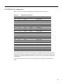
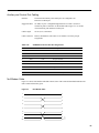
A P P E N D I X
C
Cabling Summary
Introduction
This appendix provides details on the cabling required to connect customer devices to an IGX node.
In all cable references, the transmit direction is from the node, and receive is to the node.
Note EIA/TIA-232 and EIA/TIA-449 existed as recommended standards RS-232 and RS-449
before the Electronics Industries Association (EIA) and Telecommunications Industry Association
(TIA) accepted them as standards.
UXM-E Cabling
The cabling for the UXM-E appears in Table C-1.
Table C-1
UXM-E Cable Model Numbers and Descriptions
Model Number
Description
CAB-SMF-Y-SC
Single mode fiber Y-cable with SC male connectors
CAB-T3E3-PL-Y
SMB-BNC Y-cable, Posi-Lok SMB female connector on Y
end and BNC female connector on tail end
CAB-T3E3-PL-Y-6
Bundle of 6 SMB-BNC Y-cable
CAB-T3E3-PL-Y-12
Bundle of 12 SMB-BNC Y-cable
CAB-SMF-SC-x
Standard single mode fiber cable with SC male connectors, x ft
= 10, 25, 50, 75, 100
CAB-MMF-SC-x
Standard Multi Mode Fiber cable with SC male connectors, x
ft = 10, 25, 50, 75, 100
CAB-T3E3-PL-AD
SMB-BNC adaptor cable 72 inch
CAB-T3E3-PL-AD-6
Bundle of 6 SMB-to-BNC adaptor cable
CAB-T3E3-PL-AD-12
Bundle of 12 SMB-to-BNC adaptor cable
CAB-5607-10=
DB-15/Y Cable/M15-F15 10 Feet
CAB-5614-x
T1/M15-M15 Xover, x ft = 10, 25, 50, 75, 100
CAB-5616-x
T1/M15-M15, x ft = 10, 25, 50, 75, 100
CAB-5685-10=
E1/Y Cable 10 Feet
-1
T1 Cabling
Trunk cables connect the customer DSX-1 crossconnect point or T1-E1 Channel Service Unit (CSU)
to the IGX node at the BC-T1 or BC-E1 back card. Refer to Table C-2 for details.
Table C-2
T1 Trunk/Circuit Line Cabling Specification
Cable Parameter
Description
Cable Type:
Western Electric 22 AWG, ABAM individually shielded twisted pair. Two
pair per T1 line (1 transmit and 1 receive).
Cable Connector:
Male DB-15 subminiature. See Table C-3 for pinouts. The connector
pinouts are the same for both the BA-T1 and the MT3 Distribution Panel.
Maximum Cable Length:
533 ft (162 m.) maximum between the node and the first repeater or CSU.
Table C-3
T1 Connector Pin Assignments
Pin No.
Description
1
Transmit, Tip
2
Transmit Pair Shield
3
Receive, Tip
4
Receive Pair Shield
9
Transmit, Ring
11
Receive, Ring
E1 Cabling
E1 trunk cables connect the customer DSX-1 crossconnect point or E1 Channel Service Unit (CSU)
to the node at the back card. Note that variations exist in the pin assignments for some interfaces:
Table C-6 and Table C-7 show the D-connector pinouts for the CVM, NTM, UFM, UVM, and FRM.
Table C-4
E1 Trunk/Circuit Line Cabling Specification
Cable Parameter
Description
Cable Type:
75-ohm coaxial cable for balanced line or 100–120-ohm twisted pair for
unbalanced line. Balanced lines use two cables per E1 port.
Cable Connector:
Two female BNC for balanced connection; male DB-15 for unbalanced
connection. See Table C-5, Table C-6, and Table C-7 for pinouts.
Max. Cable Length:
E1 output complies with G.703, so attenuation must not exceed –6dB at
1024 kHz (applies to 75 ohm coax or 120 ohm twisted pair). Maximum
length is 100 meters between the IGX node and the first repeater or CSU.
Table C-5
E1 Connector Pin Assignments (Balanced)
Connector
Description
Rx BNC
Receive E1 from trunk
Tx BNC
Transmit E1 to trunk
-2 Cisco IGX 8400 Series Installation and Configuration, Release 9.3.0
Table C-6
E1 D-Connector Pinout, CVM and NTM Back Cards
Pin No.
Description
1
Receive, Tip
2
Receive Pair Shield
3
Transmit, Tip
9
Receive, Ring
10
Transmit Pair Shield
11
Transmit, Ring
Table C-7
E1 D-Connector Pinout, FRM, UFM, and UVM Back Cards
Pin No.
Description
1
Transmit, Tip
2
Transmit Pair Shield
3
Receive, Tip
4
Receive Pair Shield
9
Transmit, Ring
11
Receive, Ring
TTC JJ-20 (J1) Cabling
Table C-8 and Table C-9 describes the J1 cabling and the TTC connector pinouts, respectively.
Table C-8
Japanese J1 Cabling
Cable Parameter
Description
Cable Type:
110-ohm, twisted pair for balanced; 2 cable pairs (1 transmit, 1 receive) per TTC.
Cable Connection:
Male DB-15 for balanced connection. See Table C-9 for pinouts.
Max. Cable Length:
Maximum length depends on signal attenuation, which cannot exceed 13 dB.
Table C-9
TTC Connector Pin Assignments (Balanced)
Pin No.
Description
2
Send Tip S(T)
9
Send Ring S(R)
4
Receive Tip R(T)
11
Receive Ring R(R)
1
Ground
-3
Y1 Trunk Cabling
Table C-10 and Table C-11 describe the Y1 cable and the connector pin assignments, respectively.
Table C-10
Japanese Y1 Cabling
Pin No.
Description
Cable Type:
110 ohm twisted pair, balanced operation. Two cable pairs
(1 transmit, 1 receive) per Y1 line.
Cable Connection:
Male DB-15. See Table C-11 for pinouts.
Max. Cable Length:
Maximum cable length is determined by Vp-p (Voltage peak-to-peak). The
maximum permissible value is 1 Vp-p.
Table C-11
Y Trunk Connector Pin Assignments (Balanced)
Pin No.
Description
2
Transmit Tip T(A)
9
Transmit Ring T(B)
4
Receive Tip R(A)
11
Receive Ring R(B)
1
Shield
Subrate (SR) Cabling
This section lists general data for the subrate cabling and the pinouts for different types of interfaces
that support subrate operation. Table C-12 contains general specifications for the subrate cabling.
Table C-13, Table C-14, and Table C-15 list the pinouts for V.11, V.35, and EIA/TIA-449 interfaces,
respectively.
Table C-12
Subrate Trunk Cabling Specification
Cable Parameter
Description
Cable Type:
100–120-ohm twisted pair telephone cable.
Cable Connector:
V.11, DB-15 subminiature, male.
V.35, 34 pin M block (Winchester), male.
MIL188/RS-449, DB-37 subminiature, male.
See Table C-13 through Table C-15 for pinouts.
Max. Cable Length:
Depends on operating speed. Ranges are 400 meters for 256 Kbps though
50 meters for 1.92 Mbps.
-4 Cisco IGX 8400 Series Installation and Configuration, Release 9.3.0
Table C-13
SR Connector Pin Assignments (V.11)
Pin No.
Description
1
Shield ground
2
TX-A
9
TX-B
3
CA
10
CB
4
RX-A
11
RX-B
5
IA
12
IB
6
SA
13
SB
7
not used
8
Signal ground
14
not used
15
not used
Table C-14
SR Connector Pin Assignments (V.35)
Pin No.
Name
Source
Description
A
Gnd.
both
Protective (Shield) ground
B
Sig. Gnd.
both
Signal ground
C
RTS
DTE
Request to Send
D
CTS
DCE
Clear to Send
E
DSR
DCE
Data Set Ready
F
DCD
DCE
Data Carrier Detect (RLSD)
H
DTR
DTE
Data Terminal Ready
J
RI
DCE
Ring Indicator
K
TM
DCE
Test Mode
L-N
not used
P/S
TxD
DTE
Transmit Data from DTE
R/T
RxD
DCE
Received Data to DTE
U/W
XTC
DTE
External Transmitter Clock
V/X
RxC
DCE
Receiver Clock
Y/AA
TxC
DCE
Transmitter Clock
BB-EE
not used
-5
Table C-15
SR Connector Pin Assignments (EIA/TIA-449)
Pin No.
IGX Name
1
Frm. Gnd.
2
SI
4/22
Source
Description
Both
Shield Ground
SI
DCE
Signaling Rate Indicator (to DTE)
TxD
SD
DTE
Transmit Data from DTE
5/23
TxC
ST
DCE
Transmitter Clock
6/24
RxD
RD
DCE
Received Data to DTE
7/25
RTS
RS
DTE
Request to Send
8/26
RxC
RT
DCE
Receiver Clock
9/27
CTS
CS
DCE
Clear to Send
10
LL
LL
DTE
Local Loopback
11/29
DSR
DM
DCE
Data Set Ready
12/30
DTR
TR
DTE
Data Terminal Ready
13/31
DCD
RR
DCE
Data Carrier Detect (RLSD)
14
RL
RL
DTE
Remote Loopback
15
RI
IC
DCE
Ring Indicator
16
SF
SF
DTE
Signal Rate Select (to DCE)
17/35
XTC
TT
DTE
External Transmitter Clock
18
TM
TM
DCE
Test Mode
19
Sig. Gnd.
SG
Both
Signal Ground
RC
DCE
Receive Common
20
EIA Name
28
BSY
IS
DTE
Busy (in service)
32
SS
SS
DTE
Select Standby
33
SQ
SQ
DCE
Signal Quality Detect
34
NS
NS
DTE
New Synchronization
36
SB
SB
DCE
Standby Indicator
SC
DTE
Send Common
37
3, 21
Table C-16
Spare
T3 Connector Pin Assignments
Connector
Description
Rx BNC
Receive T3 from trunk
Tx BNC
Transmit T3 to trunk
-6 Cisco IGX 8400 Series Installation and Configuration, Release 9.3.0
UFM Cabling
Table C-17 lists the cables that can connect to the UFM back cards for synchronous and
asynchronous circuits.
Table C-17
UFM Data Cables
Cable Parameter
Description
Cable type:
Standard V.35 or X.21
Cable connectors:
X.21 DTE: DB-60, male (provides two X.21 ports)
X.21 DCE: DB-60, male (provides two X.21 ports)
V.35 DTE: DB-60, male (provides two V.35 ports)
V.35 DCE: DB-60, male (provides two V.35 ports)
HSSI: DB-50, male
Maximum cable length:
Not to exceed interface standards
UFI X.21 and V.35 DTE Port Pin Assignments
Table C-18 lists the UFI X.21 and V.35 DTE pin assignments at the DB-60 connector on the card.
Table C-18
UFI X.21 and V.35 DTE Port Pin Assignments
Pin No.
Name
Source
Direction
Description
7/14
SG
Both
—
Signal Ground
9/22
RxC
DCE
Input
Receive Clock
5/18
TxC
DCE
Input
Transmit Clock
3/16
RxD
DCE
Input
Receive Data
2/15
TxD
DTE
Output
Transmit Data
6/19
XTC
DTE
Output
External Transmit Clock
4/17
DTR
DTE
Output
Data Terminal Ready
10/23
DSR
DCE
Input
Data Set Ready
11
RTS
DTE
Output
Request To Send
24
CTS
DCE
Input
Clear To Send
12
LLB
DTE
Output
Local Loopback Command
13
RLB
DTE
Output
Remote Loopback
26
TM
DTE
Output
Test Mode
20
SG
Both
—
Signal Ground
25
DCD
DCE
Input
Data Carrier Detect
1
—
DCE
Input
Port in DCE Mode
-7
UFI X.21 and V.35 DCE Port Pin Assignments
Table C-19 lists the UFI X.21 and V.35 DCE pin assignments at the DB-60 connector on the card.
Table C-19
UFI X.21 and V.35 DCE port Pin Assignments
Pin No.
Name
Source
Direction
Description
7/14
SG
Both
—
Signal Ground
8/21
RxC
DCE
Output
Receive Clock
6/19
TxC
DCE
Output
Transmit Clock
3/16
TxD
DTE
Input
Transmit Data
2/15
RxD
DCE
Output
Receive Data
9/22
XTC
DTE
Input
External Transmit Clock
4/17
DSR
DCE
Output
Data Set Ready
10/23
DTR
DTE
Input
Data Terminal Ready
11
CTS
DCE
Output
Clear To Send
24
RTS
DTE
Input
Request To Send
25
LLB
DTE
Input
Local Loopback Command
26
RLB
DTE
Input
Remote Loopback
13
TM
DTE
Output
Test Mode
20
SG
Both
—
Signal Ground
12
DCD
DCE
Output
Data Carrier Detect
1
—
DTE
Input
Port in DTE Mode
-8 Cisco IGX 8400 Series Installation and Configuration, Release 9.3.0
V.35 DCE Female Cable Pin Assignments
Table C-20 lists the V.35 DCE female cable pin assignments.
Table C-20
UFM V.35 DCE Female Cable Pin Assignments
Signal
Pin No. (from J3)
Wire
Pin No. (to J1)
Signal
Signal ground
55/56
Shorting group
Signal ground
Signal ground
50/51
Shorting group
Signal ground
Shield ground
46
Shield
A
Shield ground
v11-TXD
17/18
Twisted Pair
#1
T/R
RD
v11-TXCOUT
19/20
Twisted Pair
#2
AA/Y
SCT
v11-RXCOUT
21/22
Twisted Pair
#3
X/V
SCR
v11-RXCIN
25/26
Twisted Pair
#4
W/U
SCTE
v11-RXD
27/28
Twisted Pair
#5
S/P
SD
v28-DSR/v28-CTS
34/35
Twisted Pair
#6
H/C
DTR/RTS
v28-RTS/v28-DTR
42/43
Twisted Pair
#7
D/E
CTS/DSR
v28-LL-DCD/Not used
44/16
Twisted Pair
#8
F/B
RLSD/—
v28-DCD-LL/Not used
33/16
Twisted Pair
#9
K/B
LT/Not used
Shield ground
45
Shield
A
Shield ground
v11-TXD
3/4
Twisted Pair
#1
T/R
RD
v11-TXCOUT
5/6
Twisted Pair
#2
AA/Y
SCT
v11-RXCOUT
7/8
Twisted Pair
#3
X/V
SCR
v11-RXCIN
29/30
Twisted Pair
#4
W/U
SCTE
v11-RXD
31/32
Twisted Pair
#5
S/P
SD
v28-DSR/v28-CTS
38/36
Twisted Pair
#6
H/C
DTR/RTS
v28-RTS/v28-DTR
40/41
Twisted Pair
#7
D/E
CTS/DSR
v28-LL-DCD/Not used
39/15
Twisted Pair
#8
F/B
RLSD/—
v28-DCD-LL/Not used
37/15
Twisted Pair
#9
K/B
LT/Not used
-9
Note The CAB-2-V.35 DCE '1' Winchester connector corresponds to an odd UFM-U port and the
CAB-2-V.35 DCE '2' Winchester connector corresponds to an even UFM-Uport.
-10 Cisco IGX 8400 Series Installation and Configuration, Release 9.3.0
V.35 DTE Male Cable Pin Assignments
Table C-21 lists the V.35 DTE male cable pin assignments.
Table C-21
UFM V.35 DTE Male Cable Pin Assignments
Signal
Pin No. (from J3)
Wire
Pin No. (to J1)
Signal
p2_mode_0/Ground/p2_mode_DCE
55/56/54
Shorting group
p1_mode_0/Ground/p1_mode_DCE
50/51/52
Shorting group
Shield ground
46
Shield
A
Shield ground
v11-TXD
17/18
Twisted Pair
#1
S/P
SD
v11-TXCOUT
19/20
Twisted Pair
#2
W/U
SCTE
v11-TXCIN
23/24
Twisted Pair
#3
AA/Y
SCT
v11-RXCIN
25/26
Twisted Pair
#4
X/V
SCR
v11-RXD
27/28
Twisted Pair
#5
T/R
RD
v28-DSR/v28-CTS
34/35
Twisted Pair
#6
E/D
DSR/CTS
v28-RTS/v28-DTR
42/43
Twisted Pair
#7
C/H
RTS/DTR
v28-LL-DCD/Not used
44/16
Twisted Pair
#8
K/B
LT/—
v28-DCD-LL/Not used
33/16
Twisted Pair
#9
F/B
RLSD/Not used
Shield ground
45
Shield
A
Shield ground
v11-TXD
3/4
Twisted Pair
#1
S/P
SD
v11-TXCOUT
5/6
Twisted Pair
#2
W/U
SCTE
v11-TXCIN
13/14
Twisted Pair
#3
AA/Y
SCT
v11-TXCIN/v11-RXCIN
29/30
Twisted Pair
#4
X/V
SCR
v11-RXD
31/32
Twisted Pair
#5
T/R
RD
v28-DSR/v28-CTS
38/36
Twisted Pair
#6
E/D
DSR/CTS
v28-RTS/v28-DTR
42/43
Twisted Pair
#7
C/H
RTS/DTR
v28-LL-DCD/Not used
39/15
Twisted Pair
#8
K/B
LT/—
v28-DCD-LL/Not used
37/15
Twisted Pair
#9
F/B
RLSD/Not used
-11
Note The CAB-2-V.35 DTE '1' Winchester connector corresponds to an odd UFM-U port and the
CAB-2-V.35 DTE '2' Winchester connector corresponds to an even UFM-U port.
-12 Cisco IGX 8400 Series Installation and Configuration, Release 9.3.0
UFI HSSI Port Pin Assignments
Table C-22 lists the UFI HSSI pin assignments at the DB-50 connector on the card.
Table C-22
UFI HSSI Pin Assignments
Pin No.
Name
Source
Direction
Description
1/26
SG
Both
—
Signal Ground
2/27
RT
DCE
Output
Receive Timing
3/28
CA
DCE
Output
DCE Available
4/29
RD
DCE
Output
Receive Data
5/30
LC
DTE
Output
DCE loop Request
6/31
ST
DCE
Output
Send Timing
7/32
SG
Both
—
Signal Ground
8/33
TA
DTE
Input
DTE Available
9/34
TT
DCE
Input
Terminal Timing
10/35
LA
DTE
Input
Loopback Circuit A
11/36
SD
DTE
Input
Send Data
12/37
LB
DTE
Input
Loopback Circuit B
13/38
SG
Both
—
Signal Ground
14/39
DT
DTE
Input
Send Timing in DTE
15 to 18
—
DCE
Output
Undefined: to DCE
19/44
SG
Both
—
Signal Ground
20 to 23
—
DTE
Input
Undefined: from DCE
24/49
TM
DTE
Output
Test Mode
25/50
SG
Both
—
Signal Ground
The UFI-HSSI interface is native DCE. The interface pin assignment is done in such a way that the
UFI interface can be connected to the HSSI interface of a Cisco-Router, which is a native DTE, using
a straight pin-to-pin HSSI standard cable attached to a UFI back card or a Cisco Router in either DTE
or DCE modes.
A UFI card in DCE mode can be connected to any DTE interface using the same standard Cisco
cable.
-13
When UFI is configured in DTE mode, it needs the HSSI-DTE cable to connect to a DCE
interface.The wiring details are shown in Table C-23 for cable number 72-1265-01.
Table C-23
UFI HSSI DTE Pin Assignments
Pin No. J1 to J2
Name
Direction
Description
1/26 to 1/26
SG
—
Signal Ground
2/27 to 9/34
RT/TT
Output
Receive Timing/Terminal Timing
3/28 to 8/33
CA/TA
Output
DCE Available/DTE Available
4/29 to 11/36
RD/SD
Output
Receive Data/Send Data
5/30 to 10/35
LC/LA
Output
DCE loop Request/Loopback Circuit A
6/31 to 14/39
ST/DT
Output
Send Timing/Send Timing in DTE
7/32 to 7/32
SG
—
Signal Ground
8/33 to 3/28
TA/CA
Input
DTE Available/DCE Available
9/34 to 2/27
TT/RT
Input
Terminal Timing/Receive Timing
10/35 to 5/30
LA/LC
Input
Loopback Circuit A/DCE loop Request
11/36 to 4/29
SD/RD
Input
Send Data/Receive Data
12/37 to 24/49
LB/TM
Input
Loopback Circuit B/Test Mode
13/38 to 13/38
SG
—
Signal Ground
14/39 to 6/31
DT/ST
Input
Send Timing in DTE/Send Timing
15 through 18 to
40 through 43
not used
—
Not used
19/44 to 19/44
SG
—
Signal Ground
20 through 23 to
45 through 48
not used
—
Not used
24/49 to 12/37
TM/LB
Output
Test Mode/Loopback Circuit B
25/50 to 25/50
SG
—
Signal Ground
-14 Cisco IGX 8400 Series Installation and Configuration, Release 9.3.0
FRI V.35 Port Pin Assignments
Table C-24 contains a listing of IGX V.35 pin assignments for the Frame Relay FRI card. A standard
V.35 cable is used for this application.
Table C-24
FRI V.35 Port Pin Assignments
Pin No.
Name
Source
Description
A
Gnd.
both
Protective (Shield) ground
B
Sig. Gnd.
both
Signal ground
C
RTS
DTE
Request to Send
D
CTS
DCE
Clear to Send
E
DSR
DCE
Data Set Ready
F
DCD
DCE
Data Carrier Detect
H
DTR
DTE
Data Terminal Ready
L
LLB
DTE
Local Loopback command to user device
N
RLB
DTE
Remote Loopback command to user device
n
TM
DTE
Test Mode indicates user device. ready for test
P/S
TxD
DTE
Transmit Data from DTE
R/T
RxD
DCE
Receive Data to DTE
U/W
XTC
DTE
External Transmitter Clock
V/X
RxC
DCE
Receiver Clock
Y/a
TxC
DCE
Transmitter Clock
Data Cabling
This section contains Table C-25 through Table C-34. These tables describe the cables for the LDM
and HDM card sets. (The HDM and LDM are high-speed and low-speed data cards.)
Table C-25
Synchronous Data Cables
Cable Parameter
Description
Cable Type:
Standard EIA/TIA-232C/D (V.24), V.35, or EIA/TIA-449/422 (with
adaptor cable for X.21).
Cable Connectors:
EIA/TIA-232C/D (V.24): DB-25 Subminiature, male.
V.35: 34 pin M block-type (Winchester), male.
EIA/TIA-449/422: DB-37 Subminiature, male.
Max. Cable Length:
Not to exceed interface standards.
-15
HDM EIA/TIA-232D Port Pin Assignments
Table C-26 contains a listing of IGX EIA/TIA-232D port pin assignments for the HDM’s interface
card—the SDI. A standard EIA/TIA-232 cable works in this application.
Table C-26
HDM EIA/TIA-232D Port Pin Assignments
Pin No.
IGX Name
EIA Name
Source
Description
1
Frame Gnd.
AA
Both
Frame Ground
2
TxD
BA
DTE
Transmit Data from DTE
3
RxD
BB
DCE
Received Data to DTE
4
RTS
CA
DTE
Request to Send
5
CTS
CB
DCE
Clear to Send
6
DSR
CC
DCE
Data Set Ready
7
Signal Ground
8
DCD
9
CF
DCE
Data Carrier Detect (RLSD)
+VS
Both
+12 volt test
10
-VS
Both
–12 volt test
11
QM
DCE
Equalizer Mode (to DTE only)
12
SDCD
SCF
DCE
Secondary Data Carrier Detect
13
SCTS
SCB
DCE
Secondary Clear to Send
14
STxD
SBA
DTE
Secondary Transmit Data
15
TxC
DB
DCE
Transmitter Clock
16
SRxD
SBB
DCE
Secondary Received Data
17
RxC
DD
DCE
Receiver Clock
18
RL
DTE
Remote Loop Back
19
SRTS
SCA
DTE
Secondary Request to Send
20
DTR
CD
DTE
Data Terminal Ready
21
SQ
CG
DCE
Signal Quality Detect
22
RI
CE
DCE
Ring Indicator
23
SF
CH
DTE
Signal Rate Select (to DCE)
23
SI
CI
DCE
Signaling Rate Indicator (to DTE)
24
XTC
DA
DTE
External Transmitter Clock
25
TST
DCE
Test Indicator
-16 Cisco IGX 8400 Series Installation and Configuration, Release 9.3.0
HDM EIA/TIA-232C (V.24) Port Pin Assignments
Table C-27 contains a listing of IGX EIA/TIA-232C port pin assignments for the SDI data card. A
standard EIA/TIA-232 (V.24) cable is used for this application.
Table C-27
HDM EIA/TIA-232C Port Pin Assignments
Pin No.
IGX Name
EIA Name
Source
Description
1
Frame Gnd.
AA
Both
Frame Ground
2
TxD
BA
DTE
Transmit Data from DTE
3
RxD
BB
DCE
Received Data to DTE
4
RTS
CA
DTE
Request to Send
5
CTS
CB
DCE
Clear to Send
6
DSR
CC
DCE
Data Set Ready
7
Signal Ground
8
DCD
9
CF
DCE
Data Carrier Detect (RLSD)
+VS
Both
+12 volt test
10
-VS
Both
–12 volt test
11
QM Pin 11
DCE
DTE
Equalizer Mode (to DTE)
Pin 11 to (DCE)
12
SDCD
SCF
DCE
Secondary Data Carrier Detect
13
SCTS
SCB
DCE
Secondary Clear to Send
14
STxD
SBA
DTE
Secondary Transmit Data
15
TxC
DB
DCE
Transmitter Clock
16
SRxD
SBB
DCE
Secondary Received Data
17
RxC
DD
DCE
Receiver Clock
18
DCR
DCE
Divided Receiver Clock
19
SRTS
SCA
DTE
Secondary Request to Send
20
DTR
CD
DTE
Data Terminal Ready
21
SQ
CG
DCE
Signal Quality Detect
22
RI
CE
DCE
Ring Indicator
23
SFCI
CH
CI
DTE
DCE
Signal Rate Select (to DCE)
Signaling Rate Indicator (to DTE)
24
XTC
DA
DTE
External Transmitter Clock
25
BSY
DTE
Busy (in service)
-17
HDM EIA/TIA-449/422 Port Pin Assignments
Table C-28 contains a listing of IGX EIA/TIA-449/422 port pin assignments. A standard
EIA/TIA-449 cable is used for this application unless the interface is X.21.
Table C-28
Pin No.
HDM EIA/TIA-449/422 Port Pin Assignments
IGX Name
EIA Name
1
2
SI
SI
Source
Description
Both
Shield Ground
DCE
Signaling Rate Indicator (to DTE)
3
Spare
4/22
TxD
SD
DTE
Transmit Data from DTE
5/23
TxC
ST
DCE
Transmitter Clock
6/24
RxD
RD
DCE
Received Data to DTE
7/25
RTS
RS
DTE
Request to Send
8/26
RxC
RT
DCE
Receiver Clock
9/27
CTS
CS
DCE
Clear to Send
10
LL
LL
DTE
Local Loopback
11/29
DSR
DM
DCE
Data Set Ready
12/30
DTR
TR
DTE
Data Terminal Ready
13/31
DCD
RR
DCE
Data Carrier Detect (RLSD)
14
RL
RL
DTE
Remote Loopback
15
RI
IC
DCE
Ring Indicator
16
SF
SF
DTE
Signal Rate Select (to DCE)
17/35
XTC
TT
DTE
External Transmitter Clock
18
TM
TM
DTE
Test Mode
19
SG
Both
Signal Ground
20
RC
DCE
Receive Common
21
Spare
28
BSY
IS
DTE
Busy (in service)
32
SS
SS
DTE
Select Standby
33
SQ
SQ
DCE
Signal Quality Detect
34
NS
NS
DTE
New Synchronization
36
SB
SB
DCE
Standby Indicator
SC
DTE
Send Common
37
See Table C-29 and Table C-30 for Wire Lists for adapter cables for X.21 application. This adapter
cable is available in two models: one is used when the HDM/SDI card set operates as a DCE and the
other when the HDM/SDI operates as a DTE. It has a male DB-37 on the IGX end and a female
DB-15 (DCE) or male DB-15 (DTE) on the user-end.
-18 Cisco IGX 8400 Series Installation and Configuration, Release 9.3.0
Table C-29
Wiring List, SDI EIA/TIA-449-to-X.21 Adapter Cable (for EIA/TIA-449 DCE)
DB-37 Pin No.
(SDI)
IGX Name
DB-15 Pin No.
(User)
Description
1
Drain
1
Frame Ground
4
TxD-A
2
Transmit Data from DTE
22
TxD-B
9
Transmit Data from DTE
6
RxD-A
4
Receive Data to DTE
24
RxD-B
11
Receive Data to DTE
7
RTS-A
3
Request to Send
25
RTS-B
10
Request to Send
9
CTS-A
5
Clear to Send
27
CTS-A
12
Clear to Send
8
RxC-A
6
Receive Clock
26
RxC-B
13
Receive Clock
19
SG
8
Signal Ground
Table C-30
Wiring List, SDI EIA/TIA-449 to X.21 Adapter Cable (for EIA/TIA-449 DTE)
DB-37 Pin No.
(SDI)
IGX Name
DB-15 Pin No.
(User)
Description
1
Drain
1
Frame Ground
4
TxD-A
2
Transmit Data from DTE
22
TxD-B
9
Transmit Data from DTE
6
RxD-A
4
Receive Data to DTE
24
RxD-B
11
Receive Data to DTE
7
RTS-A
3
Request to Send
25
RTS-B
10
Request to Send
9
CTS-A
5
Clear to Send
27
CTS-A
12
Clear to Send
5
TxC-A
6
Transmit Clock
23
TxC-B
13
Transmit Clock
19
SG
8
Signal Ground
5 to 8
TxC-A
Receive Clock1
23 to 26
TxC-B
Receive Clock *
1. Loops Receive Clock to Transmit Clock when necessary.
-19
HDM V.35 Port Pin Assignments
Table C-31 contains a listing of IGX V.35 Port pin assignments for the SDI card. A standard V.35
cable works this application.
Table C-31
HDM V.35 Port Pin Assignments
Pin No.
Name
Source
Description
A
Gnd.
both
Protective (Shield) ground
B
Sig. Gnd.
both
Signal ground
C
RTS
DTE
Request to Send
D
CTS
DCE
Clear to Send
E
DSR
DCE
Data Set Ready
F
DCD
DCE
Data Carrier Detect (RLSD)
H
DTR
DTE
Data Terminal Ready
J
RI
DCE
Ring Indicator
K
TM
DCE
Test Mode
P/S
TxD
DTE
Transmit Data from DTE
R/T
RxD
DCE
Receive Data to DTE
U/W
XTC
DTE
External Transmitter Clock
V/X
RxC
DCE
Receiver Clock
Y/a
TxC
DCE
Transmitter Clock
-20 Cisco IGX 8400 Series Installation and Configuration, Release 9.3.0
LDM EIA/TIA-232 Port Pin Assignments
Table C-32 lists the EIA/TIA-232 port pin assignments at the DB-15 connector on the LDM’s LDI
back card. The LDM card supports a limited subset of EIA control leads. The LDI always uses a
DCE or DTE DB-15-to-DB-25 adapter cable. Refer to Table C-33 and Table C-34 for wiring lists
and the pin-outs for the standard male DB-25 connector to the user data device.
Table C-32
LDM EIA/TIA-232 Port Pin Assignments
Pin No.
IGX Name
EIA Name
Source
Description
1
Shield
AA
Both
Frame Ground
2
TxD
BA
DTE
Transmit Data from DTE
3
CTS
CB
DCE
Clear to Send
4
RxD
BB
DCE
Received Data to DTE
5
RTS
CA
DTE
Request to Send
6
XTC
DB
DCE
Transmitter Clock
7
RxC
DD
DCE
Receiver Clock
8
SG
AB
Both
Signal Ground
9
DSR
CC
DCE
Data Set Ready
10
DTR
CD
DTE
Data Terminal Ready
11
+VS
Both
+12V test voltage
12
–VS
Both
–12V test voltage
13
DCD
DCE
Data Carrier Detect (RLSD)
14
RL
DTE
Remote Loop (for modem loopback)
15
MOD
CF
Mode Select for cable (DTE or DCE)
-21
Table C-33
Wiring List, DB-15 to DB-25 Adapter Cable (LDI as DTE)1
DB-15 Pin No.
(LDI)
IGX Name
DB-25 Pin No.
(User)
Description
1
Frm. Gnd.
1
Frame Ground
2
RxD
3
Received Data to DTE
3
RTS
4
Request to Send
4
TxD
2
Transmit Data from DTE
5
CTS
5
Clear to Send
6
XTC
24
External Transmit Clock
7
RxC
17
Receive Clock
8
SG
7
Signal Ground
9
DTR
20
Data Terminal Ready
10
DSR
6
Data Set Ready
11
+VS
9
+12V test voltage 2
12
–VS
10
–12V test voltage 2
13
DCD
8
Data Carrier Detect (RLSD)
14
RL
21
Remote Loop output
15
MOD
n.c.
Connects internally to DB-15-8
(3)
LL
18
Local Loop output 3
1. You can order this cable in lengths of 10 ft., 25 ft., 50 ft., 75 ft., and 100 ft. The Cisco model number is
CAB-5626E-xx, where xx is the length, as follows: 10=10 ft.; 25=25 ft.; 50=50 ft.; 75=75 ft., and 00=100 ft.
2. You can use one of these pins to force a control pin to stay high or low.
3. No LDI local loop output is available. Try using DTR output: DB-15-9.
Note Two adapter cables are available for the LDI card. The choice of cable determines whether
the LDI card functions as a DCE or as a DTE. These can be ordered from Cisco Systems or made
by the customer. Make sure the correct cable is used for the type of user device connected.
-22 Cisco IGX 8400 Series Installation and Configuration, Release 9.3.0
Wiring List, DB-15 to DB-25 Adapter Cable (LDI as DCE)1
Table C-34
DB-15 Pin No.
(LDI)
IGX Name
DB-25 Pin No.
(User)
Description
1
Shield
1
Frame Ground
2
TxD
2
Transmit Data from DTE
3
CTS
5
Clear to Send
4
RxD
3
Receive Data to DTE
5
RTS
4
Request to Send
6
RxC
17
Receive Clock, connects to DB-25-152
7
XTC
24
External Transmit Clock
8
SG
7
Signal Ground
9
DSR
6
Data Set Ready
10
DTR
20
Data Terminal Ready
11
+VS
9
+12V test voltage 3
12
–VS
10
–12V test voltage 3
13
not connected
not connected
not used
14
DCD
8
Data Carrier Detect (RLSD)
MOD
n.c.
Mode Select, no connection for DCE cable
TxC
15
Transmit Clock, connects to DB-25-17 2
15
not connected
2
1. You can order this cable in lengths of 10 ft., 25 ft., 50 ft., 75 ft., and 100 ft. The Cisco model number is
CAB-5625-xx, where xx is the length, as follows: 10=10 ft.; 25=25 ft.; 50=50 ft.; 75=75 ft., and 00=100 ft.
2. Pins 15 and 17 connect through a jumper.
3. You can use one of these pins to force a control pin to stay high or low.
Redundancy Cabling
Table C-35 lists the Y-cables used for redundancy for IGX back cards.
Table C-35
Redundancy Y-Cables
Cable
Used On
Cisco Part No.
EIA/TIA-232C
SDI
5624
EIA/TIA-232D
SDI
5624
EIA/TIA-232
LDI
5629
V.35
SDI
5635
V.35
SDI
special DTE/DCE jumper
EIA/TIA-422/449
SDI
5644
T1
BC-T1
5607
E1
BC-E1
5685
-23
Power Cabling
This section describes AC and DC power cabling between the IGX node and the power source.
Source-end connector information is not available for all countries, so local codes must be known or
obtained by either the customer or installer. Table C-36 describes AC power cabling. Table C-37
describes DC power cabling.
Table C-36
AC Power Cabling
Piece
Standard
Cable:
Cisco provides a 6-foot (1.8m), 3-conductor cord with an IEC 320 C-19 appliance
coupler for mating with the IGX node on the system end. The other end of the power
cord should be a grounding-type attachment plug as described in the paragraphs that
follow.
Connector:
In North America and Japan:
For IGX 8320/8430: NEMA L6-20 Twist Lock
For IGX 8410: NEMA L6-20 Twist Lock or NEMA 5-15
For Continental Europe: CEE 7/7 (Schuko)
For Italy: CEI 23-16/VII (16 Amp plug)
For United Kingdom and Ireland: BS 1363
For Australia and New Zealand: AS 3112
For those countries not appearing in the preceding list, use a power cord with an IEC
320 C-19 appliance coupler for the system-end and an appropriate grounding-type
attachment plug at the other end in accordance with local standards.
Table C-37
DC Power Cabling
Piece
Standard
Cable:
You provide a 3-conductor cord. The other end of the power cord should be a
grounding-type attachment. The wire gauge is 10 to 12 AWG or 4 sq. mm.
Connector:
At the system end, Cisco provides a pluggable wire block with screw-type
clamping for the three conductors. The customer or installer attaches the
customer supplied wiring to this block.
SCM Cabling
SCM cabling connects the Network Management ports on the SCM to Cisco WAN Manager
(formerly StrataView Plus) Network Management computers, control terminals, and modems. This
cabling also provides the connection for an external clock source.
-24 Cisco IGX 8400 Series Installation and Configuration, Release 9.3.0
Auxiliary and Control Port Cabling
Interface:
The IGX SCM auxiliary and control ports are configured as an
EIA/TIA-232 DCE port.
Suggested Cable:
24 AWG, 25-pair. A straight-through EIA/TIA-232 cable is used for a
terminal or printer connection. A null modem cable (Figure C-1) is needed
when interfacing with modems on either port.
Cable Length:
50 feet (15 m.) maximum.
Cable Connector:
DB-25, subminiature, male. Table C-38 contains a list of the port pin
assignments.
Table C-38
SCM AUX and Control Port Pin Assignments
Pin No.
Name
Source
Description
1
FG
both
Frame Ground
2
TxD
DTE
Transmit Data
3
RxD
DCE
Receive Data
4
RTS
DTE
Request to Send
5
CTS
DCE
Clear to Send
6
DSR
DCE
Data Set Ready
7
SG
both
Signal Ground
8
CD
DCE
Carrier Detect
20
DTR
DTE
Data Term Ready
Null Modem Cable
Figure C-1 shows a null modem cable that connects some of the 1200 and 2400 baud modems to the
IGX Control and Auxiliary ports.
Null Modem Cable
1
1
2
2
3
3
4
4
5
5
6
6
7
7
8
8
20
20
H8377
Figure C-1
-25
External Clock Input Cabling
Two separate clock inputs exist, and can be used simultaneously on the IGX. They are labelled
External-1 and External-2. Both clock inputs require an EIA/TIA 422 balanced square wave signal
at either 1.544 or 2.048 MB per second.
Note Standard DS1 or E1 BITS clock sources using AMI bipolar pulse stream signals are not
compatible with IGX external clock inputs.
Table C-39
External Clock Cabling
Cable Parameter
Interface
Suggested cable
Cable connector
Maximum cable length
Table C-40
Pin No.
1
9
2
3
11
4
5
Description
Balanced EIA/TIA 422
24 AWG, individually shielded, 1- or 2-pair
DB-15, subminiature, male. See Table C-40 for pinouts
50 ft (15 m)
External Clock Connector Pin Assignments
Description
External Clk 1-A
External Clk 1-B
Shield ground pair 1
External Clk 2-A
External Clk 2-B
Shield ground pair 1
8.192 MHz test output (factory use only)
External Alarm Cabling
This cable connects network alarm outputs to either the DTI Faceplate or the ARI card Alarm
connector. Table C-41 lists particulars for the physical interface. Table C-42 lists the pinouts for the
network alarm outputs. In Table C-42, note that pins whose names end in “A” are normally open,
and pins whose names end in “C” are common.
Table C-41
External Alarm Interface
Parameter
Description
Interface:
Dry-contact relay closure.
Wire:
24 AWG, shielded, 10 pairs.
Connector:
DB-37, Subminiature, male.
-26 Cisco IGX 8400 Series Installation and Configuration, Release 9.3.0
Table C-42
Network Alarm Pin Assignments
Pin No.
Name
Description
1
CHASSIS
Chassis Ground
2
Reserved
3
NWMAJA
Network Major Alarm
4
NWMAJC
Network Major Alarm
5
Reserved
6
Reserved
7
Reserved
8
Reserved
9
Reserved
10
MNVISA
11
12
Minor Visual Alarm
Reserved
MNVISC
Minor Visual Alarm
13
Reserved
14
Unused
15
Unused
16
MJAUDC
Major Audible Alarm
17
MJAUDA
Major Audible Alarm
18
Unused
19
Unused
20
Reserved
21
Reserved
22
Reserved
23
NWMINA
24
25
Network Minor Alarm
Reserved
NWMINC
Network Minor Alarm
26
Reserved
27
Reserved
28
Reserved
29
MNAUDA
30
31
Minor Audible Alarm
Reserved
MNAUDC
Minor Audible Alarm
32
Unused
33
Unused
34
Unused
35
MJVISC
Major Visual Alarm
36
MJVISA
Major Visual Alarm
37
Unused
-27
Standard IGX Cables
Table C-43 lists the cables you can order directly from Cisco Systems. The length of the cable
appears as a suffix to the model number. For example 5610-50 indicates a 50-foot cable. Cables are
generally available in standard lengths of 10 ft (3 m.), 25 ft (7.6 m.), 50 ft (15 m.), 75 ft (22.8 m.)
and 100 ft (30 m.) Lengths of 101 ft. (30 m.) to 600 ft. (183 m.) are available on a special order.
Where applicable, Table C-43 indicates the connector gender (male-female) as well as the number
of pins. For example T1/M15-M15 indicates a cable terminated with a male DB-15 at both ends.
Table C-43
Standard IGX Cables Available From Cisco
Model
Description
Usage
5608
T1, pigtail to RJ48
CSU to telco demarc
5614
T1/M15-M15 turnover
E1 trunk to CSU
5616
T1/M15-M15
5680
BNC-DB-15
E1 trunk
5685
T1/M15-M15 turnover, Y-cable
E1 trunk redundancy
5630
V.35/M34-F34
Subrate trunk or data circuit
5636E
V.35 Y-cable
Subrate trunk or data circuit redundancy
5645
EIA/TIA-422/X.21 adapter-DTE
IGX is DTE
5646
EIA/TIA-422/X.21 adapter-DCE
IGX is DCE
5644
EIA/TIA-422 Y-cable
Subrate trunk or data circuit redundancy
5695
X.21/DB-15 Y-cable
Subrate trunk or data circuit redundancy
5620
EIA/TIA-232/M25-F25
Control port to control terminal, StrataView
Plus, or external window device
5621
EIA/TIA-232/M25-M25 special
Control or Aux. port to modem
5625
V.35/M15-F25
LDI8 (DCE) to data device
5626E
V.35/M15-M25
LDI8 (DTE) to data device
5629
EIA/TIA 232/M15-M15, Y-cable
LDI redundancy
Note Most cables listed as T1 can also be used for E1 service.
Note Transmit direction is towards the “Y” trunk.
-28 Cisco IGX 8400 Series Installation and Configuration, Release 9.3.0