1
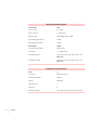
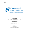
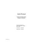
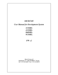
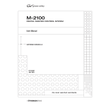
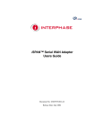
User’s Manual:
Universal Communication Controller
Synchronous to Asynchronous Communication Interface
Software Revision 2.004b
•
•
• I
•
•
•
Copyright ©2000, ADD-Engineering B.V.
Online version copyright © 2000
All rights reserved.
Printed in the Netherlands
This document is protected by Copyright Protection Laws. The online
version of this document may be freely printed and distributed internally,
but cannot be modified, in whole or in part, or included in any other work
without prior written consent from ADD-Engineering B.V.
Limitation of Liability
ADD-Engineering B.V. makes NO WARRANTY, EXPRESSED or
IMPLIED, with respect to this user-manual, and any related items, its
quality, performance, merchantability, or fitness for any particular use. It is
solely the purchaser’s responsibility to determine its suitability for any
particular use. Information contained in this document is subject to change
without notice.
Trademark credits
The following are trademarks of ADD-Engineering B.V.
Universal Communication Controller
SyncMate
ClockMate
II
•
•
•
•
•
•
Contents
••••••
I
Chapter 1
Introduction
3
Functional Description
Specification Overview
Chapter 2
Controls and Display
Keyboard
9
Keylock
10
Display
11
Chapter 3
Preset Setup
Edit
13
Copy
13
Chapter 4
Channel Setup
15
Channel Type
15
Bit Encoding
16
Bit Order
17
Sync Length
19
Sync Pattern
19
Strip Sync
19
Frame-Length
20
Strip/Insert Bit
21
4
5
9
13
•
•
• 1
•
•
•
SizeHeader
22
Clock-source
23
Sync Speed
23
Idle-State
24
Checksum-Mode
25
Async-Speed
25
Signal Polarity DCE
26
Signal Polarity DTE
27
Channel Mode
28
Chapter 5
Channel Diagnostics
29
All Channels
29
Per Channel HDLC
30
Per Channel Universal/Transparent
Chapter 6
Controller Info
Chapter 7
Performance Info
Chapter 8
Connecting the UCC
Power
38
Control Port
38
DTE Ports
38
DCE Ports
39
35
37
Appendix A
Warranty and Maintenance
Appendix B
Cables and Connectors
Appendix C
Menu Structure
Index
2
33
•
•
• Contents
•
•
•
67
51
41
45
31
Chapter 1
Introduction
••••••
Congratulations on purchasing your Universal Communication Controller
from ADD-Engineering. The Universal Communication Controller
combines dedicated communication hardware with on-board data
processing software to provide an efficient means of interfacing
asynchronous Data Terminal Equipment to synchronous Data
Communication Equipment. By doing this the Universal Communication
Controller off-load communications overhead from your Data Terminal
Equipment’s CPU for optimum system performance.
•
•
• 3
•
•
•
Functional Description
The Universal Communication Controller is a device that establishes the
interface from standard asynchronous serial ports (the ones which are
usually standard on computer systems) to standard as well as "non-standard"
synchronous systems (non-standard in terms of Commercially Of The Shelf
equipment). The UCC can interface 8 synchronous systems to 8
asynchronous systems simultaneously. Apart from the configurable
"Universal-mode"1, the UCC now also provides an HDLC and a transparent
interface mode. To provide flexibility and create a wide adaptation level
within these different modes, the UCC has a number of parameters which
can be altered to interface to specific protocols. Synchronisation word, bit
encoding and bit stripping are only a couple of these parameters. Though the
UCC is designed from a total new concept, a lot of its functionality is
comparable to that of the SyncMate and the ClockMate. The UCC provides
more functionality, flexibility, stability, configurability, ease of installation
and fault check mechanisms. Above all that the UCC also provides a
mechanism to remote monitor/configure the unit by means of a serial
terminal. System configuration security is guaranteed by a keylock that can
disable access to menu’s which affect the units behaviour.
1. Universal mode: only operating mode available on UCC’s with a software revision
prior to 2.004b
4
•
•
•
•
•
•
Chapter 1
Specification Overview
DCE / Asynchronous Interface
Ports
8
Connector
DB25 DCE (female)
Electrical Interface
RS-232
Speed
1200, 2400, 4800, 9600, 19k2 and 115k2
bps
Start/Stop bits
1
Data bits
8
Bit order
LSB-first, MSB-first
Flow control
CTS/RTS
Input buffer
128 bytes / 8kb (HDLC)
Output buffer
32 bytes / 16kb (HDLC)
Available signals
CTS, RTS, TxD, RxD, DTR, TxC (NA),
RxC (NA), ExC (NA)
Invertable signals
CTS, RTS, TxD, RxD, DTR, TxC (NA),
RxC (NA), ExC (NA)
Specification of DCE interface
DTE / Synchronous Interface
Ports
8
Connector
DB25 DTE (male)
Electrical Interface
RS-232
Speed
600, 1200, 2400, 4800, 9600, 64k bps
Clock mode
Internal, Dpll, External
Clock source
input: TxC, RxC
output: ExC
Specification of DTE interface
Introduction
•
•
• 5
•
•
•
DTE / Synchronous Interface
Flow Control
CTS
Sync Length
6...16 bits
Frame Length
1..1024 bytes
BIt Encoding
NRZ, !NRZ, NRZI, !NRZI
Sync Stripping/Insertion
On/Off
Bit Stripping/ Insertion
On/Off
SizeHeader
On/Off
Checksum Generation
Off/Xor/Xnor
Idle State
1, 0, Alternating
Available signals
CTS, RTS, TxD, RxD, DCD, DTR, TxC,
RxC, ExC
Invertable signals
CTS, RTS, TxD, RxD, DCD, DTR, TxC,
RxC, ExC
Specification of DTE interface
Control Port / Asynchronous
Ports
1
Connector
DB9 DTE (male)
Electrical Interface
RS-232
Speed
9600 bps
Start/Stop bits
1
Data bits
8
Available signals
TxD, RxD, RTS, DTR, DSR, DCD, CTS
Specification of control port interface
6
•
•
•
•
•
•
Chapter 1
Power Requirements
AC Input
95V - 135V (110V switch position)
180V - 265V (230V switch position)
Net Frequency
47 Hz - 63 Hz
Power Consumption
25 Watt
Power requirements
Display
Type
LCD Super Twisted
Display pattern
2 * 40 characters
Backlight color
Green
Display specifications
Dimensions
Case
19 inch rack mountable unit
Width
19 inch (482.60 mm)
Height
3 HU (133.35 mm)
Depth
250 mm
Dimensions
Introduction
•
•
• 7
•
•
•
8
•
•
•
•
•
•
Chapter 1
Chapter 2
Controls and Display
••••••
The Universal Communication Controller is controlled by four front panel
keys and via the 9 pin SUB-D connector on the back of the device (control
port). To provide a means of disabling access to functions that could change
the operation of the device a keylock has been installed. Input from the
keyboard and output to the display is processed in exactly the same manner
on the serial control port.
L
U
LOCK/UNLOCK
A
B
C
D
Front-panel of the UCC
Keyboard
The front panel keyboard contains four keys marked A, B, C, and D. The
keys enable a user to step through the menu’s. All the keys have their
“serial”-equivalent (input on the control-port) that can be used
simultaneously.
•
•
• 9
•
•
•
A - key
This key is the general Escape key, when a user wants to quit the current
menu (and move one level up in the menu-hierarchy in the case that is
possible). The “serial”-equivalent for this key is the “left-arrow” control
key.
B - key
This key is the down/left key, when a user wants to move to the previous
menu or previous value. The “serial”-equivalent for this key is the “downarrow” control key.
C - key
This key is the up/right key, when a user wants to move to the next menu or
next value. The “serial”-equivalent for this key is the “up-arrow” control
key.
D - key
This key is the accept/enter-menu/toggle key, when a user wants to accept
the selected value. However, in some menu’s the key is used to toggle
“binary” values. The “serial”-equivalent for this key is the “right-arrow”
control key.
Keylock
The keylock provides a means of control to disable access to
menu’s/functions which can alter the operation of the device. Menu’s that do
not enable the user to change the operation of the device will always be
accessible.
Locked
The L is the Locked position. The user is granted access to the “Channel
Diagnostics” and the “Controller Info” menu’s only. The user is not able to
chenge the operational mode of the device, nor is the user able to view
settings of the device.
Unlocked
The U is the Unlocked position. The user is granted access to all the menu’s,
no restrictions apply.
•
•
10 ••
•
•
Chapter 2
Note:
In case you have lost both keys of your UCC’s keylock, please contact ADDEngineering for a new set of keys.
Display
The LCD with backlight contains information on the current selected
menu/parameter and the selectable values. In general, the first row displays
the parameter and the second row displays the selectable values. The output
to the serial control port is identical (is a copy of) the information on the
display.
Controls and Display
•
•
• 11
•
•
•
•
•
12 ••
•
•
Chapter 2
Chapter 3
Preset Setup
••••••
Setting up presets enables the user to set up a kind of profiles for specific
protocols or configurations. By setting up a preset (editing) and copy this
preset to the channels which need to be configured as selected in the preset,
the user can avoid the cumbersome job of setting up a number of channels
with the same configuration. The latter also indicates that a preset’s
configuration can be copied to more than one channel.
Edit
Enables the user to edit the selected preset, editing the preset will not change
configurations of channels which configuration was copied from this preset.
Editing the selected preset will not change the correct functioning of the
channels currently active.
A preset needs to be selected before the actual editing can be initiated.
The parameters which are selectable and configurable are the same as for the
parameters in “Channel Setup”. For a complete functional description of
these parameters please see the “Channel Setup” chapter.
Copy
Enables the user to copy the selected preset to one of the eight channels,
copying the preset will change configurations of the destination channel.
A preset needs to be selected before a destination channel can be selected.
•
•
• 13
•
•
•
•
•
14 ••
•
•
Chapter 3
Chapter 4
Channel Setup
••••••
The flexibility of the Universal Communication Controller allows a user to
configure the device for a wide range of military and non-military protocols
and electrical interfaces. The parameters that are variable and their effects
in the behaviour of the UCC are described hereunder.
Channel Type
Channel type selects the type of “protocol” for that specific channel. After
selecting a specific channel type, the parameters that are of no use for
the selected mode of operation are hidden. Hence, there will be no menuitem displaying this parameter. The UCC provides 3 types of channels,
Universal, HDLC and Transparant.
•
Universal
The standard operating mode used for processing different military
protocols.
•
HDLC
The operating mode providing an interface to HDLC.
•
Transparent
The operating mode that provides a transparant interface from asynchronous
to synchronous and vice versa.
•
•
• 15
•
•
•
Bit Encoding
Receiver
Bit-encoding for the receiver can be described as the way the line-state is
decoded to a received bit. With the UCC it is possible to specify 4 different
bit-encoding methods, NRZ, !NRZ, !NRZI and NRZI.
•
NRZ
Generally known as Non Return to Zero, the line-state is directly decoded
to form a bit. A ‘1’ on the physical line is "decoded" to a bit with the value
‘1’. A ‘0’ on the physical line is "decoded" to a bit with the value ‘0’.
•
!NRZ
Almost the same as NRZ but in this case all bits are simply inverted. A ‘1’
on the physical line is "decoded" to a bit with the value ‘0’ in memory. A ‘0’
on the physical line is "decoded" to a bit with the value ‘1’.
•
NRZI
Generally known as Non Return to Zero Inverted. Although the name
implies that it is just the inverted version of NRZ, there is a more significant
difference between these two. To decode the line-state to a bit in NRZI
requires knowledge of the previous line-state. If there is a difference
between the previous line-state and the actual line-state then it is decoded to
a bit with the value ‘0’. If there is no difference between the previous and
the actual line-state then it is decoded to a bit with the value ‘1’. In short,
transitions will be decoded to form a bit with the value ‘0’ and steady states
will be decoded to form a bit with the value ‘1’.
•
!NRZI
Almost the same as NRZI but in this case all bits are simply inverted.
Transitions will be decoded to form a bit with the value ‘1’ and steady states
will be decoded to form a bit with the value ‘0’.
•
•
16 ••
•
•
Chapter 4
Transmitter
Bit-encoding for the transmitter can be described as the way the bits which
need to be transmitted are encoded to a line state.
•
NRZ
Generally known as Non Return to Zero, the bit is directly encoded to form
a line-state. A bit with the value ‘1’ is encoded to the physical line-state 1.
A bit with the value ‘0’ is encoded to the physical line-state ‘0’.
•
!NRZ
Almost the same as NRZ but in this case all bits are simply inverted first. A
bit with the value ‘1’ is encoded to the physical line-state ‘0’. A bit with the
value ‘0’ is encoded to the physical line-state ‘1’.
•
NRZI
To encode the bit to transmit to a line-state in NRZI requires knowledge of
the previous line-state. If a bit with the value ‘0’ needs to be encoded then
the line-state should alter, so the actual line-state should be the inverted
version of the previous line-state. If a bit with the value ‘1’ needs to be
encoded the actual line-state should be the same as the previous line-state.
In short, bits with the value ‘0’ will be encoded as transitions and bits with
the value ‘1’ will be encoded as steady-states.
•
!NRZI
Almost the same as NRZI but in this case all bits are simply inverted first.
In short, bits with the value ‘1’ will be encoded as transitions and bits with
the value ‘0’ will be encoded as steady-states.
Bit Order
Receiver
For the receiver the bit-order can best be described as the order in which the
synchronously received bits are submitted to the asynchronous receiver. The
most commonly used bit-order is LSB-first, however some applications
require the opposite.
•
LSB-FIRST
Channel Setup
•
•
• 17
•
•
•
The bit which is received first at the synchronous line will be placed at the
LSB-position of the byte which will be submitted to the asynchronous
receiver. No bit-reversal is taking place.
•
MSB-FIRST
The bit which is received first at the synchronous line will be placed at the
MSB-position of the byte which will be submitted to the asynchronous
receiver. In short it means that bit 0 becomes bit 7, bit 1 becomes bit 6 and
so on.
Transmitter
For the transmitter the bit-order can best be described as the order in which
the asynchronously received bytes are transmitted by the synchronous
transmitter. The most commonly used bit-order is LSB-first, however some
applications require the opposite.
•
LSB-FIRST
The bit at the LSB-position of the byte received at the asynchronous input
will be transmitted first by the synchronous transmitter. No bit-reversal is
taking place.
•
MSB-FIRST
The bit at the MSB-position of the byte received at the asynchronous input
will be transmitted first by the synchronous transmitter. In short it means
that bit 0 becomes bit 7, bit 1 becomes bit 6 and so on.
•
•
18 ••
•
•
Chapter 4
Sync Length
Receiver
With Sync-Length the number of bits which form the Sync-Pattern can be
specified. Changes to the number of sync-bits will not erase the SyncPattern.. The Sync-Length is configurable in the range [6..16].
Transmitter
With Sync-Length the number of bits which form the Sync-Pattern can be
specified. Changes to the number of sync-bits will not erase the SyncPattern, the pattern will be truncated. The Sync-Length is configurable in
the range [6..16].
Sync Pattern
Receiver
The Sync-Pattern specifies the sync-word on which the receiver will
synchronise. The sync-pattern is compared after bit-decoding takes place.
When the Sync-Pattern has been received the device is considered to be insync. Bytes will now be submitted to the user asynchronously.
Transmitter
The Sync-Pattern denotes the start of a frame. The pattern will be
transmitted if there are bytes in the internal buffer. If there are less bytes in
the buffer than the specified frame-length, the UCC will transmit the bytes
in the buffer and fill up the remaining bytes (which were not submitted) with
idle bits. The Sync-Pattern is fully user definable.
Strip Sync
To provide the user with the possibility to strip or not strip the sync-word
from the synchronously received data or to insert or not insert the sync-word
into the synchronously transmitted data, this option is implemented in the
UCC.
Receiver
•
OFF
Channel Setup
•
•
• 19
•
•
•
The synchronously received sync-word is submitted to the user via the
asynchronous output. In case the bit-order is reversed the sync-word will
also be reversed.
•
ON
The number of synchronisation bits are stripped from the synchronously
received data. In other words the sync-word is stripped from the data.
Transmitter
•
OFF
Off in this context actually means no-insertion. No insertion of a sync-word
takes place at the synchronous transmitter side. The user has to submit the
sync-word via the asynchronous input port.
•
ON
On means that the sync-word is inserted by the UCC in case a new frame
needs to be transmitted. The sync-word which is inserted is specified by the
pattern "Sync-Pattern". The pattern should be read from left to right with the
left bit transmitted first.
Frame-Length
The frame-length is selectable in the range of [1..1024]. In general the
Frame-Length is the number of bytes the user will submit or can expect
asynchronously. The latter with some exceptions which can be read
hereunder.
Receiver
With the Fame-Length parameter the number of bytes which the user
expects is specified. The number of bytes are submitted to the asynchronous
side. All the bytes which are received are included in the Frame-Length. So,
in case the sync-word is not stripped the Sync-Word will count as part of the
total Frame-Length.
Transmitter
With the Frame-Length parameter the number of bytes which the user will
submit is specified. In case the Sync-Word is not stripped, the Sync-Word
should be submitted by the user via the asynchronous port and thus will
•
•
20 ••
•
•
Chapter 4
count as part of the Frame-Length. However, if a checksum-mode is
selected, one byte less should be submitted while the UCC is generating its
own checksum to be forwarded with the data.
Strip/Insert Bit
Bit stripping is better known as the term bit-stuffing. Specific bits are
stripped from the data at the receiver’s side and inserted at the transmitter’s
side.
Receiver
At the receiver’s side (synchronous) the specified bit will be stripped from
the data. The insert parameter in this menu is of no significance for the
receiver’s side. The bitposition parameter specifies which bit will be
stripped after reception of the Sync-Word. Assuming the Sync-Word is
found and the strip/insert parameter is set to bitposition ‘1’, insert ‘0’. Then
the first bit after the Sync-Word is stripped from the data (in case SyncStripping is also enabled), then the next 8 bits are forwarded to the
asynchronous port and the next "first" bit is stripped from the data. This
continues until all the bytes of the frame are received.
Transmitter
At the transmitter's side (synchronous) the specified bit will be inserted in
the data. The insert parameter in this menu specifies if a ‘0’ or a ‘1’ will be
inserted. Assuming the Sync-Word has already been transmitted (and syncstripping is also enabled) and the strip/insert parameter is set to bitposition
‘1’, insert ‘0’. Then the first bit transmitted after the sync-word will be a ‘0’.
After that a byte which is submitted via the asynchronous port will be
forwarded to the synchronous port and then another ‘0’ will be inserted.
This continues until all the bytes of the frame are transmitted.
Channel Setup
•
•
• 21
•
•
•
SizeHeader
Size header is an option that is only used in HDLC to place the size of the
HDLC-frame in front of the frame itself
Receiver
Places the size of the HDLC frame in front of the frame itself. Maximum
size of the frame is 8192 bytes. The size header is a two byte value (actually
16 bits unsigned) with the MS-Byte being sent first. A user can determine
the end of a HDLC frame by counting the number of bytes received and
compare this to the size of the frame as “decoded” from the size-header.
Transmitter
The size-header parameter is of no significance in the transmitter.
•
•
22 ••
•
•
Chapter 4
Clock-source
With the UCC it is possible to select three different clock-sources. The first
most commonly used is the external (EXT) clock-mode, the second is the
internal (INT) clock-mode and the third and last is the digital pll (DPLL)
clock-mode.
•
INT
The internal clock-mode is used when the UCC should generate the
clocking signals required. The synchronous clock-speed can be selected
from the Sync-Speed menu. The clock which is generated internally is
placed on pin 24 (ETCLK) of the UCC.
•
DPLL
The digital pll clock-mode is used when synchronous data is coming in at a
known synchronous bit-rate but not accompanied by a clock signal. The
synchronous clock-speed can be selected from the Sync-Speed menu. The
clock which is generated internally is placed on pin 24 (ETCLK) of the
UCC. The internally generated clock is synchronised continuously with the
received data, or better with the transitions in this data.
•
EXT
With the external clock-mode clock-signals should be connected to the UCC
at pin 17 (RCLK) and pin 15 (TCLK). The RCLK is timebase related to the
data on pin 3 (RxD) and the TCLK is timebase related to the data on pin 2
(TxD). The TCLK and RCLK need not to be related, however usually they
are.
Receiver
Data is clocked in at the rate specified by the clock-signal.
Transmitter
Data is clocked out at the rate specified by the clock-signal.
Sync Speed
The Sync-Speed parameter of the UCC has only significance if INT
(internal) or DPLL (digital phase locked loop) is enabled. In other cases the
transmit/receive clock submitted will dictate the synchronous speed. Thus,
Channel Setup
•
•
• 23
•
•
•
when using external clock, the user is not limited by the selection of syncspeeds down here. However, there is an upper-limit to the external supplied
synchronous clock which is 9600.
•
600
Data is clocked in and out at 600 Bps.
•
1200
Data is clocked in and out at 1200 Bps.
•
2400
Data is clocked in and out at 2400 Bps.
•
4800
Data is clocked in and out at 4800 Bps.
•
9600
Data is clocked in and out at 9600 Bps.
•
64K
Data is clocked in and out at 64 KBps.
Receiver
Data is clocked in at the selected speed.
Transmitter
Data is clocked out at the selected speed.
Idle-State
The idle-state is used to specify the behaviour of the transmitter in the case
that there are no bytes to transmit. The idle-state is directly related to the
line-state and thus no bit-encoding will take place. There are three possible
idle-states, ‘0’, ‘1’ and ALT.
Receiver
This parameter is of no significance for the receiver.
Transmitter
•
•
•
24 ••
•
•
Chapter 4
‘0’
Idle in zero’s, invalid for NRZI and !NRZI bit encoding methods.
•
‘1’
Idle in one’s, invalid for NRZI and !NRZI bit encoding methods.
•
ALT
Idle in alternating states, normally this is used to keep receivers with DPLL
in sync.
Checksum-Mode
Checksums can be generated by the UCC, it means that the user does not
have to calculate checksums over the data submitted to the UCC. The
checksum is transmitted as the last byte of a frame. The checksum-mode has
three options, OFF, XOR and XNOR.
Receiver
The checksum-mode parameter is of no significance in the receiver.
Transmitter
The checksum calculated using the method defined above is attached to the
frame as a last byte.
•
OFF
No checksum is attached to the frame
•
XOR
An XOR (exclusive or) will be performed over all the bytes in the frame
(except the sync-word).
•
XNOR
An XNOR (inverted exclusive or) will be performed over all the bytes in the
frame (except the sync-word).
Async-Speed
The speed selected in this menu is used to transmit and receive
asynchronous data via the asynchronous ports. Regardless of the settings in
this menu, the control port of the UCC will always come up with 9600 Bd.,
this is fixed and can not be changed.
•
1200
Channel Setup
•
•
• 25
•
•
•
Asynchronous bitrate is 1200, No Parity, 8 Bits, 1 Stop bit.
•
2400
Asynchronous bitrate is 2400, No Parity, 8 Bits, 1 Stop bit.
•
4800
Asynchronous bitrate is 4800, No Parity, 8 Bits, 1 Stop bit.
•
9600
Asynchronous bitrate is 9600, No Parity, 8 Bits, 1 Stop bit.
•
19200
Asynchronous bitrate is 19200, No Parity, 8 Bits, 1 Stop bit.
•
115K2
Asynchronous bitrate is 115200, No Parity, 8 Bits, 1 Stop bit.
Receiver
The asynchronous receive rate.
Transmitter
The asynchronous transmit rate.
Signal Polarity DCE
The polarity of the data, status and clock signals (although clock signals are
not available at the channel’s DCE side) is selectable in this menu.
•
RX
The RxD line can be inverted (pin 2)
•
TX
The TxD line can be inverted (pin 3)
•
RTS
The RTS line can be inverted (pin 4)
•
CTS
The CTS line can be inverted (pin 5)
•
DTR
The DTR line can be inverted (pin 20)
•
•
•
26 ••
•
•
Chapter 4
TXC
The TxC line can be inverted (pin 15), currently of no significance
•
RXC
The RxC line can be inverted (pin 17), currently of no significance
•
EX
The ETX line can be inverted (pin 24), currently of no significance
Transmitter
The inversion of data signals, clock signals or status signals has no special
consequences except the ones a user might expect from the setting.
For instance if the user inverts the TxD line, it is logical that other systems
connected to the device will not be able to communicate with the UCC
anymore when these devices use the standard polarity (note: not the data on
the line gets inverted but the line gets inverted, so start and stop bits will be
inverted to!).
Receiver
The inversion of data signals, clock signals or status signals has no special
consequences except the ones a user might expect from the setting.
Signal Polarity DTE
The polarity of the data, status and clock signals is selectable in this menu.
•
RX
The RxD line can be inverted (pin 3)
•
TX
The TxD line can be inverted (pin 2)
•
RTS
The RTS line can be inverted (pin 4)
•
CTS
The CTS line can be inverted (pin 5)
•
DTR
The DTR line can be inverted (pin 20)
•
CD
The CD line can be inverted (pin 8)
Channel Setup
•
•
• 27
•
•
•
•
TXC
The TxC line can be inverted (pin 15)
•
RXC
The RxC line can be inverted (pin 17)
•
EX
The ETX line can be inverted (pin 24)
Channel Mode
Channel Mode allows a user to disable/enable one of the eight channels on
the UCC.
•
Active
The channel is active and fully functional.
•
Down
The channel is powered down, the synchronous DTE side of the channel
will not produce a clocking signal (internal, dpll mode). The asynchronous
DCE side of the channel will hold CTS logic low (the connected device is
not allowed to send data).
Transmitter
See general description.
Receiver
See general description.
•
•
28 ••
•
•
Chapter 4
Chapter 5
Channel Diagnostics
••••••
The Universal Communication Controller has a number of built in features
which reflect the actual state of the channels.The UCC has per channel
based statistics and above that a general all channel overview. Both features
can be very helpful in resolving/detecting a problem.
All Channels
This menu provides the user with a general overview of the status of all
channels at once. It is selected by selecting ALL at the “Channel
Diagnostics” menu.
Display contents when selecting Channel Diagnostics ALL
T
Indicates the synchronous transmitter of the channel. If the indicator below
the T is rotating the synchronous transmitter is transmitting a frame. If the
indicator is blinking ‘-’ on and off then the CTS line of the synchronous
transmitter is disabled. No data can be send on the synchronous channel if
this situation exists. Make sure RTS is connected to CTS and that the signals
are not inverted by means of “DTE Channel Polarity”.
•
•
• 29
•
•
•
R
Indicates the synchronous receiver of the channel. If the indicator below the
R is rotating the synchronous receiver is receiving a frame.
Per Channel HDLC
This menu provides the user with a more detailed channel based overview.
It is selected by selecting one of the eight possible channels at the “Channel
Diagnostics” menu
Display contents when selecting Channel Diagnostics of one HDLC-channel
Channel
Indicates the selected channel for which the statistics are valid. The number
behind “Channel” could be in the range of 1..8.
Down
Reflects the channel mode, this could be Down and Active.
CRC-Error
Indicates the number of CRC-errors that occurred on that particular channel.
The CRC that is used on the HDLC channels is the standard CRC-CCITT
(16 bits).
Frm-Tx
Reflects the number of frames already transmitted. For every frame
submitted through the asynchronous DCE port this counter should
increment with one.
Frm-Rx
Indicates the number of frames already received. An increment at this
counter means that another frame is submitted to the asynchronous DCE
port by the UCC.
•
•
30 ••
•
•
Chapter 5
Per Channel Universal/Transparent
This menu provides the user with a more detailed channel based overview.
It is selected by selecting one of the eight possible channels at the “Channel
Diagnostics” menu
Display contents when selecting Channel Diagnostics of one channel
Channel
Indicates the selected channel for which the statistics are valid. The number
behind “Channel” could be in the range of 1..8.
Down
Reflects the channel mode, this could be Down and Active.
Idles-Rx
Indicates the number of bytes which are received but were not part of a
frame or a synchronisation word. If the line is in idle-state (and clocks are
configured correctly) this counter should increment. For the transparent
channel-type the Idles-Rx will not increment durring reception because in
transparent mode the unit can not distinguish frames from idles.
Frm-Tx
Reflects the number of frames already transmitted. For every frame
submitted through the asynchronous DCE port this counter should
increment with one.
Frm-Rx
Indicates the number of frames already received. An increment at this
counter means that another frame is submitted to the asynchronous DCE
port by the UCC. When using the transparent channel-type the Frm-Rx
indicates the number of bytes received on the synchronous interface.
Channel Diagnostics
•
•
• 31
•
•
•
•
•
32 ••
•
•
Chapter 5
Chapter 6
Controller Info
••••••
The Universal Communication Controller has a built-in menu item for
determining the software revision and serial number of the device. This
menu is called the "Controller Info"-menu. The information displayed in
this menu can be very helpful in case of particular problems. It allows the
customer service group at ADD-Engineering to determine the specific
details of your system.
Display contents when selecting Controller Info
Bios Rev
Indicates the bios revision in the BBB field.
Application Rev
Indicates the application revision in the AAAAA field.
Device Serialnumber
Indicates the 10 digit serial number of the device in the DDDDDDDDDD
field.
•
•
• 33
•
•
•
•
•
34 ••
•
•
Chapter 6
Chapter 7
Performance Info
••••••
The Universal Communication Controller has a built-in menu item for
monitoring the CPU-load during operation of the unit. Since the UCC is
highly optimized for its tasks the CPU-load displayed in this menu will
probably be less than 50 % with all synchronous channels running on 64k
and asynchronous channels running on 115k2. Do not be alarmed if the
CPU-load indicates 0.0 % !
Display contents when selecting Performance Info
CPU-load
Indicates the CPU-load in percents, the load is also displayed by the bargraph on the second line of the display.
•
•
• 35
•
•
•
•
•
36 ••
•
•
Chapter 7
Chapter 8
Connecting the UCC
••••••
The back-panel of the Universal Communication Controller has a large
number of connectors. There are female (socket) DB25 connectors, male
(plug) DB25 connectors and a male (plug) DB9 connector. The DB25
connectors are grouped by “equipment” type. The male (plug) connectors
represent the DTE (Data Terminal Equipment) function of the channels and
the female (socket) connectors represent the DCE (Data Communication
Equipment) function of the channels. The DB9 connector represents the
control-port which enables remote-control. A description of these
connectors together with the power-inlet connector is given in this chapter.
control-port dce-port
dte-port
1
2
1
2
3
4
3
4
5
6
5
6
7
8
7
8
power inlet
Back-panel of the UCC
•
•
• 37
•
•
•
Power
The power to the UCC is delivered through a IEC/EURO style power inlet.
Operating voltage can be switched to 110V/60 Hz as well as to 220 V/50 Hz.
Before connecting the UCC to the mains-power, make sure the correct
selection has been made for the operating voltage.
Note
Impoper selection of the operating voltage (in relation to the mains-power)
causes damage to the unit.
Control Port
The control port is the male DB9 connector. The port enables the user to
have the same functionality as with the local front panel keyboard and
display, however the controls can now be remote. By connecting a remote
VT100 (or VT100 emulating) terminal settings can be changed and
diagnostics can viewed remote. However, settings can never be changed in
case the keylock is on lock (L) position. Communication to the remote
terminal is asynchronous with the following settings: 9600 Bd, 8 bits, no
parity, 1 stop bit. This configuration can not be changed. Pinouts of the
control port can be found in the appendices
DTE Ports
The DTE-ports are the male DB25 connectors. The ports are called DTEports because the pinning is exactly as on a DTE device. The DTE ports are
all synchronous. These are the ports which in most configurations interface
to a modem (DCE-device). DTE-port number 1 is connected internally to
DCE-port number 1 to form a channel, DTE-port number 2 is connected
internally to DCE-port number 2, etc. Pinouts of the DTE-ports can be found
in the appendices.
Note
For correct operation of the UCC, it is of major concern that the CTS signal
inputs on the DTE-ports (pin 5) have a defined value which indicates Clear To
Send, either CTS is tied to RTS (pin 4) directly or CTS is tied to the CTS output
•
•
38 ••
•
•
Chapter 8
of the modem. In case the CTS signal is not asserted, the unit will not be able to
send any data synchronously. Such a situation will be indicated on the display
by a blinking ‘-’ (see Channel Diagnostics).
DCE Ports
The DCE-ports are the female DB25 connectors. The ports are called DCEports because the pinning is exactly as on a DCE device. The DCE ports are
all asynchronous. These are the ports which in most configurations interface
to a computer-serial port (DTE-device). DCE-port number 1 is connected
internally to DTE-port number 1 to form a channel, DCE-port number 2 is
connected internally to DTE-port number 2, etc. Pinouts of the DCE ports
can be found in the appendices.
Connecting the UCC
•
•
• 39
•
•
•
•
•
40 ••
•
•
Chapter 8
Appendix A
Warranty and Maintenance
••••••
Warranty Information
Hardware
All ADD-Engineering B.V.’s hardware products are covered by a one year
warranty from the original date of purchase. Warranty coverage includes:
Telephone support. Free phone support on any hardware product for one
year after initial product purchase. ADD-Engineering’s Customer Service
and Support (CSS) hours are 9:00 am to 5:00 pm, Monday through Friday.
Rapid replacement. Upon CSS phone verification of hardware failure
within the first 90 days after purchase, ADD-Engineering will issue a return
material authorization (RMA) number for rapid replacement. If the failed
unit is in stock, a replacement unit will be shipped within one business day.
If the failed unit is not in stock, it will receive the highest priority for repair
once ADD-Engineering receives the unit.
Extended maintenance option. Extends the standard warranty coverage,
including rapid replacement, to three years when purchased within 90 days
of initial product purchase.
•
•
• 41
•
•
•
Out of warranty repair service is available for a per-product flat fee. Typical
turnaround for out-of-warranty repairs is four to six weeks from date of
factory receipt.
Limited Hardware Warranty. ADD-Engineering warrants its hardware
products to be free from defect in materials and workmanship. ADDEngineering will repair or replace (at its option) all defective product
returned freight pre-paid, in original packaging, to its factory in Rotterdam,
The Netherlands within one (1) year. ADD-Engineering reserves the right to
ship replacement units from our inventory of reconditioned units. All other
warranties, expressed or implied, are limited to the restrictions of this
warranty. Product abuse, alteration, or misuse invalidates all warranties.
This warranty does not cover damages incurred by natural or electrical
forces exceeding the stated product specifications. In no event will ADDEngineering’s warranty liability exceed the purchase price of the product.
No liability is assumed for any consequential damages resulting from the
use of any ADD-Engineering product.
This warranty is in lieu of all other warranties, including but not limited to
the warranties of merchantability and fitness for a particular purpose.
National, state and local laws may offer rights in addition to those stated
above.
•
•
42 ••
•
•
Appendix A
Product Information Worksheet
Please record the following information about your Universal
Communication Controller.
UCC Serial number:
Purchase date:
Warranty and Maintenance
•
•
• 43
•
•
•
•
•
44 ••
•
•
Appendix A
Appendix B
Cables and Connectors
••••••
This appendix provides necessary background information for making
connections to the serial ports on the UCC. It discusses modem and null
modem connectors, the standard RS-232 pinouts, and describes some
typical cables
Two terms used frequently throughout this appendix are
• Data Communication Equipment (DCE)
• Data Terminal Equipment (DTE)
DCE peripheral devices usually refer to modems
DTE devices include terminals, computers and printers.
•
•
• 45
•
•
•
Cabling Overview
To connect a peripheral device to the Universal Communication Controller,
you need an interface cable to run electrical signals from one of the DB-25
connectors to the peripheral device. ADD-Engineering does not supply this
cable. You can purchase ready-made cables at your local computer store or
make them on your own
DCE and DTE devices send and receive signals through different pins. The
UCC is at one side configured to be a DCE device and on the other side to
be a DTE device. In general, when connecting a DCE-device to the DTEinterface of the UCC and when connecting a DTE-device to the DCEinterface of the UCC, use straight through cables.
•
•
46 ••
•
•
Appendix B
Serial Connector Pinouts
Terminals, modems and printers typically communicate through an RS-232
(serial) interface. All of the Universal Communication Controller’s
synchronous ports are DTE type RS-232 compatible serial connectors.
13
1
14
25
Serial connector Pin Diagram (male DTE)
Pin Number
RS-232 Signal
V.24 Signal
Direction
2
TxD
103
Output
3
RxD
104
Input
4
RTS
105
Output
5
CTS
106
Input
6
DSR
107
Input
7
Signal GND
-
None
8
DCD
109
Input
20
DTR
108/2
Output
15
TxCin
114
Input
17
RxCin
115
Input
24
TxCout
113
Output
Serial connector Pinout (male DTE)
Cables and Connectors
•
•
• 47
•
•
•
Signal
Description
TxD
Transmit Data. Sends data to peripheral device
RxD
Receive Data. Receives data from the peripheral
RTS
Request To Send. Signal asking if peripheral device is ready
to receive data
CTS
Clear To Send. Signal from the peripheral device indicating
readiness to accept data
DSR
Data Set Ready. Signal from the peripheral indicating the
status.
Signal GND
Signal Ground. Provides reference level for other signals
DCD
Data Carrier Detect. Signal indicating that the peripheral
device has detected a signal from the remote peripheral
device over the datacommunications channel
RxCin
Receive Data Clock. Input for receiver signal element timing
from a synchronous DCE-device.
TxCin
Transmit Data Clock. Input for transmitter signal element
timing from a synchronous DCE-device
DTR
Data Terminal Ready. Indicates that the local device is ready
to communicate
TxCout
Transmit Data Clock. Output for transmitter signal element
timing generated on the UCC.
Pin Signal Description
•
•
48 ••
•
•
Appendix B
All of the Universal Communication Controller’s asynchronous ports are
DCE type RS-232 compatible serial connectors.
13
1
25
14
Serial connector Pin Diagram (female DCE)
Pin Number
RS-232 Signal
V.24 Signal
Direction
2
RxD
103
Inputt
3
TxD
104
Output
4
RTS
105
Input
5
CTS
106
Output
7
Signal GND
-
None
20
DTR
108/2
Input
15
TxCin
114
NA
17
RxCin
115
NA
24
TxCout
113
NA
Serial connector Pinout (female DCE)
Cables and Connectors
•
•
• 49
•
•
•
•
•
50 ••
•
•
Appendix B
Appendix C
Menu Structure
••••••
The menu structure of the Universal Communication Controller is almost
self-explaining. However, for reference, a detailed overview is given in this
appendix. The structure is given in the form of diagrams. For every
transition from one menu to another menu the key (from the keyboard) is
given as a condition for that transition
•
•
• 51
•
•
•
•
•
•
•
52 ••
Appendix C
D to enter menu
Function: Preset Setup
A to exit menu
B
C
D to enter menu
Function: Channel Setup
A to exit menu
B
C
Function: Channel Diagnostics
D to enter menu
A to exit menu
B
C
D to enter menu
Function: Controller Info
A to exit menu
B
Function: Performance Info
C
D to enter menu
A to exit menu
Main Menu Structure
Function: Preset Setup
A
D
C
Preset : EDIT
EDIT copy
A
B
D
use B & C to Preset Setup : PRESET1
select preset PRESET1 preset2 preset3 preset4
A
D
Edit : Bit Encoding
!NRZI
from here functions the
same as channel setup
Preset : EDIT
edit COPY
A
D
Preset Setup : PRESET1
PRESET1 preset2 preset3 preset4
A
D
Copy Preset 1 to Channel : 1
12345678
D
Store settings to flash
Preset Setup Menu Structure
use B & C to
select preset
use B & C to
select channel
Menu Structure
•
•
• 53
•
•
•
•
•
•
•
54 ••
Appendix C
Function: Channel Setup
A
D
use B & C to
select channel
Channel Setup : 1
12345678
A
D
C
Edit : Channel Type
UNIVERSAL
A
B
D
Channel Type: UNIVERSAL
UNIVERSAL hdlc transparent
A
use B & C to
select value
C
Edit : BitEncoding
!NRZI
cont...
B
D
use B & C to
select value
BitEncoding: !NRZI
nrz !nrz nrzi !NRZI
D
D
Store settings to flash
Store settings to flash
Channel Setup Menu Structure-1
C
.....
B
C
Edit : BitOrder
LSB-FIRST
A
cont...
B
D
BitOrder : LSB-FIRST
LSB-FIRST msb-first
use B & C to
select value
D
Store settings to flash
Channel Setup Menu Structure-2
Menu Structure
•
•
• 55
•
•
•
•
•
•
•
56 ••
Appendix C
C
.....
B
C
Edit : Sync Length
8
A
B
D
Sync Length : 8
8
D
Store settings to flash
Channel Setup Menu Structure-3
A
use B & C to
decrease or
increase
C
Edit : Sync Pattern
00000000
cont...
B
D
Sync Pattern : 00000000
00000000
use B & C to select bit,
use D to toggle bit and
store to flash
C
.....
B
C
Edit : Strip Sync
OFF
A
B
D
A
use B & C to
select value
Strip Sync : OFF
OFF on
C
Edit : Frame Length
16
cont...
B
D
use B & C to
decrease or
increase value
Frame Length : 16
16
D
D
Store settings to flash
Store settings to flash
Channel Setup Menu Structure-4
Menu Structure
•
•
• 57
•
•
•
•
•
•
•
58 ••
Appendix C
C
.....
B
C
Edit : Strip/Insert Bit
Bitposition 0, Insert 0
A
B
D
A
use B & C to
select value
Strip/Insert Bit : 00
Bitposition 0, Insert 0
C
Edit : Size Header
ON
cont...
B
D
use B & C to
select value
Size Header : ON
off ON
D
D
Store settings to flash
Store settings to flash
Channel Setup Menu Structure-5
C
.....
B
C
Edit : Clock Source
EXT
A
cont...
B
D
use B & C to
select value
Clock Source : EXT
int dpll EXT
D
Store settings to flash
Channel Setup Menu Structure-6
Menu Structure
•
•
• 59
•
•
•
•
•
•
•
60 ••
Appendix C
C
.....
B
C
Edit : Sync Speed
1200
A
B
D
A
use B & C to
select value
Sync Speed : 1200
600 1200 2400 4800 9600
C
Edit : Idle State
ALTERNATING
cont...
B
D
Idle State : ALTERNATING
ones zeros ALTERNATING
use B & C to
select value
D
D
Store settings to flash
Store settings to flash
Channel Setup Menu Structure-7
C
.....
B
C
Edit : Checksum Mode
OFF
A
B
D
A
use B & C to
select value
Checksum Mode : OFF
OFF xor xnor
C
Edit : Async Baudrate
9600
cont...
B
D
Async Baudrate : 9600
1200 2400 4800 9600 19200
D
D
Store settings to flash
Store settings to flash
Channel Setup Menu Structure-8
use B & C to
select value
Menu Structure
•
•
• 61
•
•
•
•
•
•
•
62 ••
Appendix C
C
.....
B
Edit : Signal Polarity DCE
TX RX RTS CTS DTR TXC RXC EX
A
D
Signal Polarity DCE : 00000000
TX rx rts cts dtr txc rxc ex
use B & C to select signal,
D to toggle and store to flash
Channel Setup Menu Structure-9
C
B
Edit : Signal Polarity DTE
TX RX RTS CTS DTR CD TXC RXC EX
A
D
Signal Polarity DTE : 000000000
TX rx rts cts dtr cd txc rxc ex
use B & C to select signal,
D to toggle and store to flash
C
cont...
B
.....
C
B
Edit : Channel Mode
ACTIVE
A
D
use B & C to
select value
Channel Mode : ACTIVE
ACTIVE down
D
Store settings to flash
Channel Setup Menu Structure-10
Menu Structure
•
•
• 63
•
•
•
•
•
•
•
64 ••
Appendix C
Function: Channel Diagnostics
A
D
Channel Diagnostics : 1
1 2 3 4 5 6 7 8 all
A
use B & C to
select channel
D
Channel 1: Active
Frm-Tx: 0
Idles Rx: 0
Frm-Rx: 0
T1R T2R T3R T4R T5R T6R T7R T8R
depending on selection of single channel or all channels
Channel Diagnostics Menu Structure
Function: Controller Info
A
D
Bios Rev: BBB Application Rev: A.AAA
Device Serialnumber: DDDDDDDDDD
Controller Info Menu Structure
Menu Structure
•
•
• 65
•
•
•
•
•
•
•
66 ••
Appendix C
Function: Performance Info
A
CPU load: 12.1 %
#####
Performance Info Menu Structure
D
Index
••••••
A
D
all channel overview 29
alternating 25
application revision 33
Asynchronous Interface 5
asynchronous ports 49
Async-Speed 25
DB9 connector 37
details of your system
digital pll clock 23
Dimensions 7
Display 7
DPLL 23
B
E
back-panel 37
bios revision 33,
Bit-encoding 16
bit-order 17
bit-stuffing 21
blinking ‘-’ 29
35
C
Cabling Overview 46
Channel Diagnostics 29
Channel Mode 28
channel mode 30, 31
Channel Setup 15
Checksum-Mode 25
ClockMate 4
clock-sources 23
Control Port 6
control port 38
control port settings 38
Controller Info 33
copy 13
CRC 30
CTS signal 38
edit 13
EXT 23
external clock
33
23
F
female DB25 39
frame-length 20
Frm-Rx 30, 31
Frm-Tx 30, 31
Functional Description
4
G
general all channel 29
H
HDLC
4, 15
I
Idles-Rx 30, 31
idle-state 24
INT 23
internal clock 23
•
•
• 67
•
•
•
K
Power Requirements 7
keyboard 9
keylock 10
S
L
LCD 11
Locked 10
LSB-FIRST
17
M
male DB25 38
menu structure 51
MSB-FIRST 18
N
T
NRZ 16
NRZI 16
Transparent 15
transparent 4
O
operating voltage
38
P
per channel based statistics 29
Pin Diagram 47
Pin Diagram (female DCE) 49
Pin Diagram (male DTE) 47
pinouts 45
polarity 26, 27
power 38
•
•
68 ••
•
•
selected channel 30, 31
serial number 33
Setting up presets 13
strip 19
Strip/Insert Bit 21
Synchronous Interface 5
synchronous ports 47
Sync-Length 19
SyncMate 4
Sync-Pattern 19
Sync-Speed 23
U
Universal
Unlocked
4, 15
10
W
Warranty Information
X
XNOR 25
XOR 25
41