1
No. CP-SP-1313E
Network
Instrumentation Module
User’s Manual
Network Design Version
Thank you for purchasing the Network
Instrumentation Module.
This manual contains information for
ensuring the correct use of the Network
Instrumentation Module. It also provides
necessary information for installation,
maintenance, and troubleshooting.
This manual should be read by those
who design and maintain equipment
that uses the Network Instrumentation
Module. Be sure to keep this manual
nearby for handy reference.
IMPORTANT
Follow this manual carefully for proper network design.
Otherwise successful control and monitoring may not be possible.
NOTICE
Be sure that the user receives this manual before the product is used.
Copying or duplicating this user’s manual in part or in whole is
forbidden. The information and specifications in this manual are subject
to change without notice.
Considerable effort has been made to ensure that this manual is
free from inaccuracies and omissions. If you should find an error or
omission, please contact Yamatake Corporation.
In no event is Yamatake Corporation liable to anyone for any indirect,
special or consequential damages as a result of using this product.
©2010 Yamatake Corporation ALL RIGHTS RESERVED
Conventions Used in This Manual
■■ In describing the product, this manual uses the icons and conventions listed
below.
: Use caution when handling the product.
: The indicated action is prohibited.
: Be sure to follow the indicated instructions.
Design Precautions : Design Precautions indicate items that the user should pay
attention to when designing a network.
Note
: Notes indicate information that might benefit the user.
: This indicates the item or page that the user is requested to refer to.
■■ Abbreviations
At times, the following abbreviations may be used in this manual.
Controller module : TC
Communication adapter : CA
Terminal adapter : TA
Communication box : CB
Smart Loader Package : SLP-NX
■■ Term definitions
Terms are defined in this manual as follows.
Module :
A physical configuration unit. However, CA and TA are not included.
Node :
A module with a communication function. CA, TA, and CB are not
included.
Chain connection :
The basic connection method for the Network Instrumentation Module.
It means that modules are linked in a daisy chain. In addition, connections
via Ethernet cable using communication adapters are included.
Connection between chains:
Multiple module groups of modules linked in a chain can be connected
via Ethernet cable when a communication box is attached to the far left of
each group.
i
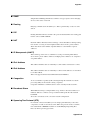
■■ An explanation of
R
and
N
notations used in charts
● Node notations
Explanation
Notation
R
Ring communication type
N
Non-ring communication type
● CB notations
Notation
RR
RN
NR
NN
Explanation
Chain connection : Ring communication type
Connection between chains : Ring communication type
Chain connection : Ring communication type
Connection between chains : Non-ring communication type
Chain connection : Non-ring communication type
Connection between chains : Ring communication type
Chain connection : Non-ring communication type
Connection between chains : Non-ring communication type
ii
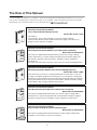
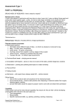
The Role of This Manual
A total of 6 different manuals are available for the Network Instrumentation Module. Read them as necessary for
your specific requirements. If a manual you require is not available, contact Yamatake Corporation or its dealer.
Alternatively, you can download the necessary manuals from “
”.
13
CP-SP-13
Network Instrumentation Module
User’s Manual Network Design Version
Manual No. CP-SP-1313E
Manual
User’s
Yamata
ke Co
rporat
ion
WARNING
N
CAUTIO
1313
CP-SP-
User’s
This Manual.
Personnel who are in charge of design of a network using the Network
Instrumentation Module should read this manual thoroughly. It describes how to
design a network and gives examples.
Manual
ING
WARN
ON
CAUTI
13
CP-SP-13
User’s
Yamata
Manual
ke Co
1313
CP-SP-
Manual
User’s
rporat
User’s
Manual
This manual is supplied with the NX-D15/25/35. Personnel in charge of design
and/or manufacture of a system using the NX-D15/25/35 should thoroughly read
this manual. It describes safety precautions, installation, wiring, and primary
specifications.
For further information about operation, refer to the user’s manual, Abridged Version.
Network Instrumentation Module
NX-D15/25 Controller Module User’s Manual Abridged Version
Manual No. CP-SP-1308E
This manual. Personnel who are using the NX-D15/25 for the first time or who are
in charge of hardware design and/or maintenance of a control panel containing the
NX-D15/25 should read this manual thoroughly. This manual describes the hardware,
surveys the NX-D15/25 and other products used with it, explains installation, wiring,
and troubleshooting, and gives hardware specifications.
ion
WARNING
N
CAUTIO
ING
WARN
ON
CAUTI
1313
CP-SP-
Network Instrumentation Module
NX-D15/25/35 Controller Module User’s Manual for Installation
Manual No. CP-UM-5561JE
WARNING
N
CAUTIO
ING
WARN
ON
CAUTI
Network Instrumentation Module
NX-CB1 Communication Box User’s Manual for Installation
Manual No. CP-UM-5558JE
This manual is supplied with the NX-CB1. Personnel in charge of design and/or
manufacture of a system using the NX-CB1 should read this manual thoroughly. It
describes safety precautions, installation, wiring, and primary specifications.
Network Instrumentation Module
Smart Loader Package SLP-NX Installation Guide
Manual No. CP-UM-5559JE
This manual is supplied with the SLP-NX Smart Loader Package and describes
installation of the software on a personal computer.
iii
13
CP-SP-13
User’s
Yamata
Manual
ke Co
rporat
ion
Network Instrumentation Module
Smart Loader Package SLP-NX User’s Manual
Manual No. CP-UM-5636E
This manual is included in the SLP-NX Smart Loader Package as a PDF file.
Personnel in charge of design or configuration of a system using the
Network Instrumentation Module should read this manual thoroughly.
The manual describes the software used to configure the Network
Instrumentation Module using a personal computer. It also describes
installation of the software on a personal computer, operation of the
personal computer, various functions, and setup procedures.
iv
Organization of This User's Manual
This manual is organized as follows:
Chapter 1 Overview
Provides an overview of the Network Instrumentation Module
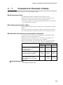
Chapter 2 Configuration of Ethernet Communications
Explains basic points and specific connection configurations for constructing an
Ethernet network.
Chapter 3 Configuration of Serial Communications
Explains basic points and specific connection configurations for constructing a
serial network.
Chapter 4 Network Function Design
Explains functional limits etc. for designing a network configuration with the
Network Instrumentation Modules.
Chapter 5 Function for Transmitting Data Between Modules
Explains functions for exchanging data between modules.
Appendix
A list of general terms used in this manual.
v
Contents
Conventions Used in This Manual
The Role of This Manual
Organization of This User's Manual
Chapter 1 Overview
1-1 Overview and Features. . . . . . . . . . . . . . . . . . . . . . . . . . . . . . . . . . . . . . . . . . . .
■■ Overview . . . . . . . . . . . . . . . . . . . . . . . . . . . . . . . . . . . . . . . . . . . . . . . . . . . .
■■ Features. . . . . . . . . . . . . . . . . . . . . . . . . . . . . . . . . . . . . . . . . . . . . . . . . . . . .
1-2 Model Numbers. . . . . . . . . . . . . . . . . . . . . . . . . . . . . . . . . . . . . . . . . . . . . . . . . .
1-3 Explanation of Module Features. . . . . . . . . . . . . . . . . . . . . . . . . . . . . . . . . . . .
■■ Controller module. . . . . . . . . . . . . . . . . . . . . . . . . . . . . . . . . . . . . . . . . . . . .
■■ Communication adapters. . . . . . . . . . . . . . . . . . . . . . . . . . . . . . . . . . . . . . .
■■ Terminal adapters. . . . . . . . . . . . . . . . . . . . . . . . . . . . . . . . . . . . . . . . . . . . .
■■ Cables . . . . . . . . . . . . . . . . . . . . . . . . . . . . . . . . . . . . . . . . . . . . . . . . . . . . . .
■■ Communication boxes. . . . . . . . . . . . . . . . . . . . . . . . . . . . . . . . . . . . . . . . .
1–1
1–1
1–1
1–2
1–3
1–3
1–4
1–4
1–4
1–5
Chapter 2 C
onfiguration of Ethernet Communications
2-1 Network Types. . . . . . . . . . . . . . . . . . . . . . . . . . . . . . . . . . . . . . . . . . . . . . . . . . . 2–2
■■ Ring communications/non-ring communications. . . . . . . . . . . . . . . . . . . 2–2
2-2 Model Number Selection . . . . . . . . . . . . . . . . . . . . . . . . . . . . . . . . . . . . . . . . . . 2–3
■■ Important points when Selecting the model number . . . . . . . . . . . . . . . . 2–3
2-3 Network Configuration. . . . . . . . . . . . . . . . . . . . . . . . . . . . . . . . . . . . . . . . . . . . 2–4
■■ Overview . . . . . . . . . . . . . . . . . . . . . . . . . . . . . . . . . . . . . . . . . . . . . . . . . . . . 2–4
■■ Basic network configuration . . . . . . . . . . . . . . . . . . . . . . . . . . . . . . . . . . . . 2–4
■■ Network configuration when using communication boxes . . . . . . . . . . . 2–5
2-4 Configuration Methods. . . . . . . . . . . . . . . . . . . . . . . . . . . . . . . . . . . . . . . . . . . . 2–6
■■ Chain connection : non-ring communications. . . . . . . . . . . . . . . . . . . . . . 2–6
■■ Chain connection: ring communications. . . . . . . . . . . . . . . . . . . . . . . . . . 2–8
■■ Connection between chains: non-ring communications . . . . . . . . . . . . 2–12
■■ Connection between chains: ring communications . . . . . . . . . . . . . . . . 2–14
■■ Long-range connections . . . . . . . . . . . . . . . . . . . . . . . . . . . . . . . . . . . . . . 2–16
2-5 Configuration With Other Devices. . . . . . . . . . . . . . . . . . . . . . . . . . . . . . . . . . 2–18
■■ SLP-NX. . . . . . . . . . . . . . . . . . . . . . . . . . . . . . . . . . . . . . . . . . . . . . . . . . . . . 2–18
■■ Host communications . . . . . . . . . . . . . . . . . . . . . . . . . . . . . . . . . . . . . . . . 2–22
2-6 Typical Wiring Examples and Prohibited . . . . . . . . . . . . . . . . . . . . . . . . . . . . 2–23
■■ Typical examples of wiring . . . . . . . . . . . . . . . . . . . . . . . . . . . . . . . . . . . . 2–23
■■ Example of wiring not permitted. . . . . . . . . . . . . . . . . . . . . . . . . . . . . . . . 2–26
2-7 Precautions for Placement of Cables. . . . . . . . . . . . . . . . . . . . . . . . . . . . . . . 2–29
■■ Minimum bend radius. . . . . . . . . . . . . . . . . . . . . . . . . . . . . . . . . . . . . . . . . 2–29
■■ Installing communication cables . . . . . . . . . . . . . . . . . . . . . . . . . . . . . . . 2–29
■■ Separation from sources of electromagnetic interference. . . . . . . . . . . 2–29
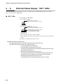
2-8 Ethernet Status Display ”NST” LEDs. . . . . . . . . . . . . . . . . . . . . . . . . . . . . . . 2–30
■■ “NST” LEDs. . . . . . . . . . . . . . . . . . . . . . . . . . . . . . . . . . . . . . . . . . . . . . . . . 2–30
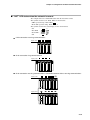
■■ “NST” LED status when the network is normal. . . . . . . . . . . . . . . . . . . . 2–31
■■ Example of “NST” LED status when there is an error on the network. . 2–34
vi
Chapter 3 Configuration of Serial Communications
3-1 Basic Configuration. . . . . . . . . . . . . . . . . . . . . . . . . . . . . . . . . . . . . . . . . . . . . .
3-2 Serial Communications Wiring . . . . . . . . . . . . . . . . . . . . . . . . . . . . . . . . . . . . .
■■ Wiring rules for serial communications. . . . . . . . . . . . . . . . . . . . . . . . . . .
■■ Example of wiring. . . . . . . . . . . . . . . . . . . . . . . . . . . . . . . . . . . . . . . . . . . . .
■■ When there are linked connections but you want to separate serial
communications. . . . . . . . . . . . . . . . . . . . . . . . . . . . . . . . . . . . . . . . . . . . . .
3-3 Configuration Methods. . . . . . . . . . . . . . . . . . . . . . . . . . . . . . . . . . . . . . . . . . . .
■■ Number of connected devices. . . . . . . . . . . . . . . . . . . . . . . . . . . . . . . . . . .
■■ Setting up device addresses. . . . . . . . . . . . . . . . . . . . . . . . . . . . . . . . . . . .
■■ Connecting to CMC (communication controller) series . . . . . . . . . . . . . .
3–2
3–3
3–3
3–3
3–4
3–5
3–5
3–5
3–6
Chapter 4 Network Function Design
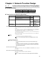
4-1 Functions and Connection Specifications of Participating Modules. . . . . . .
■■ Participating modules . . . . . . . . . . . . . . . . . . . . . . . . . . . . . . . . . . . . . . . . .
■■ Target functions and connection specifications. . . . . . . . . . . . . . . . . . . .
4-2 Connection Configuration. . . . . . . . . . . . . . . . . . . . . . . . . . . . . . . . . . . . . . . . .
4–1
4–1
4–1
4–2
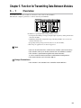
Chapter 5 Function for Transmitting Data Between Modules
5-1 Overview . . . . . . . . . . . . . . . . . . . . . . . . . . . . . . . . . . . . . . . . . . . . . . . . . . . . . . .
5-2 Functions. . . . . . . . . . . . . . . . . . . . . . . . . . . . . . . . . . . . . . . . . . . . . . . . . . . . . . .
■■ Function for transmitting data between modules.. . . . . . . . . . . . . . . . . . .
■■ Data flow . . . . . . . . . . . . . . . . . . . . . . . . . . . . . . . . . . . . . . . . . . . . . . . . . . . .
■■ Number of connected modules that can be used in this function. . . . . .
■■ Number of data that can be sent. . . . . . . . . . . . . . . . . . . . . . . . . . . . . . . . .
■■ Number of data records that can be received . . . . . . . . . . . . . . . . . . . . . .
■■ Setting through the SLP-NX. . . . . . . . . . . . . . . . . . . . . . . . . . . . . . . . . . . . .
■■ Supported functions. . . . . . . . . . . . . . . . . . . . . . . . . . . . . . . . . . . . . . . . . . .
■■ Error monitoring function . . . . . . . . . . . . . . . . . . . . . . . . . . . . . . . . . . . . . .
5–1
5–2
5–2
5–2
5–2
5–3
5–3
5–4
5–4
5–5
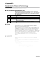
Appendix
Explanation of General Terminology. . . . . . . . . . . . . . . . . . . . . . . . . . . . . . .
■■ OSI (Open Systems Interconnection) Layer. . . . . . . . . . . . . . . . .
■■ Ethernet. . . . . . . . . . . . . . . . . . . . . . . . . . . . . . . . . . . . . . . . . . . . . .
■■ 100BASE-TX . . . . . . . . . . . . . . . . . . . . . . . . . . . . . . . . . . . . . . . . . .
■■ UTP (Unshielded Twist Pair) Cable . . . . . . . . . . . . . . . . . . . . . . . .
■■ STP (Shielded Twist Pair) Cable . . . . . . . . . . . . . . . . . . . . . . . . . .
■■ Bandwidth. . . . . . . . . . . . . . . . . . . . . . . . . . . . . . . . . . . . . . . . . . . .
■■ Node. . . . . . . . . . . . . . . . . . . . . . . . . . . . . . . . . . . . . . . . . . . . . . . . .
■■ Port. . . . . . . . . . . . . . . . . . . . . . . . . . . . . . . . . . . . . . . . . . . . . . . . . .
■■ Hub. . . . . . . . . . . . . . . . . . . . . . . . . . . . . . . . . . . . . . . . . . . . . . . . . .
■■ Switching Hub. . . . . . . . . . . . . . . . . . . . . . . . . . . . . . . . . . . . . . . . .
■■ Router . . . . . . . . . . . . . . . . . . . . . . . . . . . . . . . . . . . . . . . . . . . . . . .
vii
Appendix–1
Appendix–1
Appendix–1
Appendix–1
Appendix–2
Appendix–2
Appendix–2
Appendix–3
Appendix–3
Appendix–3
Appendix–3
Appendix–3
■■
■■
■■
■■
■■
■■
■■
■■
■■
■■
■■
■■
■■
■■
■■
■■
■■
■■
■■
■■
■■
■■
Topology . . . . . . . . . . . . . . . . . . . . . . . . . . . . . . . . . . . . . . . . . . . . .
Full Duplex. . . . . . . . . . . . . . . . . . . . . . . . . . . . . . . . . . . . . . . . . . . .
Half Duplex . . . . . . . . . . . . . . . . . . . . . . . . . . . . . . . . . . . . . . . . . . .
Auto Negotiation. . . . . . . . . . . . . . . . . . . . . . . . . . . . . . . . . . . . . . .
AutoMDI/MDI-X . . . . . . . . . . . . . . . . . . . . . . . . . . . . . . . . . . . . . . . .
MDI Wiring. . . . . . . . . . . . . . . . . . . . . . . . . . . . . . . . . . . . . . . . . . . .
MDI-X Wiring . . . . . . . . . . . . . . . . . . . . . . . . . . . . . . . . . . . . . . . . . .
Address . . . . . . . . . . . . . . . . . . . . . . . . . . . . . . . . . . . . . . . . . . . . . .
Unicast Transmission. . . . . . . . . . . . . . . . . . . . . . . . . . . . . . . . . . .
Multicast Transmission. . . . . . . . . . . . . . . . . . . . . . . . . . . . . . . . . .
Broadcast Transmission. . . . . . . . . . . . . . . . . . . . . . . . . . . . . . . . .
VLAN . . . . . . . . . . . . . . . . . . . . . . . . . . . . . . . . . . . . . . . . . . . . . . . .
SNMP . . . . . . . . . . . . . . . . . . . . . . . . . . . . . . . . . . . . . . . . . . . . . . . .
Routing . . . . . . . . . . . . . . . . . . . . . . . . . . . . . . . . . . . . . . . . . . . . . .
RIP . . . . . . . . . . . . . . . . . . . . . . . . . . . . . . . . . . . . . . . . . . . . . . . . . .
NAT . . . . . . . . . . . . . . . . . . . . . . . . . . . . . . . . . . . . . . . . . . . . . . . . .
IP Masquerade (=NAPT). . . . . . . . . . . . . . . . . . . . . . . . . . . . . . . . .
IPv4 Address. . . . . . . . . . . . . . . . . . . . . . . . . . . . . . . . . . . . . . . . . .
IPv6 Address. . . . . . . . . . . . . . . . . . . . . . . . . . . . . . . . . . . . . . . . . .
Congestion . . . . . . . . . . . . . . . . . . . . . . . . . . . . . . . . . . . . . . . . . . .
Broadcast Storm. . . . . . . . . . . . . . . . . . . . . . . . . . . . . . . . . . . . . . .
Spanning Tree Protocol (STP) . . . . . . . . . . . . . . . . . . . . . . . . . . . .
viii
Appendix–3
Appendix–5
Appendix–5
Appendix–5
Appendix–6
Appendix–6
Appendix–6
Appendix–6
Appendix–8
Appendix–8
Appendix–8
Appendix–8
Appendix–9
Appendix–9
Appendix–9
Appendix–9
Appendix–9
Appendix–9
Appendix–9
Appendix–9
Appendix–9
Appendix–9
Chapter 1 Overview
1 - 1
Overview and Features
■■ Overview
The Network Instrumentation Module uses Ethernet as standard to achieve
distributed instrumentation and high-speed communications, and reduce the
required wiring and engineering.
This gives customers the value of improved environments, quality and productivity.
■■ Features
●● Higher communication speed
• Ethernet equipped as standard
Each module is equipped with an Ethernet communication function.
When modules are connected or distributed, the use of a daisy chain connection
method greatly reduces the required wiring.
Each module is also equipped with an RS-485 communication function.
High-speed communications are possible to devices such as host systems,
programmable logic controllers (PLCs) and display devices.
The system can be upgraded to the Yamatake Monitor and Control System.
• Delivers full-scale distributed configuration
When connected by Ethernet, the system can be used with a distributed
configuration that has no functional differences from a connected configuration.
• Communication redundancy
Two communication configurations are available for the Ethernet network: nonring and ring.
• Linkages between modules make it possible to use input and output from other
modules.
●● Engineering tools
Smart Loader Package SLP-NX is available (sold separately).
The Ethernet connection enables simultaneous connection to multiple modules.
This provides centralized management, setting and monitoring, which
contributes to reduced engineering requirements.
1–1
Chapter 1 Overview
1 - 2
Model Numbers
This manual applies to the following model numbers. These model numbers are simply called “modules” from here
on.
Model No.
NX-D15______
Controller Module D15
NX-D25______
Controller Module D25
NX-CB1__04__
Communication Box
NX-C_1000000
Communication Adapter
NX-T_1000000
Terminal Adapter
NX-DX_______
1–2
Name
Chapter 1 Overview
1 - 3
Explanation of Module Features
This section explains module features.
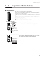
■■ Controller module
PWR RUN
MOD COM
NST
Side connectors are located on the both side of the base.
A daisy chain connection for Ethernet communications or for serial communications by
using side connectors to link each module.
A UTP cable can be connected by linking a communication adapter or a communication
box.
To choose chain connection ring communications or non-ring communications via
Ethernet, refer to model numbers.
For details on model number selection,
Section 2-2, Model Number Selection (Page 2-3).
FAIL
F0
F1
F9
F5
NX-D25N
LOCK
2
5
6
CONNECT
1
4
Communication
status.
(default setting)
CONNECT
CONNECT
●● RS-485 cutoff switch
Enlarged view
Non-communication
status
The RS-485 cutoff switch is located on the base.
It is used to disconnect communications from the right module.
●● RS-485 communication terminals
There are RS-485 communication terminals (3-wire) on the base.Use
these communication terminals for serial communications.
1
4
RS-485 communication
terminal:
A 3-wire system
RS-485 communication
terminal.
2
5
6
No.
4
5
6
Signal
DA
DB
SG
1–3
Chapter 1 Overview
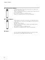
■■ Communication adapters
A communication adapter is connected to a side connecter of a module so that a
UTP cable connection is possible.
Adapters for the right side and left side are available to support module’s both side
connectors (right and left).
These adapters do not function as communication nodes.
Adapters are not included in the devices used for power supply design.
■■ Terminal adapters
RING
Terminal adapters are connected to a side connector of a module and are used as
a chain connection ring communication terminal (Ethernet communication path
inside the base).
UTP cables cannot be connected.
Adapters for the right side and left side are available to support module’s both side
connectors (right and left).
These adapters do not function as communication nodes.
The adapters are not included in the devices used for power supply design.
■■ Cables
Use 4-pair straight wire UTP (unshielded twisted pair) Cat 5E cable or higher.
These modules do not support STP (shielded twisted pair) cable.
1–4
Chapter 1 Overview
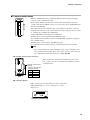
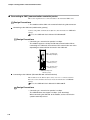
■■ Communication boxes
PWR RUN
MOD COM
NST
Ethernet communications are possible through the (four) front ports and right
connecter of the communication box.
The box that is linked to the left side of chain-connected modules is used for a
cascade connection of multiple chains or as connection ports for multiple Ethernet
devices or the SLP-NX.
Since ring and non-ring communications are possible for both chain connection
(using the side connector) and connection between chains (using front ports 3 and
4), 4 models are available in all combinations.
Connect UTP cables to the front ports as shown below
<Ethernet ports 1 and 2> (general-purpose Ethernet ports)
For communications with the host device or the SLP-NX, regardless of ring/nonring communications
<Ethernet ports 3 and 4> (daisy chain Ethernet ports)
For connection between chains. Connect communication boxes to each other.
FAIL
NST
LINK
/ ACT
1
2
3
4
NX-CB1N
1
2
3
4
Note
• The connection between chains in Ethernet ports 3 and 4 is limited to nonring communications models. These ports can be used as a connection port
for communications with the host device and the SLP-NX.
●● RS-485 communication terminals
here are RS-485 communication terminals (3-wire) on the
T
base. (3-wire). Use these communication terminals for serial
communications.
RS-485 communication
terminal:
RS-485 communication
terminals (3-wire).
1
4
2
5
6
No.
4
5
6
Signal
DA
DB
SG
●● Operation display
LEDs on the front of the box indicate the state of operation.
LEDs blink fast (0.2 sec. cycle) or slow(1.4 sec. cycle).
Display area:
PWR RUN
MOD COM
NST
FAIL
NST
LINK
/ ACT
1
2
3
4
NX-CB1N
1–5
Chapter 1 Overview
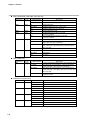
●● PWR, RUN, MOD, COM, NST, FAIL (top row)
LED name
PWR
RUN
Color
Green
Green
Lighting pattern
Lit
Description
Power ON (energized)
Off
Power OFF (not energized)
Lit
Normal operation
Slow blink
Hardware failure (errors in some ports)
Off
Hardware failure (errors in all ports)
MOD
Orange
Off
Normal operation mode
COM
Green
Lit
Sending Ethernet packets to the side
connector network
Not sending Ethernet packets to the side
connector network
Chain connection is non-ring communications
Off
NST
Orange
Lit
Fast blink
Off
The ring is disconnected in the chain connection (the
ring is disconnected somewhere)
The ring is disconnected in the chain connection (the
ring connection to the main node or the next node is
disconnected)
Ring communication for the chain connection is normal
Lit
Hard Failure
Slow blink
Soft Failure
Off
No errors
Lighting pattern
Lit
Description
Connection between chains is non-ring communication
Fast blink
The ring is disconnected in the connection between
chains (the ring is disconnected somewhere)
The ring is disconnected in the connection between
chains (the ring connecting to this CB or the next CB is
disconnected)
Slow blink
FAIL
Red
●● NST (middle row)
LED name
NST
Color
Orange
Slow blink
Off
Ring communication for the connection between
chains is normal
●● LINK/ACT1-4 (bottom row)
LED name
LINK/ACT1
LINK/ACT2
LINK/ACT3
LINK/ACT4
1–6
Color
Orange
Orange
Orange
Orange
Lighting pattern
Lit
Port 1 is linked
Description
Flashing
Port 1 Ethernet packet send/receive in progress
Off
Port 1 is not linked
Lit
Port 2 is linked
Flashing
Port 2 Ethernet packet send/receive in progress
Off
Port 2 is not linked
Lit
Port 3 is linked
Flashing
Port 3 Ethernet packet send/receive in progress
Off
Port 3 is not linked
Lit
Port 4 is linked
Flashing
Off
Port 4 Ethernet packet send/receive in progress
Port 4 is not linked
Chapter 1 Overview
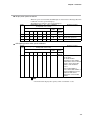
●● Display when power turned ON
When the power is turned ON, the LEDs light as shown in the following table. This
is different from the operation displays.
The LEDs then transition to the operation displays.
Order
LED lighting state (: Lit, −: Off, : Blinking,
✽: Depends on the state)
Top LEDs
Middle
Bottom
LEDs
LEDs
PWR RUN MOD COM NST FAIL
NST
LINK/
ACT1-4
State/Processing
1
−
−
−
−
−
−
−
−
Power-off
2
✽
✽
✽
✽
✽
✽
✽
Shortly after power-on
3
✽
✽
✽
Operation display
●● LED lighting pattern under special conditions
Priority
Level
LED lighting state (:Lit, −:Off,:Slow blink, :Fast blink,
✽:Depends on the state)
Top LEDs
Middle
Bottom
LEDs
LEDs
PWR RUN MOD COM NST FAIL
NST
LINK/
ACT1-4
✽
✽
✽
✽
State/Processing
A wrong module is inserted
into the base.
The model number
information for the module
and the base does not match.
Check to see if the model
number of the module is
correct.
If the model number is
correct, the model number of
the base might be incorrect.
Replace it with a base
that has the correct model
number.
Note
• The hard failure display takes priority when a hard failure occurs.
1–7
Chapter 1 Overview
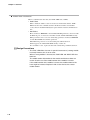
●● Actions when a fault occurs
When a communication box fails, the “FAIL” LED is lit or blinks.
• Hard Failure
When a hardware failure occurs it is treated as a hard failure and the “FAIL”
LED is lit. Since the communication box breaks down when a hard failure
occurs, the box should immediately be replaced with a notmal communication
box.
• Soft Failure
Errors in the base EEPROM or the main Flash ROM parameters, and errors with
the Ethernet port, are treated as soft failure and the “FAIL” LED blinks slowly.
When parameter errors occur, use functioning parameters in the base EEPROM
or main Flash ROM and continue operations.
When Ethernet port errors occur, the failed ports will not function.
If this happens, the “RUN” LED blinks slowly or turns off.
If a soft failure occurs, replace the box with a functioning communication box.
Design Precautions
• The “FAIL” LED blinks fast even in special circumstance (a wrong module
inserted). However, this is not an error.
When a wrong module is inserted, the “RUN” LED and “MOD” LED also
blink fast.
The model number information for the module and the base does not
match. Check to see if the model number of the module is correct.
If the model number of the module is correct, the model number of the
base might be incorrect. Replace it with a base that has the correct
model number.
1–8
Chapter 2 Configuration of Ethernet
Communications
This chapter describes the configuration of Ethernet communications for modules, including basic points, model
number selection, and specific connection configurations.
2–1
Chapter 2 Configuration of Ethernet Communications
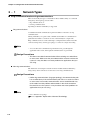
2 - 1
Network Types
■■ Ring communications/non-ring communications
There are basically two types of networks for these modules. They are connected
using daisy chain topology, and are either:
•ring communications, or
•non-ring communications
depending on whether redundancy is supported.
●● Ring communications
A redundant network communication path for modules is referred to as ring
communications.
Having redundancy on a path avoids communication failures in communication
paths that have failed as a result of an error or abnormality in a single node.
Ring communications are achieved through a configuration that allows networks
connected using a daisy chain-type topology to connect in a single closed ring.
Note
• A reverse direction communication path that does not pass through the
applicable node is used, and loopback communications are performed.
Design Precautions
• This does not avoid all communication failures relating to a node failure
or error status. Make sure that you understand the structure and use the
system in a way that does not create problems for applications that you
are using.
●● Non-ring communications
The method of connecting the network for these modules without redundancy,
using a daisy chain connection, is referred to as non-ring communications.
Design Precautions
• Unlike ring communications (ring-type topology), the communication path
has no redundancy. If the communication path fails as a result of a failure
or error status in one node, communications are not established for any
of the nodes from the problem node onwards in the chain connection.
Be careful to use the system in a way that does not create problems for
applications that you are using.
Note
• For a definition of topology,
refer to Appendix - Explanation of General Terminology.
2–2
Chapter 2 Configuration of Ethernet Communications
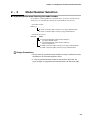
2 - 2
Model Number Selection
■■ Important points when Selecting the model number
If you will be conducting Ethernet communications, specify the desired network
functions for each module by selecting the model numbers shown below.
•Controller module:
NX-D_5 _ _ _ _ _ _
N: Chain connection (side connector), non-ring communications
R: Chain connection (side connector), ring communications
•Communication boxes
NX-CB1 _ _ 0400
N: Connection between chains (front panel port),
non-ring communications
R: Connection between chains (front panel port),
ring communications
N: Chain connection (side connector), non-ring communications
R: Chain connection (side connector), ring communications
Design Precautions
• Ring and non-ring communication modules cannot be combined in chain
connection or in connection between chains.
• If a non-ring communication module is connected in ring mode, the
status changes to congested and communications will not be possible.
2–3
Chapter 2 Configuration of Ethernet Communications
2 - 3
Network Configuration
■■ Overview
This section explains the basic patterns for configuring Ethernet communications.
For details,
refer to Section 2-4, Configuration Methods (Page 2-6).
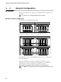
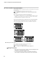
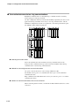
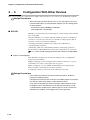
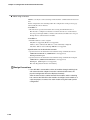
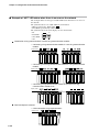
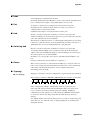
■■ Basic network configuration
The network is configured by linking modules.
Non-ring
PWR RUN
MOD COM
NST
N
F1
PWR RUN
FAIL
NST
N
F1
F9
F5
NX-D35N
MOD COM
PWR RUN
FAIL
Ring
NST
N
F1
F9
F5
NX-D35N
MOD COM
PWR RUN
FAIL
NST
N
F1
F9
F5
NX-D35N
MOD COM
PWR RUN
FAIL
F9
F5
F1
RING
NX-D35N
MOD COM
NST
R
F9
F5
PWR RUN
FAIL
F1
NX-D35N
MOD COM
NST
R
F9
F5
PWR RUN
FAIL
F1
NX-D35N
MOD COM
NST
R
F9
F5
PWR RUN
FAIL
F1
NX-D35N
MOD COM
NST
R
F9
F5
FAIL
RING
NX-D35N
T
A
LOCK
LOCK
LOCK
T
A
LOCK
LOCK
LOCK
LOCK
LOCK
A distributed configuration can be achieved using a Ethernet cable.
Non-ring
PWR RUN
MOD COM
NST
N
F1
FAIL
NX-D35N
MOD COM
NST
N
F1
F9
F5
PWR RUN
FAIL
NX-D35N
MOD COM
NST
N
F1
F9
F5
PWR RUN
FAIL
NX-D35N
MOD COM
NST
N
F1
F9
F5
PWR RUN
PWR RUN
FAIL
LOCK
LOCK
NST
FAIL
PWR RUN
MOD COM
NST
N
F1
F9
F5
NX-D35N
C
A
LOCK
MOD COM
N
F1
F9
F5
NX-D35N
FAIL
PWR RUN
MOD COM
NST
N
F1
F9
F5
NX-D35N
FAIL
PWR RUN
MOD COM
NST
N
F1
F9
F5
NX-D35N
FAIL
F9
F5
NX-D35N
C
A
LOCK
LOCK
LOCK
LOCK
LOCK
Ring
PWR RUN
RING
F1
MOD COM
F5
R
NST
F9
NX-D35N
FAIL
PWR RUN
F1
MOD COM
F5
R
NST
F9
NX-D35N
FAIL
PWR RUN
F1
MOD COM
F5
R
NST
F9
NX-D35N
FAIL
PWR RUN
F1
MOD COM
F5
R
NST
PWR RUN
FAIL
F1
F9
NX-D35N
T
A
C
A
LOCK
LOCK
LOCK
LOCK
MOD COM
F5
R
NST
F9
NX-D35N
FAIL
PWR RUN
F1
MOD COM
F5
R
NST
F9
NX-D35N
FAIL
PWR RUN
F1
MOD COM
F5
R
NST
F9
NX-D35N
FAIL
PWR RUN
F1
MOD COM
F5
R
NST
F9
NX-D35N
C
A
FAIL
RING
T
A
LOCK
LOCK
LOCK
LOCK
Even if modules are connected using Ethernet cables, they are recognized as one
chain in the SLP-NX
This type of distributed configuration is suitable when modules are located
relatively close together, for example, in the same platform or a neighboring
platform (with a connecting cable that is less than 50 m in length).
For network configurations with the modules in separate locations,
refer to ■ Network configuration when using communication boxes (next
page).
2–4
Chapter 2 Configuration of Ethernet Communications
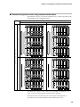
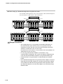
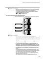
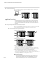
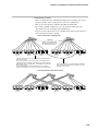
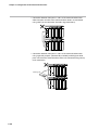
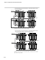
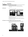
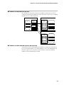
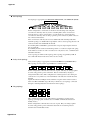
■■ Network configuration when using communication boxes
The following four types of network configurations are possible, depending on the
model number of the communication box.
Chain connection
Ring
PWR RUN
NX-CB1N
RR
MOD COM
R
F1
F5
NST
FAIL
PWR RUN
MOD COM
R
F1
F9
NX-D35N
Non-ring
F5
NST
FAIL
PWR RUN
MOD COM
R
F1
F9
NX-D35N
F5
NST
FAIL
PWR RUN
MOD COM
R
F1
F9
NX-D35N
F5
NST
FAIL
PWR RUN
F9
NX-D35N
NX-CB1N
NR
1
2
C
B
T
A
2
3
3
4
4
LOCK
RR
F1
MOD COM
NST
R
F9
F5
LOCK
FAIL
PWR RUN
F1
NX-D35N
MOD COM
NST
R
F9
F5
LOCK
FAIL
PWR RUN
R
F1
NX-D35N
MOD COM
F5
NST
PWR RUN
R
F1
F9
NX-D35N
MOD COM
F5
NST
PWR RUN
RING
F9
NX-D35N
NX-CB1N
NR
Ring
2
3
3
4
LOCK
RR
MOD COM
R
F1
F5
NST
LOCK
FAIL
PWR RUN
R
F1
F9
NX-D35N
MOD COM
F5
NST
LOCK
FAIL
PWR RUN
R
F1
F9
NX-D35N
MOD COM
F5
NST
PWR RUN
R
F1
F9
NX-D35N
MOD COM
F5
NST
NX-CB1N
NST
FAIL
PWR RUN
MOD COM
N
F1
F9
F5
NST
FAIL
PWR RUN
MOD COM
N
F1
F9
NX-D35N
F5
NST
FAIL
F9
NX-D35N
LOCK
FAIL
PWR RUN
N
F1
F9
MOD COM
F5
NST
LOCK
FAIL
PWR RUN
N
F1
F9
NX-D35N
MOD COM
F5
NST
LOCK
FAIL
PWR RUN
N
F1
F9
NX-D35N
MOD COM
F5
NST
FAIL
F9
NX-D35N
C
B
NR
Connection between chains
T
A
2
3
4
RN
MOD COM
NST
LOCK
FAIL
PWR RUN
R
MOD COM
NST
LOCK
MOD COM
N
F1
F5
NST
LOCK
FAIL
PWR RUN
MOD COM
N
F1
F9
NX-D35N
F5
NST
LOCK
FAIL
PWR RUN
N
F1
F9
NX-D35N
MOD COM
F5
NST
LOCK
FAIL
PWR RUN
N
F1
F9
NX-D35N
MOD COM
F5
NST
FAIL
F9
NX-D35N
FAIL
PWR RUN
R
NX-D35N
MOD COM
NST
FAIL
PWR RUN
R
NX-D35N
C
B
LOCK
MOD COM
NST
LOCK
PWR RUN
FAIL
R
NX-D35N
NX-CB1N
NX-D35N
NN
MOD COM
N
F1
F5
NST
LOCK
FAIL
F9
PWR RUN
MOD COM
N
F1
NX-D35N
F5
NST
LOCK
FAIL
F9
PWR RUN
MOD COM
N
F1
NX-D35N
F5
NST
LOCK
FAIL
F9
PWR RUN
MOD COM
N
F1
NX-D35N
F5
NST
FAIL
F9
NX-D35N
1
1
C
B
T
A
2
3
3
4
4
LOCK
PWR RUN
RN
F1
MOD COM
NST
R
F9
F5
LOCK
FAIL
PWR RUN
F1
NX-D35N
MOD COM
NST
R
F9
F5
LOCK
FAIL
PWR RUN
F1
NX-D35N
MOD COM
NST
R
F9
F5
C
B
LOCK
LOCK
FAIL
PWR RUN
R
F1
NX-D35N
MOD COM
F5
NST
PWR RUN
FAIL
RING
F9
NX-D35N
NX-CB1N
NN
MOD COM
N
F1
F5
NST
LOCK
FAIL
PWR RUN
N
F1
F9
NX-D35N
MOD COM
F5
NST
LOCK
FAIL
PWR RUN
N
F1
F9
NX-D35N
MOD COM
F5
NST
LOCK
FAIL
PWR RUN
N
F1
F9
NX-D35N
MOD COM
F5
NST
FAIL
F9
NX-D35N
Non-ring
1
1
C
B
T
A
2
3
3
4
4
LOCK
PWR RUN
RN
F1
MOD COM
R
F5
NST
F9
NX-D35N
LOCK
FAIL
PWR RUN
F1
MOD COM
R
F5
NST
F9
NX-D35N
LOCK
FAIL
PWR RUN
F1
MOD COM
R
F5
NST
F9
NX-D35N
C
B
LOCK
LOCK
FAIL
PWR RUN
F1
MOD COM
R
F5
NST
PWR RUN
FAIL
F9
NX-CB1N
NX-D35N
NN
F1
MOD COM
N
F5
NST
F9
NX-D35N
LOCK
FAIL
PWR RUN
F1
MOD COM
N
F5
NST
F9
NX-D35N
LOCK
FAIL
PWR RUN
F1
MOD COM
N
F5
NST
F9
NX-D35N
LOCK
FAIL
PWR RUN
F1
MOD COM
N
F5
NST
FAIL
F9
NX-D35N
1
1
2
F5
NST
NX-D35N
NR
F9
NX-D35N
C
B
PWR RUN
NX-CB1N
N
F1
PWR RUN
3
2
F5
NX-D35N
1
LOCK
NX-CB1N
MOD COM
N
F1
LOCK
FAIL
4
2
MOD COM
LOCK
FAIL
1
NX-CB1N
PWR RUN
1
T
A
4
2
FAIL
F9
LOCK
FAIL
C
B
PWR RUN
NX-CB1N
NST
C
B
LOCK
FAIL
1
2
F5
NX-D35N
1
PWR RUN
NX-CB1N
MOD COM
N
F1
C
B
T
A
2
3
3
4
4
LOCK
LOCK
LOCK
LOCK
C
B
LOCK
LOCK
LOCK
LOCK
Communication adapters can be used to set up a distributed configuration for
chain connections (the horizontal connections in this diagram).
Connections between chains (the vertical connections in this diagram) are
performed when connecting modules located in different locations.
2–5
Chapter 2 Configuration of Ethernet Communications
2 - 4
Configuration Methods
This section explains how to configure Ethernet communications. The following five types of configurations are
possible:
••Chain connection: non-ring communications
••Chain connection: ring communications
••Connection between chains : non-ring communications
••Connection between chains : ring communications
••Long-range connection
The details of each type are explained below.
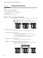
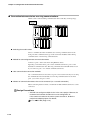
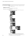
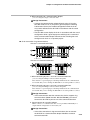
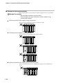
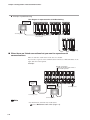
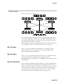
■■ Chain connection : non-ring communications
Basically, this type of connection is built using daisy chain topology without using
a hub.
For network configurations with nodes in separate locations,
refer to ■ Network configuration when using communication boxes
(previous page).
PWR RUN
F1
MOD COM
NST
FAIL
PWR RUN
F1
F9
F5
NX-D25N
MOD COM
NST
FAIL
PWR RUN
F1
F9
F5
NX-D25N
MOD COM
NST
PWR RUN
FAIL
F1
F9
F5
NX-D25N
LOCK
NST
FAIL
PWR RUN
F1
F9
F5
MOD COM
NST
FAIL
PWR RUN
F1
F9
F5
NX-D25N
MOD COM
NST
PWR RUN
FAIL
F1
F9
F5
NX-D25N
LOCK
LOCK
NST
FAIL
PWR RUN
F1
F9
F5
MOD COM
NST
FAIL
PWR RUN
F1
F9
F5
MOD COM
NST
FAIL
F9
F5
NX-D25N
NX-D25N
C
A
C
A
LOCK
MOD COM
NX-D25N
C
A
C
A
LOCK
MOD COM
NX-D25N
LOCK
LOCK
LOCK
LOCK
●● Selecting the model number
Use the non-ring communication model number for all nodes being used.
●● Forming connections between nodes
The following two methods can be used for connections between nodes:
•connect the modules by linking them
•use a communication adapter and connect the nodes with an Ethernet cable
You can also use a combination of these connections methods.
●● Number of nodes that can be connected
A maximum of 31 nodes can be connected in a single chain.
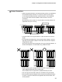
●● When setting up a distributed configuration using Ethernet cables,
the maximum cable length that can be used is 50 meters. The maximum length for the
total amount of cable used in a chain is 80 meters.
Total cable length: 80 m max.
50m max.
PWR RUN
F1
MOD COM
F5
NST
F9
NX-D25N
FAIL
PWR RUN
F1
MOD COM
F5
NST
F9
NX-D25N
FAIL
PWR RUN
F1
MOD COM
F5
NST
PWR RUN
FAIL
F1
F9
NX-D25N
2–6
LOCK
MOD COM
F5
NST
F9
NX-D25N
C
A
LOCK
50m max.
LOCK
FAIL
PWR RUN
F1
MOD COM
F5
NST
F9
NX-D25N
FAIL
PWR RUN
F1
MOD COM
F5
NST
PWR RUN
FAIL
F1
F9
NX-D25N
C
A
C
A
LOCK
LOCK
MOD COM
F5
NST
F9
NX-D25N
LOCK
FAIL
PWR RUN
F1
MOD COM
F5
NST
F9
NX-D25N
FAIL
PWR RUN
F1
MOD COM
F5
NST
F9
NX-D25N
C
A
LOCK
LOCK
LOCK
FAIL
Chapter 2 Configuration of Ethernet Communications
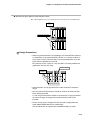
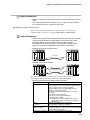
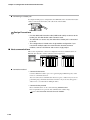
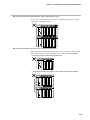
Design Precautions
• Unlike ring communications, the communication path has no redundancy.
If the communication path fails as a result of a failure or error status
in one node (including no power), communications is not established
for any of the nodes from the problem node onwards in the chain
connection.
Be careful to use the system in a way that does not create problems for
applications that you are using.
Error occurrence
Host communications
PWR RUN
F1
MOD COM
NST
PWR RUN
FAIL
F1
F9
F5
NX-D25N
MOD COM
F5
NST
F9
NX-D25N
FAIL
PWR RUN
F1
MOD COM
F5
NST
PWR RUN
FAIL
F1
F9
NX-D25N
C
A
C
A
LOCK
LOCK
MOD COM
NST
PWR RUN
FAIL
F1
F9
F5
NX-D25N
MOD COM
NST
PWR RUN
FAIL
F1
F9
F5
NX-D25N
MOD COM
NST
PWR RUN
FAIL
C
A
LOCK
NST
PWR RUN
FAIL
LOCK
MOD COM
F1
F9
F5
NX-D25N
C
A
LOCK
MOD COM
F1
F9
F5
NX-D25N
NST
PWR RUN
FAIL
MOD COM
F1
F9
F5
NX-D25N
NST
FAIL
F9
F5
NX-D25N
C
A
LOCK
LOCK
LOCK
LOCK
Communication range
• Communications are not guaranteed if a cable exceeds the maximum
length.
• For a distributed configuration using communication adapters, connect
right-side communication adapters to left-side communication adapters
using Ethernet cables.
We cannot guarantee correct operations when two right-side adapters, or
two left-side adapters, are connected using a Ethernet cable.
PWR RUN
F1
MOD COM
NST
FAIL
PWR RUN
F1
F9
F5
NX-D25N
MOD COM
NST
FAIL
PWR RUN
F1
F9
F5
NX-D25N
MOD COM
NST
PWR RUN
FAIL
F1
F9
F5
NX-D25N
C
A
LOCK
PWR RUN
F1
MOD COM
F5
NST
F9
NX-D25N
LOCK
FAIL
PWR RUN
F1
MOD COM
F5
NST
F9
NX-D25N
FAIL
PWR RUN
F1
MOD COM
F5
FAIL
PWR RUN
F1
NST
NST
FAIL
PWR RUN
F1
F9
F5
MOD COM
NST
FAIL
F9
F5
PWR RUN
F1
NX-D25N
MOD COM
F5
NST
FAIL
PWR RUN
F1
F9
NX-D25N
MOD COM
NST
FAIL
PWR RUN
F1
F9
F5
NX-D25N
MOD COM
NST
FAIL
F9
F5
NX-D25N
C
A
LOCK
PWR RUN
FAIL
F1
F9
MOD COM
F5
NST
F9
NX-D25N
LOCK
MOD COM
NX-D25N
C
A
NX-D25N
LOCK
NST
F9
F5
LOCK
C
A
LOCK
MOD COM
NX-D25N
LOCK
FAIL
PWR RUN
F1
MOD COM
F5
NST
F9
NX-D25N
LOCK
FAIL
PWR RUN
F1
MOD COM
F5
NST
LOCK
FAIL
LOCK
PWR RUN
F9
F1
NX-D25N
MOD COM
F5
NST
F9
NX-D25N
C
A
FAIL
LOCK
PWR RUN
F1
MOD COM
F5
NST
F9
NX-D25N
FAIL
PWR RUN
F1
MOD COM
NST
FAIL
F9
F5
NX-D25N
C
A
LOCK
LOCK
LOCK
LOCK
LOCK
LOCK
• Please use 4P (4-pair) straight wire UTP (Cat 5E or higher) Ethernet
cable (ANSI/TIA/EIA-568-B wire at both ends).
These modules do not support STP (shielded twisted pair) cable.
• Use non-ring communication nodes for all modules being connected.
• Do not connect terminal adapters when using non-ring communications.
If you do so, the path will become congested and communications will
not be possible.
2–7
Chapter 2 Configuration of Ethernet Communications
■■ Chain connection: ring communications
You can build a redundant communication path by connecting daisy chain topology
to ring topology.
For network configurations with nodes in separate locations,
refer to ■ Network configuration when using communication boxes
(Page 2-5).
This connection method has the following design limitations:
•In a distributed configuration, there is one physical Ethernet cable so it is not a
redundant control system because the cable can be removed or disconnected.
•A communication box is required to connect to a PC.
Your selection should be based on considerations such as the network reliability
required for the devices and applications that you are using, and the distance
between the distributed modules when setting up a distributed configuration.
PWR RUN
RING
F1
MOD COM
NST
R
F9
F5
PWR RUN
FAIL
F1
NX-D35N
MOD COM
NST
R
F9
F5
PWR RUN
FAIL
F1
NX-D35N
MOD COM
NST
R
F9
F5
PWR RUN
FAIL
F1
NX-D35N
MOD COM
NST
R
F9
F5
FAIL
RING
NX-D35N
T
A
T
A
LOCK
LOCK
PWR RUN
NX-CB1N
RR
MOD COM
NST
R
F1
F5
FAIL
LOCK
PWR RUN
MOD COM
R
F1
F9
NX-D35N
F5
NST
FAIL
LOCK
MOD COM
PWR RUN
F1
F9
NX-D35N
R
F5
NST
FAIL
PWR RUN
F1
F9
NX-D35N
MOD COM
R
F5
NST
F9
NX-D35N
FAIL
RING
1
2
C
B
T
A
3
4
LOCK
PWR RUN
RING
F1
MOD COM
F5
R
NST
FAIL
F9
NX-D35N
PWR RUN
F1
MOD COM
F5
R
LOCK
NST
F9
NX-D35N
FAIL
PWR RUN
F1
MOD COM
F5
R
LOCK
NST
F9
NX-D35N
FAIL
PWR RUN
F1
MOD COM
F5
R
LOCK
NST
PWR RUN
FAIL
F1
F9
NX-D35N
T
A
C
A
LOCK
LOCK
LOCK
LOCK
MOD COM
F5
R
NST
F9
NX-D35N
FAIL
PWR RUN
F1
MOD COM
F5
R
NST
F9
NX-D35N
FAIL
PWR RUN
F1
MOD COM
F5
R
NST
F9
NX-D35N
FAIL
PWR RUN
F1
MOD COM
F5
R
NST
F9
NX-D35N
C
A
FAIL
RING
T
A
LOCK
LOCK
LOCK
LOCK
●● Selecting the model number
Ring communication modules should be used for all nodes.
For information on selecting model numbers,
refer to Section 2-2, Model Number Selection (Page 2-3).
Design Precautions
• Ring and non-ring communication modules cannot be combined in chain
connection or in connection between chains.
• If a non-ring communication module is connected in ring mode, the
status changes to congested and communication will not be possible.
2–8
Chapter 2 Configuration of Ethernet Communications
●● Forming connections between nodes
The following two methods can be used for connections between nodes:
•Linking modules
•Using communication adapters and Ethernet cables to connect modules
You can also use these methods together.
●● Configuring ring communications
Ring communications can be configured in the following two ways:
•Connecting terminal adapters at both ends of the chain
•Connecting a communication box at the left end of the chain and a terminal
adapter at the right end of the chain
When terminal adapters are connected to both ends, there are no ports available to
connect an Ethernet cable. Use the loader jack of a module and configure settings.
Host communications are conducted via RS-485.
When using the SLP-NX or executing host communications via Ethernet, place a
communication box at the left end. Connect a terminal adapter at the right end.
●● Host communication connection methods
Use a communication box and connect to ports 1 and 2 at the front. If you are using
the communication box model that uses non-ring communications for the front
ports, you can also use ports 3 and 4.
●● Number of nodes that can be connected
A maximum of 31 nodes can be connected in a single chain.
2–9
Chapter 2 Configuration of Ethernet Communications
●● When setting up a distributed configuration using Ethernet cables,
the maximum cable length that can be used is 50 meters. The maximum length for
the total amount of cable used in a chain is 80 meters.
Total cable length: 80 m max.
50m max.
PWR RUN
RING
MOD COM
NST
R
F0
FAIL
PWR RUN
NX-D35N
MOD COM
NST
R
F0
FAIL
PWR RUN
MOD COM
R
NX-D25N
NST
FAIL
PWR RUN
MOD COM
R
F0
NX-D25N
NST
PWR RUN
FAIL
F1
LOCK
F5
NST
FAIL
PWR RUN
MOD COM
R
F1
F9
NX-D35N
C
A
LOCK
MOD COM
R
F0
NX-D25N
T
A
LOCK
50m max.
F5
NST
FAIL
PWR RUN
MOD COM
R
F1
F9
NX-D25N
F5
NST
FAIL
PWR RUN
MOD COM
R
F1
F9
NX-D25N
F5
NST
PWR RUN
FAIL
C
A
LOCK
LOCK
LOCK
F5
NST
FAIL
PWR RUN
MOD COM
R
F1
F9
NX-D35N
C
A
LOCK
MOD COM
R
F1
F9
NX-D25N
F5
NST
FAIL
PWR RUN
MOD COM
R
F1
F9
NX-D25N
F5
NST
FAIL
PWR RUN
MOD COM
R
F1
F9
NX-D25N
F5
NST
FAIL
F9
RING
NX-D25N
T
A
C
A
LOCK
LOCK
LOCK
LOCK
LOCK
Total cable length: 80 m max.
50m max.
PWR RUN
NX-CB1N
RR
F1
MOD COM
R
F5
NST
F9
NX-D35N
FAIL
PWR RUN
F1
MOD COM
R
F5
NST
F9
NX-D25N
FAIL
PWR RUN
F1
MOD COM
R
F5
NST
F9
NX-D25N
FAIL
PWR RUN
F1
MOD COM
R
F5
NST
50m max.
PWR RUN
FAIL
MOD COM
NST
R
F9
NX-D35N
NX-D25N
FAIL
PWR RUN
MOD COM
NST
R
NX-D25N
FAIL
PWR RUN
MOD COM
NST
R
NX-D25N
FAIL
PWR RUN
MOD COM
NST
PWR RUN
FAIL
R
F1
NX-D25N
MOD COM
R
F5
NST
F9
NX-D35N
FAIL
PWR RUN
F1
MOD COM
R
F5
NST
F9
NX-D25N
FAIL
PWR RUN
F1
MOD COM
R
F5
NST
F9
NX-D25N
FAIL
PWR RUN
F1
MOD COM
R
F5
NST
F9
NX-D25N
FAIL
RING
1
2
C
A
C
B
C
A
C
A
T
A
C
A
3
4
LOCK
LOCK
LOCK
LOCK
LOCK
LOCK
LOCK
LOCK
LOCK
LOCK
LOCK
LOCK
Design Precautions
• This configuration uses a ring network and provides redundancy in
the communication path. However, there is no guarantee that the
redundancy function will work or that the communication path will be
effective if a node fails or has an error status.
Be careful to use the system in a way that does not create problems for
applications that you are using.
• If a non-ring communication module is connected in a ring
communication configuration, the system may become congested and
crash. All connected modules should be a ring communication type.
• Communication is not guaranteed if a cable exceeds the maximum
length.
• For a distributed configuration using communication adapters, connect a
right-side communication adapter to a left-side communication adapter
using a Ethernet cable. We cannot guarantee correct operations when
two right-side adapters or two left-side adapters are connected using a
Ethernet cable.
2–10
Chapter 2 Configuration of Ethernet Communications
PWR RUN
F1
MOD COM
NST
FAIL
PWR RUN
F1
F9
F5
NX-D25N
MOD COM
NST
FAIL
PWR RUN
F1
F9
F5
NX-D25N
MOD COM
NST
PWR RUN
FAIL
F1
F9
F5
NX-D25N
T
A
C
A
LOCK
PWR RUN
F1
MOD COM
F5
NST
F9
NX-D25N
LOCK
FAIL
PWR RUN
F1
MOD COM
F5
NST
F9
NX-D25N
PWR RUN
F1
MOD COM
F5
FAIL
PWR RUN
F1
NST
LOCK
F1
MOD COM
F5
NST
F9
NX-D35N
T
A
NST
FAIL
PWR RUN
F1
F9
F5
MOD COM
NST
PWR RUN
FAIL
F1
F9
F5
LOCK
FAIL
PWR RUN
F1
MOD COM
F5
NST
F9
NX-D25N
PWR RUN
F1
MOD COM
F5
FAIL
PWR RUN
F1
NST
LOCK
F1
MOD COM
F5
NST
F9
NX-D25N
C
A
NST
FAIL
PWR RUN
F1
F9
F5
MOD COM
NST
FAIL
F9
F5
NX-D25N
C
A
PWR RUN
FAIL
F9
LOCK
MOD COM
NX-D25N
T
A
NX-D25N
LOCK
NST
F9
F5
LOCK
FAIL
T
A
LOCK
MOD COM
NX-D25N
NX-D25N
C
A
PWR RUN
FAIL
F9
LOCK
MOD COM
NX-D25N
T
A
NX-D25N
LOCK
NST
F9
F5
LOCK
FAIL
C
A
LOCK
MOD COM
NX-D35N
LOCK
FAIL
PWR RUN
F1
MOD COM
F5
NST
F9
NX-D25N
LOCK
FAIL
PWR RUN
F1
MOD COM
F5
NST
FAIL
F9
NX-D25N
T
A
C
A
LOCK
LOCK
LOCK
• Please use 4P (4-pair) straight wire UTP (Cat 5E or higher) cable (ANSI/
TIA/EIA-568-B at both ends).
These modules do not support STP (shielded twisted pair) cable.
2–11
Chapter 2 Configuration of Ethernet Communications
■■ Connection between chains: non-ring communications
Chains can be connected using communication boxes and daisy chain topology.
Host
communication
node
PWR RUN
F1
NX-CB1N
MOD COM
NST
FAIL
PWR RUN
F1
F9
F5
NX-D25N
MOD COM
NST
FAIL
PWR RUN
F1
F9
F5
NX-D25N
MOD COM
NST
PWR RUN
FAIL
F1
F9
F5
NX-D25N
MOD COM
F5
NST
F9
NX-D25N
FAIL
PWR RUN
F1
MOD COM
F5
NST
F9
NX-D25N
FAIL
PWR RUN
F1
MOD COM
F5
NST
FAIL
F9
NX-D25N
1
C
A
C
B
C
A
2
3
4
LOCK
PWR RUN
F1
NX-CB1N
MOD COM
NST
F9
F5
NX-D25N
LOCK
FAIL
PWR RUN
F1
MOD COM
F5
NST
F9
NX-D25N
LOCK
FAIL
PWR RUN
F1
MOD COM
F5
NST
LOCK
LOCK
LOCK
FAIL
F9
NX-D25N
1
2
C
A
C
B
3
4
LOCK
LOCK
LOCK
●● Selecting the model number
Select a communication box model that uses non-ring communications for the
front ports. The communication type on the chain side should be either all ring
communications or all non-ring communications.
●● Method for connecting between communication boxes
Connect to ports 3 and 4 at the front using Ethernet cables.
Typically, you should connect port 4 of the communication box to port 3 of the
destination communication box. Non-ring communications will still function even
if you connect to port 3 or 4 on both communication boxes.
●● Host communication connection methods
Use a communication box and connect to ports 1 and 2 at the front. If you are using
the communication box model that uses non-ring communications for the front
ports, you can also use port 3 and 4.
●● Number of communication boxes that can be connected (as a cascade connection)
When connecting between chains, a maximum of 100 communication boxes can be
connected.
Design Precautions
• SLP-NX can configure multiple chains in the same project. However, the
maximum total number of nodes that can be configured is 31.
If the number of nodes for the entire system exceeds 31, divide the
project into multiple projects. For details,
refer to ■SLP-NX (Page 2-18).
2–12
Chapter 2 Configuration of Ethernet Communications
●● Maximum length of Ethernet cable between chains
The cable length between each communication box must be less than 100 meters.
Host
communication
node
PWR RUN
F1
NX-CB1N
MOD COM
NST
FAIL
PWR RUN
F1
F9
F5
NX-D25N
MOD COM
NST
FAIL
PWR RUN
F1
F9
F5
NX-D25N
MOD COM
NST
FAIL
F9
F5
NX-D25N
1
2
C
B
3
Cable length: 100 m max.
4
LOCK
PWR RUN
F1
NX-CB1N
MOD COM
F5
NST
LOCK
FAIL
F9
NX-D25N
PWR RUN
F1
MOD COM
F5
NST
LOCK
FAIL
F9
NX-D25N
PWR RUN
F1
MOD COM
F5
NST
FAIL
F9
NX-D25N
1
2
C
B
3
4
LOCK
LOCK
LOCK
Design Precautions
• Unlike ring communications (ring topology), the communication path has
no redundancy. If the communication path fails as a result of a failure or
error status in a box, communications are not established for any of the
boxes from the problem box onwards.
Be careful to use the system in a way that does not create problems for
applications that you are using.
CB error occurrence
Host
communication
node
NX-CB1N
NX-CB1N
1
NX-CB1N
1
2
1
C
B
C
B
2
C
B
2
3
3
3
4
4
4
Communication range
• communications are not guaranteed if a cable exceeds the maximum
length.
• Non-ring communication devices should be used for all communication
boxes being connected.
If a non-ring communication module is connected in a ring-type network,
the status changes to congested and communications will not be
possible.
• Please use 4P (4-pair) straight wire UTP (Cat 5E or higher) Ethernet
cable (ANSI/TIA/EIA-568-B wire at both ends).
These modules do not support STP (shielded twisted pair) cable.
2–13
Chapter 2 Configuration of Ethernet Communications
■■ Connection between chains: ring communications
Redundant communications can be built using a communication box and daisy
chain topology in a ring-type network.
Use this configuration if the level of network reliability required by the devices and
applications being used makes it necessary to use ring communications, and the
distributed configuration extends across platforms, or the management unit is split
into multiple chains within one platform.
PWR RUN
F1
NX-CB1N
MOD COM
NST
FAIL
PWR RUN
F1
F9
F5
NX-D25N
MOD COM
NST
FAIL
PWR RUN
F1
F9
F5
NX-D25N
MOD COM
NST
PWR RUN
FAIL
F1
F9
F5
NX-D25N
MOD COM
F5
NST
F9
NX-D25N
FAIL
PWR RUN
F1
MOD COM
F5
NST
F9
NX-D25N
FAIL
PWR RUN
F1
MOD COM
F5
NST
FAIL
F9
NX-D25N
1
2
C
A
C
B
C
A
3
4
LOCK
PWR RUN
F1
NX-CB1N
MOD COM
NST
LOCK
FAIL
F1
F9
F5
PWR RUN
NX-D25N
MOD COM
NST
LOCK
FAIL
F1
F9
F5
PWR RUN
NX-D25N
MOD COM
NST
LOCK
LOCK
LOCK
FAIL
F9
F5
NX-D25N
1
C
B
2
3
4
LOCK
PWR RUN
F1
NX-CB1N
MOD COM
F5
NST
F9
NX-D25N
LOCK
FAIL
PWR RUN
F1
MOD COM
F5
NST
F9
NX-D25N
LOCK
FAIL
PWR RUN
F1
MOD COM
F5
NST
FAIL
F9
NX-D25N
1
C
B
2
3
4
LOCK
LOCK
LOCK
●● Selecting the model number
Select all communication box models that use ring communications for the
front ports. The communication type on the chain side should be either all ring
communications or all non-ring communications.
●● Method for connecting between communication boxes
Use ports 3 and 4 at the front to connect using an Ethernet cable.
You should connect port 4 of a communication box to port 3 of the destination
communication box.
Ring communications will still function even if you connect to port 3 or 4 on both
communication boxes.
●● Number of communication boxes that can be connected
When connecting between chains, a maximum of 100 communication boxes can be
connected.
2–14
Chapter 2 Configuration of Ethernet Communications
Design Precautions
• SLP-NX can configure multiple chains in the same project. However, the
maximum total number of nodes that can be configured is 31.
If the number of nodes for the entire system exceeds 31, divide the
project into multiple projects. For details,
refer to ■SLP-NX (Page 2-18).
●● Ethernet cable length between communication boxes
The cable length between each communication box must be less than 100 meters.
PWR RUN
F1
NX-CB1N
MOD COM
NST
FAIL
PWR RUN
F1
F9
F5
NX-D25N
MOD COM
NST
FAIL
PWR RUN
F1
F9
F5
NX-D25N
MOD COM
NST
FAIL
F9
F5
NX-D25N
1
2
C
B
3
4
LOCK
PWR RUN
Cable length: 100 m max.
F1
NX-CB1N
MOD COM
NST
LOCK
FAIL
F1
F9
F5
PWR RUN
NX-D25N
MOD COM
NST
LOCK
FAIL
F1
F9
F5
PWR RUN
NX-D25N
MOD COM
NST
FAIL
F9
F5
NX-D25N
1
2
C
B
3
Cable length: 100 m max.
4
LOCK
PWR RUN
F1
NX-CB1N
MOD COM
F5
NST
F9
NX-D25N
LOCK
FAIL
PWR RUN
F1
MOD COM
F5
NST
F9
NX-D25N
LOCK
FAIL
PWR RUN
F1
MOD COM
F5
NST
FAIL
F9
NX-D25N
Cable length: 100 m max.
1
C
B
2
3
4
LOCK
LOCK
LOCK
Design Precautions
• This system uses a ring communication network and provides
redundancy in the communication path. However, there is no guarantee
that the redundancy function will work or that the communication path will
be effective if a communication box fails or has an error status (including
no power).
Be careful to use the system in a way that does not create problems for
applications that you are using.
• If a communication box that supports non-ring communications are
connected in a ring communication configuration by mistake, the system
may become congested and crash. Ring communication devices should
be used for all modules being connected.
• Communications are not guaranteed if a cable exceeds the maximum
length.
• Communications will not work in a connection between chains, even if
the connection uses ports 3 and 4 of a communication box that supports
ring communications for host communications or the SLP-NX.
• Use 4P (4-pair) straight wire UTP (Cat 5E or higher) Ethernet cable
(ANSI/TIA/EIA-568-B at both ends).
These modules do not support STP (shielded twisted pair) cable.
2–15
Chapter 2 Configuration of Ethernet Communications
■■ Long-range connections
This section explains how to connect chains using a communication box when the
distance is 100 meters or more.
Design Precautions
• Chain connections cannot be extended.
●● Extensions using communication boxes
This refers to a connection that uses communication boxes as relays (repeaters).
• Example of non-ring communication
PWR RUN
F1
NX-CB1N
MOD COM
NST
FAIL
PWR RUN
F1
F9
F5
NX-D25N
MOD COM
NST
FAIL
PWR RUN
F1
F9
F5
NX-D25N
MOD COM
NST
FAIL
F9
F5
NX-D25N
1
C
B
2
3
4
LOCK
LOCK
LOCK
NX-CB1N
1
C
B
2
3
4
PWR RUN
F1
NX-CB1N
MOD COM
NST
FAIL
PWR RUN
F1
F9
F5
NX-D25N
MOD COM
NST
FAIL
PWR RUN
F1
F9
F5
NX-D25N
MOD COM
NST
FAIL
F9
F5
NX-D25N
1
C
B
2
3
4
LOCK
LOCK
LOCK
• Example of ring communication
PWR RUN
F1
NX-CB1N
MOD COM
NST
FAIL
PWR RUN
F1
F9
F5
NX-D25N
MOD COM
NST
FAIL
PWR RUN
F1
F9
F5
NX-D25N
MOD COM
NST
FAIL
F9
F5
NX-D25N
1
2
3
4
LOCK
LOCK
LOCK
PWR RUN
F1
NX-CB1N
NX-CB1N
1
MOD COM
F5
NST
F9
NX-D25N
PWR RUN
F1
MOD COM
F5
NST
F9
NX-D25N
FAIL
PWR RUN
F1
MOD COM
F5
NST
FAIL
F9
NX-D25N
1
2
2
3
3
4
4
LOCK
PWR RUN
F1
NX-CB1N
FAIL
MOD COM
F5
NST
F9
NX-D25N
FAIL
PWR RUN
F1
MOD COM
F5
NST
F9
NX-D25N
FAIL
PWR RUN
F1
MOD COM
F5
NST
LOCK
LOCK
FAIL
F9
NX-D25N
1
2
3
4
LOCK
2–16
LOCK
LOCK
The communication box that will be used as a relay must have the same model
number as other communication boxes (ring communications or non-ring
communications). A host communication device or the SLP-NX can be connected
to an available Ethernet port on the relay communication box.
Chapter 2 Configuration of Ethernet Communications
Design Precautions
• Make sure that the model numbers for the communication boxes are the
same.
• The communication box that will be used as a relay must be located in
an environment that can supply DC 24V power.
●● Extensions using media converters
This is an optical fiber method that uses a general-purpose (commercially
available) media converter for converting 100BASE-TX to 100BASE-FX.
Design Precautions
• There is no guarantee that the general-purpose (commercially available)
media converter will work correctly. Before using a converter, avoid
potential problems by first making sure that it works correctly.
For information on general-purpose (commercially available) media
converters, contact the applicable manufacturer or retail outlet.
• Example of non-ring communications
PWR RUN
F1
NX-CB1N
MOD COM
NST
FAIL
PWR RUN
F1
F9
F5
NX-D25N
MOD COM
NST
PWR RUN
FAIL
F1
F9
F5
NX-D25N
NX-CB1N
1
MOD COM
NST
FAIL
PWR RUN
F1
F9
F5
NX-D25N
MOD COM
NST
FAIL
F9
F5
NX-D25N
1
C
B
C
B
2
2
Optical fiber
3
3
4
4
LOCK
LOCK
LOCK
LOCK
• Example of ring communications
PWR RUN
F1
NX-CB1N
MOD COM
F5
NST
F9
FAIL
PWR RUN
F1
NX-D25N
MOD COM
F5
NST
PWR RUN
FAIL
F1
F9
NX-D25N
NX-CB1N
1
MOD COM
F5
NST
FAIL
F9
NX-D25N
PWR RUN
F1
MOD COM
F5
NST
FAIL
F9
NX-D25N
1
C
B
C
B
2
2
Optical fiber
3
3
4
4
LOCK
LOCK
LOCK
LOCK
The optical fiber section is not affected by noise. It can be connected in a
differently grounded environments and between different buildings.
• Required specifications for optical media converters
Item
Bridge function
Required Specification
Not built in
Media converters cannot be used if the specifications
on the converter state any of the following:
•Built-in bridge function or With bridge function
•Built-in L2 switching function
•Transfer method (switching method): store and
forward
•The buffer capacity is listed
•The TP port can support 10BASE-T
•The aging time is listed
Note: S
pecifications are listed differently by each
manufacturer. If they are unclear, contact the
manufacturer.
TP port
100BASE-TX (IEEE802.3u) Full Duplex
(Local port)
Auto Negotiation support is mandatory
FX port (optical ports
100BASE-FX (IEEE802.3u) compliant
and remote ports)
Consider the distance of the connection when deciding
on optical fiber specifications
Environment conditions Depends on the installation environment
2–17
Chapter 2 Configuration of Ethernet Communications
2 - 5
Configuration With Other Devices
This section explains the configuration for modules when other devices are connected via the Ethernet (network).
Design Precautions
• When connecting to other devices such as PCs using ports 3 or 4 on a
communication box or a communication adapter, use the settings below
for those devices.
Transmission speed: 100 Mbps Full Duplex
Auto-Negotiation : ON (Enable)
■■ SLP-NX
SLP-NX is an engineering tool for monitoring the various settings and operational
states for modules.
Using the SLP-NX, you can do the following module operations via an Ethernet
connection or a loader jack connection on a module or workgroup basis. Batch
operations can only be performed via Ethernet.
•Checking/configuring communication settings such as IP addresses
•Reading/writing parameters
•Monitoring online data, online/offline trend data, and changing parameters
For information on SLP-NX functions rather than configurations of connections.
refer to Smart Loader Package SLP-NX User’s Manual CP-UM-5636E
●● Projects and workgroups
In the SLP-NX, a workgroup is the unit that configures nodes, including data
transfers between modules.
Multiple workgroups can be managed in batches. This is referred to as a project.
A maximum of 31 nodes can be registered in one project.
Within a workgroup, you can establish module linkages for transferring data
between modules, and read/write parameters in batches.
A workgroup is made up of all of the nodes within the same chain.
Design Precautions
• If the number of nodes for the entire system exceeds 31, divide the
project into multiple projects.
Configure the network so that it consists of multiple projects that contain
less than 31 nodes each without cables between chains.
If you want to configure the network using the cables between chains,
to design the chain connections for non-ring communications, install
a communication adapter on the extreme right of a chain, connect the
SLP-NX to the adapter, and configure each chain separately.
2–18
Chapter 2 Configuration of Ethernet Communications
• When setting up a configuration with multiple nodes in the same project,
connect the SLP-NX via Ethernet. In this case, the range for the nodes
that can be configured varies depending on the connection location. For
details,
refer to ● Range of configurable nodes and connection examples
(next page).
• If you are configuring multiple chains in one project, note that the
displayed order of chains might be different to the physical order of the
chains when the actual module configuration is being detected.
This is because the order is displayed according to chains that contain
nodes that responded quickly to the inquiry message for node discovery
sent out by the SLP-NX, when the actual model is comprised of multiple
chains.
From the SLP-NX, use the wink function to check how the actual module
configuration nodes displayed in the SLP-NX, and the modules that are
actually installed, are handled.
2–19
Chapter 2 Configuration of Ethernet Communications
●● Connecting via Ethernet
You can configure workgroups comprised of multiple nodes by connecting the
SLP-NX via Ethernet.
PWR RUN
F1
NX-CB1N
MOD COM
NST
FAIL
F9
F5
PWR RUN
F1
NX-D25N
MOD COM
NST
FAIL
PWR RUN
MOD COM
F1
F9
F5
NX-D25N
NST
PWR RUN
FAIL
F1
F9
F5
NX-D25N
MOD COM
F5
NST
F9
NX-D25N
FAIL
PWR RUN
F1
MOD COM
F5
NST
F9
NX-D25N
FAIL
PWR RUN
F1
MOD COM
NST
FAIL
F9
F5
NX-D25N
1
2
3
4
LOCK
LOCK
LOCK
LOCK
LOCK
LOCK
Design Precautions
• An SLP-NX connection can be established with a node. The SLP-NX
cannot simultaneously establish multiple connections with nodes. Do
not use a router between these nodes and a PC where the SLP-NX is
installed.
●● Range of configurable nodes and connection examples
When connecting SLP-NX via Ethernet (the network), the range for the nodes that
can be configured is shown below, according to the connection location.
●● Chain connection: non-ring communications
<If there is a communication box>
PWR RUN
F1
NX-CB1N
1
2
MOD COM
NST
FAIL
PWR RUN
F1
F9
F5
NX-D25N
{
MOD COM
NST
FAIL
PWR RUN
MOD COM
F1
F9
F5
NX-D25N
F5
NST
PWR RUN
FAIL
F1
F9
NX-D25N
MOD COM
NST
FAIL
PWR RUN
F1
F9
F5
NX-D25N
MOD COM
NST
FAIL
PWR RUN
F1
F9
F5
NX-D25N
MOD COM
F5
NST
1
3
C
A
C
A
C
A
FAIL
F9
NX-D25N
2
{
3
4
LOCK
LOCK
LOCK
LOCK
LOCK
LOCK
To other chain
<If there is no communication box>
PWR RUN
3
F1
MOD COM
F5
NST
F9
NX-D25N
FAIL
PWR RUN
F1
MOD COM
F5
NST
F9
NX-D25N
FAIL
PWR RUN
F1
MOD COM
F5
NST
PWR RUN
FAIL
F1
F9
C
A
C
A
LOCK
LOCK
MOD COM
F5
NST
F9
NX-D25N
NX-D25N
LOCK
FAIL
PWR RUN
F1
MOD COM
F5
NST
F9
NX-D25N
FAIL
PWR RUN
F1
MOD COM
F5
NST
FAIL
3
F9
NX-D25N
C
A
C
A
LOCK
LOCK
LOCK
1. When connecting to ports 1 and 2 of a communication box,
you can configure multiple connected chains altogether.
Even if there is a general-purpose switching hub between the communication
box and PC that you are running the SLP-NX on, it is still possible to connect.
2. When connecting to ports 3 and 4 of a communication box,
you can configure multiple connected chains altogether. Even if there is a
general-purpose switching hub between the communication box and PC that you
are running the SLP-NX on, it is still possible to connect.
Design Precautions
2–20
• If the communication box that connects the chains supports ring
communications (Model number: NX-CB1RR0400), you cannot
connect the SLP-NX to ports 3 or 4 of the communication box.
Chapter 2 Configuration of Ethernet Communications
3. When connecting to a communication adapter,
you can configure a single connected chain.
Design Precautions
• Connect the communication adapter directly to the PC that the
SLP-NX will be run on. If you place a general-purpose switching
hub between the two, the module configuration within the chain
may not be reflected in the SLP-NX in accordance with the actual
configuration.
• The SLP-NX cannot display the chain in accordance with the actual
configuration while a general-purpose switching hub is connected
to the communication adapter. Disconnect the switching hub and
configure each chain as a separate project.
●● Chain connection: ring communications
<If there is a communication box>
PWR RUN
MOD COM
NST
PWR RUN
FAIL
MOD COM
F0
F1
NX-CB1N
1
2
{
NST
PWR RUN
FAIL
MOD COM
F0
F1
F9
F5
NX-D25N
NST
PWR RUN
FAIL
MOD COM
F0
F1
F9
F5
NX-D25N
NST
PWR RUN
FAIL
MOD COM
F0
F1
F9
F5
NX-D25N
NST
FAIL
3
F0
F1
F9
F5
NX-D25N
F9
F5
NX-D25N
RING
1
C
A
C
A
T
A
2
{
3
4
LOCK
LOCK
LOCK
LOCK
LOCK
To other chain
<If there is no communication box>
PWR RUN
MOD COM
NST
FAIL
PWR RUN
MOD COM
F0
3
RING
F1
F5
F9
NX-D25N
NST
FAIL
PWR RUN
MOD COM
F0
F1
F5
F9
NX-D25N
NST
PWR RUN
FAIL
F5
F9
NX-D25N
C
A
LOCK
NST
LOCK
FAIL
PWR RUN
MOD COM
F0
F1
F9
F5
NX-D25N
T
A
LOCK
MOD COM
F0
F1
NST
FAIL
F0
F1
F5
F9
NX-D25N
C
A
RING
3
T
A
LOCK
LOCK
1. When connecting to ports 1 and 2 of a communication box,
you can configure multiple connected chains altogether.
Even if there is a general-purpose switching hub between the communication
box and PC that you are running the SLP-NX on, it is still possible to connect.
2. When connecting to ports 3 and 4 of a communication box,
you can configure multiple connected chains altogether.
Even if there is a general-purpose switching hub between the communication
box and PC that you are running the SLP-NX on, it is still possible to connect.
Design Precautions
• If the communication box that connects the chains supports ring
communications (Model number: NX-CB1RR0400), you cannot
connect the SLP-NX to ports 3 or 4 of the communication box.
3. Cannot connect to a terminal adapter.
Either connect to a communication box or set up modules individually in a
single module configuration via the loader jack.
Design Precautions
• If the chain connection is ring communications, do not connect
the SLP-NX to a communication adapter. Modules cannot be
communicated with.
2–21
Chapter 2 Configuration of Ethernet Communications
●● Connecting to a loader jack
In a single module project configuration, the SLP-NX can be used when the loader
cable is connected to the loader jack at the front of the module.
Design Precautions
• Use the dedicated Yamatake cable (USB loader cable) to connect to the
loader jack. A D-Sub loader cable cannot be used.
• The SLP-NX can access only the node whose loader jack is connected
to the PC.
• This configuration is limited to the single module configuration. If you
need to link multiple nodes for communication functions between
modules, connect via Ethernet and create a single project.
■■ Host communications
This section explains the connection configuration for host communications via
Ethernet (the network), and the nodes that can be supported.
PWR RUN
F1
NX-CB1N
MOD COM
F5
NST
F9
NX-D25N
FAIL
PWR RUN
F1
MOD COM
F5
NST
F9
NX-D25N
FAIL
PWR RUN
F1
MOD COM
F5
NST
PWR RUN
FAIL
F1
F9
NX-D25N
MOD COM
F5
NST
F9
NX-D25N
FAIL
PWR RUN
F1
MOD COM
F5
NST
FAIL
F9
NX-D25N
PWR RUN
F1
MOD COM
F5
NST
FAIL
F9
NX-D25N
1
C
B
C
A
C
A
2
3
4
LOCK
LOCK
LOCK
LOCK
LOCK
LOCK
●● Connection method
• Communication boxes
Connect a Ethernet cable to port 1 or 2 (general-purpose Ethernet ports) at the
front of a communication box.
You can connect host communication devices to ports 3 and/or 4 if you are not
performing ring communication between chains or if you are not using ports 3
and/or 4 for a cascade between multiple chains.
• Communication protocol
Host communications can be connected using MODBUS/TCP.
For an explanation of a protocol and communication address map,
refer to the instruction manuals for each module.
2–22
Chapter 2 Configuration of Ethernet Communications
2 - 6
Typical Wiring Examples and Prohibited
This section provides typical wiring examples for Ethernet connections to modules, along with configurations that
are not permitted.
■■ Typical examples of wiring
●● A star topology configuration using a general-purpose (commercially available) switching hub
• When using communication boxes
When you need to configure communication boxes in a star topology using a
general-purpose (commercially available) switching hub, connect to port 1 or 2
of each communication box.
Switching hub
PWR RUN
MOD COM
F1
NX-CB1N
NST
PWR RUN
FAIL
MOD COM
F1
F9
F5
NX-D25N
NST
PWR RUN
FAIL
F1
F9
F5
NX-D25N
MOD COM
F5
NST
PWR RUN
FAIL
F1
F9
NX-CB1N
NX-D25N
MOD COM
NST
PWR RUN
FAIL
F1
F9
F5
NX-D25N
MOD COM
NST
PWR RUN
FAIL
F1
F9
F5
NX-D25N
MOD COM
F5
NST
PWR RUN
FAIL
F1
F9
NX-CB1N
NX-D25N
C
B
3
3
3
4
4
LOCK
PWR RUN
F1
MOD COM
NST
FAIL
PWR RUN
F1
F9
F5
NX-D25N
MOD COM
F5
NST
FAIL
F9
NX-D25N
2
4
LOCK
FAIL
F9
C
B
C
B
2
2
NST
F5
1
1
1
MOD COM
NX-D25N
LOCK
LOCK
LOCK
LOCK
LOCK
LOCK
LOCK
• When using communication adapters
This method connects modules with communication adapters using a generalpurpose (commercially available) switching hub.
Switching hub
PWR RUN
F1
MOD COM
F5
NST
F9
NX-D25N
FAIL
PWR RUN
F1
MOD COM
F5
NST
F9
NX-D25N
FAIL
PWR RUN
F1
MOD COM
F5
NST
PWR RUN
FAIL
F1
F9
MOD COM
F5
NST
F9
NX-D25N
NX-D25N
FAIL
PWR RUN
F1
MOD COM
F5
NST
F9
NX-D25N
FAIL
PWR RUN
F1
MOD COM
F5
NST
LOCK
LOCK
LOCK
PWR RUN
F1
MOD COM
F5
NST
F9
NX-D25N
C
A
C
A
FAIL
F9
NX-D25N
FAIL
PWR RUN
F1
MOD COM
F5
NST
F9
NX-D25N
FAIL
PWR RUN
F1
MOD COM
F5
NST
FAIL
F9
NX-D25N
C
A
LOCK
LOCK
LOCK
LOCK
LOCK
LOCK
Design Precautions
• If the SLP-NX is connected using the switching hub, the physical
configuration will not be displayed correctly.
After the removal of the cables between the modules and the
switching hub, connect the SLP-NX to the modules to configure each
module as a separate project, or connect it to each module using the
loader jack for configuration.
2–23
Chapter 2 Configuration of Ethernet Communications
●● When using an intranet
Modules can only be connected using an intranet if the conditions below have been
met.
In this configuration, the switching hub in the configuration on the previous page
will actually become an intranet.
<Condition 1>
•The intranet is separated from other devices using the VLAN function *1
The intranet is configured so that data sent from other devices on the intranet
does not pass through modules, and data sent from these modules does not pass
through devices other than these modules.
<Condition 2>
•Fixed IP addresses can be assigned
Only IPv4 is supported. (IPv6 is not supported)
Address classes and network addresses can be arbitrarily configured.
Automatic address retrieval through DHCP is not supported.
<Specifications for the destination network>
•Specifications for the destination network when using communication boxes
100BASE-TX/10BASE-T (1000BASE-T is not supported)
Full Duplex/Half Duplex
•Specifications for the destination network when using communication adapters
100BASE-TX (1000BASE-T/10BASE-T is not supported)
Full Duplex (Half Duplex is not supported)
The Auto Negotiation function is mandatory.
Design Precautions
• If the SLP-NX is connected to chains of modules through switching hub
with communication adapters instead of communication boxes, the
physical configuration will not be displayed correctly.
After the removal of the cables between the modules and the switching
hub, connect the SLP-NX to the modules to configure each module as a
separate project, or connect it to each module using the loader jack for
configuration.
2–24
Chapter 2 Configuration of Ethernet Communications
*1. Explanation of VLAN
This is an abbreviation for Virtual LAN. Divide the network into any virtual
groups, regardless of the actual physical connection configuration.
This can be achieved using a VLAN-compatible switching hub.
By creating a VLAN configuration, you can isolate networks and create
networks that are not affected by external influences.
Prepare separate routing devices for communications between networks that
have been separated using a VLAN.
• Actual connection configuration
TAG VLAN
Add the corresponding VLAN
identification information (tag) to
the original Ethernet frame.
VLAN
group A
VLAN
group B
VLAN
group C
In VLAN, communications are only possible between terminals that are
set in the same group.
Even when a terminal is connected to the same switching hub, direct
communications are not possible if the VLAN group setting is different.
(A VLAN-supporting switching hub does not forward the communication
frame to other groups.)
To communicate between different VLAN groups, route a function
between the VLAN groups, or insert a router between the VLAN groups.
VLAN
group A
VLAN
group B
VLAN
group C
Even when terminals are connected to different switching
hubs, communications between the terminals in the same
VLAN group are possible.
• Virtual operations described above
VLAN
group A
VLAN
group B
VLAN
group C
VLAN
group A
VLAN
group B
VLAN
group C
2–25
Chapter 2 Configuration of Ethernet Communications
■■ Example of wiring not permitted
The examples below are representative of wiring examples that are not permitted.
Design Precautions
• Not all prohibited examples have been listed.
These examples also apply to extensions between modules using
communication adapters.
●● Connecting communication adapters using a ring network
Do not connect communication adapters to the left or right.
PWR RUN
MOD COM
F1
NST
MOD COM
PWR RUN
FAIL
F9
F5
F1
NX-D35N
NST
MOD COM
PWR RUN
FAIL
F9
F5
F1
NX-D25N
NST
MOD COM
PWR RUN
FAIL
F9
F5
F1
NX-D25N
NST
FAIL
F9
F5
NX-D25N
C
A
C
A
LOCK
LOCK
LOCK
LOCK
●● Connecting terminal adapters to non-ring modules
Do not connect non-ring modules and terminal adapters.
MOD COM
PWR RUN
RING
NST
N
F1
PWR RUN
FAIL
MOD COM
N
F1
F9
F5
NX-D35N
F5
NST
PWR RUN
FAIL
MOD COM
NST
N
F1
F9
NX-D25N
PWR RUN
FAIL
MOD COM
NST
N
F1
F9
F5
NX-D25N
FAIL
F9
F5
RING
NX-D25N
T
A
T
A
LOCK
LOCK
PWR RUN
NX-CB1N
NN
MOD COM
NST
N
F1
F5
LOCK
PWR RUN
FAIL
F9
MOD COM
N
F1
NX-D35N
F5
NST
LOCK
PWR RUN
FAIL
F9
MOD COM
N
F1
NX-D25N
F5
NST
PWR RUN
FAIL
F9
MOD COM
N
F1
NX-D25N
F5
NST
FAIL
F9
RING
NX-D25N
1
C
B
T
A
2
3
4
LOCK
PWR RUN
NX-CB1N
NR
F1
MOD COM
NST
N
F5
LOCK
PWR RUN
FAIL
F9
MOD COM
N
F1
NX-D35N
F5
NST
LOCK
PWR RUN
FAIL
F9
MOD COM
N
F1
NX-D25N
F5
NST
LOCK
PWR RUN
FAIL
F9
MOD COM
N
F1
NX-D25N
F5
NST
FAIL
F9
RING
NX-D25N
1
C
B
T
A
2
3
4
LOCK
LOCK
LOCK
LOCK
●● Connecting communication adapters and communication boxes
Do not connect the front ports of communication adapters and communication
boxes.
PWR RUN
F1
NX-CB1N
MOD COM
F5
NST
F9
NX-D35N
FAIL
PWR RUN
F1
MOD COM
F5
NST
F9
NX-D25N
FAIL
PWR RUN
F1
MOD COM
F5
NST
F9
NX-D25N
FAIL
PWR RUN
F1
MOD COM
F5
NST
FAIL
F9
NX-D25N
1
C
B
2
C
A
3
4
LOCK
2–26
LOCK
LOCK
LOCK
Chapter 2 Configuration of Ethernet Communications
●● Connecting communication adapters (with communication boxes)
Do not set up connections between right-side communication adapters of chains
connected to communication boxes.
MOD COM
PWR RUN
F1
NST
FAIL
MOD COM
PWR RUN
F1
F9
F5
NX-CB1N
NST
FAIL
MOD COM
PWR RUN
F1
F9
F5
NX-D25N
NST
FAIL
PWR RUN
F1
F9
F5
NX-D25N
NX-D25N
MOD COM
NST
FAIL
F9
F5
NX-D25N
1
C
B
C
A
2
3
4
LOCK
MOD COM
PWR RUN
F1
NST
MOD COM
PWR RUN
F1
F9
F5
NX-CB1N
LOCK
FAIL
NST
MOD COM
PWR RUN
F1
F9
F5
NX-D25N
LOCK
FAIL
NST
PWR RUN
F1
F9
F5
NX-D25N
LOCK
FAIL
NX-D25N
MOD COM
F5
NST
FAIL
F9
NX-D25N
1
C
A
C
B
2
3
4
LOCK
LOCK
LOCK
LOCK
●● Connections between the front ports of communication boxes
When connecting communication boxes, do not set up connections using multiple
paths, unless the ports are ring-compatible (ports 3 and 4 of NX-CB1 R0400).
• Front ports of the same communication box
PWR RUN
MOD COM
F1
NX-CB1N
NST
FAIL
PWR RUN
MOD COM
F1
F9
F5
NX-D25N
NST
FAIL
PWR RUN
MOD COM
F1
F9
F5
NX-D25N
NST
FAIL
F9
F5
NX-D25N
1
C
A
C
B
2
3
4
LOCK
LOCK
LOCK
• Connection between front ports 1 and 2 of the communication boxes
PWR RUN
F1
NX-CB1N
MOD COM
NST
FAIL
PWR RUN
F1
F9
F5
NX-D25N
MOD COM
NST
FAIL
PWR RUN
F1
F9
F5
NX-D25N
MOD COM
NST
FAIL
F9
F5
NX-D25N
1
C
A
C
B
2
3
4
LOCK
PWR RUN
F1
NX-CB1N
MOD COM
F5
NST
F9
NX-D25N
LOCK
FAIL
PWR RUN
F1
MOD COM
F5
NST
F9
NX-D25N
LOCK
FAIL
PWR RUN
F1
MOD COM
F5
NST
FAIL
F9
NX-D25N
1
C
A
C
B
2
3
4
LOCK
LOCK
LOCK
2–27
Chapter 2 Configuration of Ethernet Communications
• Connection between front ports 1 and 2 of the communication boxes
while front ports 3 and 4 of the communications boxes are connected
using a daisy chain connection (includes ring connections).
PWR RUN
F1
NX-CB1N
MOD COM
NST
FAIL
PWR RUN
F1
F9
F5
NX-D25N
MOD COM
NST
PWR RUN
FAIL
F1
F9
F5
NX-D25N
MOD COM
NST
FAIL
F9
F5
NX-D25N
1
C
B
C
A
2
3
4
LOCK
PWR RUN
F1
NX-CB1N
MOD COM
NST
LOCK
FAIL
F1
F9
F5
PWR RUN
NX-D25N
MOD COM
NST
LOCK
PWR RUN
FAIL
F1
F9
F5
NX-D25N
MOD COM
NST
FAIL
F9
F5
NX-D25N
1
C
B
C
A
2
3
4
LOCK
LOCK
LOCK
• Connection between front ports 1 and 2 of the communication boxes
using a general-purpose (commercially available) switching hub while
ports 3 and 4 of the communications boxes are connected using a daisy
chain connection.
PWR RUN
F1
NX-CB1N
MOD COM
NST
FAIL
PWR RUN
F1
F9
F5
NX-D25N
MOD COM
NST
FAIL
PWR RUN
F1
F9
F5
NX-D25N
MOD COM
NST
FAIL
F9
F5
NX-D25N
1
C
B
C
A
2
Switching hub
3
4
LOCK
PWR RUN
F1
NX-CB1N
MOD COM
F5
NST
F9
NX-D25N
LOCK
FAIL
PWR RUN
F1
MOD COM
F5
NST
F9
NX-D25N
LOCK
FAIL
PWR RUN
F1
MOD COM
F5
NST
FAIL
F9
NX-D25N
1
C
B
C
A
2
3
4
LOCK
2–28
LOCK
LOCK
Chapter 2 Configuration of Ethernet Communications
2 - 7
Precautions for Placement of Cables
This section explains some precautions for placement of Ethernet cables.
■■ Minimum bend radius
The minimum bend radius of a Ethernet cable is 50 mm or greater.
Otherwise, deterioration of cable characteristics or disconnection may result.
Deterioration of cable characteristics causes communication errors.
* If a cable is installed not exceeding the minimum bend radius, its characteristics
can be guaranteed for a long time.
■■ Installing communication cables
When installing a Ethernet cable, do not deform the cable with clamps and metal
brackets.
If the cable is deformed, deterioration of cable characteristics or disconnection
may result. Deterioration of cable characteristics causes communications errors.
■■ Separation from sources of electromagnetic interference
Avoid electromagnetic sources when routing Ethernet cables. Electromagnetic
interference causes communications errors.
Electromagnetic sources include motors, transformers, copy machines, and
machine tools, and power cables to these types of equipment.
Ethernet cables should be away from power cables as far as shown in the table
below. These values are specified for modules based on ANSI/TIA/EIA-569.
Conditions
Unshielded electrical devices or power
lines that are close to a communications
line which is exposed or in
a non-metallic path
Unshielded electrical devices or power
lines that are close to a communications
line in a grounded metal conduit
Power lines contained in a grounded
metal conduit that are close to a
communications line in a grounded
metal conduit
Minimum separation distance
Less than
2-5kVA
Over 5kVA
2kVA
300 mm
or more
600 mm
or more
1200 mm
or more
150 mm
or more
300 mm
or more
600 mm
or more
_
150 mm
or more
300 mm
or more
Design Precautions
• STP cables cannot be used.
2–29
Chapter 2 Configuration of Ethernet Communications
2 - 8
Ethernet Status Display ”NST” LEDs
You can verify the status of the Ethernet network on modules using the “NST” LED display for each module.
This section explains the “NST” LED.
■■ “NST” LEDs
Each module has “NST” LEDs.
•For controller modules:
LED operation lamp: "NST"
Chain connection (for side connector)
PWR RUN
MOD COM
NST
FAIL
F0
F1
F9
F5
NX-D25N
•For communication boxes:
LED operation lamp: "NST"
Chain connection (for side connector)
PWR RUN
MOD COM
NST
NST
LINK
/ ACT
NX-CB1N
1
2
3
4
FAIL
Front panel NST operation lamp: "NST"
Connection between chains
(for front panel ports 3 and 4)
“NST” LEDs are:
•chain connection (for side connectors) LEDs
•LED (communication boxes only) between chain connections (for front ports 3
and 4)
The details are explained in the next section.
●● LED operation lamp: “NST” LED
Front-side NST operation lamp: “NST” LED (communication boxes only)
This "NST" LED shows network status between chains.
• Lit: non-ring communication devices
• Fast blink: Ring communication error status
The ring is disconnected in the connection between chains (the ring is
disconnected somewhere)
• Slow blink: Ring communication error status
The ring is disconnected in the connection between chains (the ring
connecting to the main node or the next node is disconnected)
• Off Ring: Ring communication normal status
communication for the connection between chains is normal
2–30
Chapter 2 Configuration of Ethernet Communications
■■ “NST” LED status when the network is normal
The examples below are “NST” LED status when the network is normal.
The symbols used for each “NST” LED are shown below.
•LED operation lamp “NST” LED:
•Front NST operation lamp “NST” LED:
The symbols used for the status display are also shown below.
•Lit
:
•Fast blink :
•Slow blink :
•Off
:
●
●● Chain connection: non-ring communications
Display status
PWR RUN
F1
MOD COM
NST
FAIL
MOD COM
PWR RUN
F1
F9
F5
N
NST
F1
NST
F1
NST
FAIL
F9
F5
N
NX-D25N
LOCK
MOD COM
PWR RUN
FAIL
F9
F5
N
NX-D25N
LOCK
MOD COM
PWR RUN
FAIL
F9
F5
N
NX-D25N
NX-D25N
LOCK
LOCK
●● Chain connection: ring communications
Display status
PWR RUN
RING
F1
MOD COM
NST
FAIL
F9
F5
R
NX-D25N
PWR RUN
F1
MOD COM
NST
MOD COM
PWR RUN
FAIL
F1
F9
F5
R
NST
MOD COM
PWR RUN
FAIL
F1
F9
F5
R
NX-D25N
NST
FAIL
F9
F5
RING
R
NX-D25N
NX-D25N
T
A
T
A
LOCK
LOCK
LOCK
LOCK
●● Chain connection: non-ring communications Connection between chains: non-ring communications
Display status
PWR RUN
NX-CB1N
NN
MOD COM
N
F1
F5
NST
FAIL
F9
PWR RUN
MOD COM
N
F1
NX-D35N
F5
NST
FAIL
F9
PWR RUN
MOD COM
N
F1
NX-D25N
F5
NST
FAIL
F9
PWR RUN
MOD COM
N
F1
NX-D25N
F5
NST
FAIL
F9
NX-D25N
1
C
B
2
3
4
LOCK
LOCK
LOCK
LOCK
Display status
PWR RUN
NX-CB1N
NN
F1
MOD COM
N
F5
NST
F9
NX-D35N
FAIL
PWR RUN
F1
MOD COM
N
F5
NST
F9
NX-D25N
FAIL
PWR RUN
F1
MOD COM
N
F5
NST
F9
NX-D25N
FAIL
PWR RUN
F1
MOD COM
N
F5
NST
FAIL
F9
NX-D25N
1
C
B
2
3
4
LOCK
LOCK
LOCK
LOCK
2–31
Chapter 2 Configuration of Ethernet Communications
●● Chain connection: non-ring communications Connection between chains: ring communications
Display status
PWR RUN
NX-CB1N
NR
MOD COM
NST
N
F1
PWR RUN
FAIL
F9
F5
MOD COM
NST
N
F1
NX-D35N
PWR RUN
FAIL
F9
F5
MOD COM
NST
N
F1
NX-D25N
PWR RUN
FAIL
F9
F5
MOD COM
NST
N
F1
NX-D25N
FAIL
F9
F5
NX-D25N
1
C
B
2
3
4
LOCK
LOCK
LOCK
LOCK
Display status
PWR RUN
NX-CB1N
NR
MOD COM
NST
N
F1
F5
PWR RUN
FAIL
F9
MOD COM
NST
N
F1
NX-D35N
PWR RUN
FAIL
F9
F5
MOD COM
NST
N
F1
NX-D25N
PWR RUN
FAIL
F9
F5
MOD COM
NST
N
F1
NX-D25N
FAIL
F9
F5
NX-D25N
1
C
B
2
3
4
LOCK
LOCK
LOCK
LOCK
●● Chain connection: ring communications Connection between chains: non-ring communications
Display status
PWR RUN
NX-CB1N
RN
MOD COM
R
F1
F5
NST
PWR RUN
FAIL
F9
MOD COM
R
F1
NX-D35N
F5
NST
PWR RUN
FAIL
F9
MOD COM
R
F1
NX-D25N
NST
PWR RUN
FAIL
F9
F5
MOD COM
R
F1
NX-D25N
NST
FAIL
F9
F5
RING
NX-D25N
1
C
B
T
A
2
3
4
LOCK
LOCK
LOCK
LOCK
Display status
PWR RUN
NX-CB1N
RN
F1
MOD COM
R
F5
NST
PWR RUN
FAIL
F9
MOD COM
R
F1
NX-D35N
F5
NST
PWR RUN
FAIL
F9
MOD COM
R
F1
NX-D25N
F5
NST
PWR RUN
FAIL
F9
MOD COM
R
F1
NX-D25N
F5
NST
FAIL
F9
RING
NX-D25N
1
C
B
T
A
2
3
4
LOCK
LOCK
LOCK
LOCK
●● Chain connection: ring communications Connection between chains: ring communications
Display status
PWR RUN
NX-CB1N
RN
MOD COM
R
F1
F5
NST
FAIL
F9
PWR RUN
MOD COM
R
F1
NX-D35N
F5
NST
FAIL
F9
PWR RUN
MOD COM
R
F1
NX-D25N
F5
NST
FAIL
F9
PWR RUN
MOD COM
R
F1
NX-D25N
F5
NST
FAIL
F9
RING
NX-D25N
1
C
B
T
A
2
3
4
LOCK
LOCK
LOCK
LOCK
Display status
PWR RUN
NX-CB1N
RN
F1
MOD COM
R
F5
NST
F9
NX-D35N
FAIL
PWR RUN
F1
MOD COM
R
F5
NST
F9
NX-D25N
FAIL
PWR RUN
F1
MOD COM
R
F5
NST
F9
NX-D25N
FAIL
PWR RUN
F1
MOD COM
R
F5
NST
F9
NX-D25N
FAIL
RING
1
C
B
T
A
2
3
4
LOCK
2–32
LOCK
LOCK
LOCK
Chapter 2 Configuration of Ethernet Communications
●● Chain connection: ring communications/non-ring communications Connection between chains:
non-ring communications
Display status
PWR RUN
NX-CB1N
RN
MOD COM
NST
R
F1
PWR RUN
FAIL
F9
F5
MOD COM
NST
R
F1
NX-D35N
PWR RUN
FAIL
F9
F5
MOD COM
NST
R
F1
NX-D25N
PWR RUN
FAIL
F9
F5
MOD COM
NST
R
F1
NX-D25N
FAIL
F9
F5
RING
NX-D25N
1
C
B
T
A
2
3
4
LOCK
LOCK
LOCK
LOCK
Display status
PWR RUN
NX-CB1N
NN
F1
MOD COM
NST
PWR RUN
FAIL
N
MOD COM
NST
PWR RUN
FAIL
N
NX-D35N
MOD COM
NST
PWR RUN
FAIL
N
NX-D25N
MOD COM
NST
FAIL
N
NX-D25N
NX-D25N
1
C
B
2
3
4
LOCK
LOCK
LOCK
LOCK
●● Chain connection: ring communications/non-ring communications Connection between chains:
ring communications
Display status
PWR RUN
NX-CB1N
RR
MOD COM
R
F1
F5
NST
FAIL
F9
PWR RUN
MOD COM
R
F1
NX-D35N
F5
NST
FAIL
F9
PWR RUN
MOD COM
R
F1
NX-D25N
F5
NST
FAIL
F9
PWR RUN
MOD COM
R
F1
NX-D25N
F5
NST
FAIL
F9
RING
NX-D25N
1
2
C
B
T
A
3
4
LOCK
LOCK
LOCK
LOCK
Display status
PWR RUN
NX-CB1N
NR
F1
MOD COM
N
F5
NST
F9
NX-D35N
FAIL
PWR RUN
F1
MOD COM
N
F5
NST
F9
NX-D25N
FAIL
PWR RUN
F1
MOD COM
N
F5
NST
F9
NX-D25N
FAIL
PWR RUN
F1
MOD COM
N
F5
NST
FAIL
F9
NX-D25N
1
C
B
2
3
4
LOCK
LOCK
LOCK
LOCK
2–33
Chapter 2 Configuration of Ethernet Communications
■■ Example of “NST” LED status when there is an error on the network
The examples below are the typical “NST” LED status when there is an error on
the network.
The symbols used for each “NST” LED are shown below.
•LED operation lamp “NST” LED:
•Front NST operation lamp “NST” LED:
The symbols used for the status display are also shown below.
•Lit
:
•Fast blink :
•Slow blink :
•Off
:
●
●● Combination of ring communications and non-ring communication modules
• Connecting a ring communication module in a non-ring communication
module
Display status
MOD COM
PWR RUN
N
F1
F5
NST
PWR RUN
FAIL
F9
MOD COM
N
F1
NX-D35N
F5
NST
PWR RUN
FAIL
F9
LOCK
MOD COM
R
F1
NX-D25N
F5
NST
PWR RUN
FAIL
F9
LOCK
MOD COM
N
F1
NX-D25N
F5
NST
PWR RUN
FAIL
F9
LOCK
MOD COM
N
F1
NX-D25N
F5
NST
PWR RUN
FAIL
F9
F1
NX-D25N
LOCK
MOD COM
N
F5
NST
LOCK
MOD COM
PWR RUN
FAIL
F9
N
F1
NX-D35N
F5
NST
LOCK
MOD COM
PWR RUN
FAIL
F9
NST
N
F1
NX-D25N
LOCK
MOD COM
PWR RUN
FAIL
F9
F5
NST
N
F1
NX-D25N
LOCK
MOD COM
PWR RUN
FAIL
F9
F5
NST
R
F1
NX-D25N
FAIL
F9
F5
NX-D25N
LOCK
LOCK
• Connecting a non-ring communication module in a ring communication
module
Display status
PWR RUN
MOD COM
NST
R
F1
RING
PWR RUN
FAIL
F9
F5
MOD COM
NST
R
F1
NX-D35N
PWR RUN
FAIL
F9
F5
MOD COM
NST
N
F1
NX-D25N
PWR RUN
FAIL
F9
F5
MOD COM
NST
R
F1
NX-D25N
PWR RUN
FAIL
F9
F5
MOD COM
R
F1
NX-D25N
F5
NST
FAIL
PWR RUN
F9
NX-D25N
T
A
LOCK
LOCK
LOCK
LOCK
RING
RING
T
A
T
A
LOCK
F1
MOD COM
NST
R
F5
F9
FAIL
MOD COM
PWR RUN
F1
NX-D35N
NST
R
F5
FAIL
F9
MOD COM
PWR RUN
F1
NX-D25N
NST
R
FAIL
F9
F5
MOD COM
PWR RUN
F1
NX-D25N
NST
R
FAIL
F9
F5
MOD COM
PWR RUN
F1
NX-D25N
NST
N
FAIL
F9
F5
RING
NX-D25N
T
A
LOCK
LOCK
LOCK
LOCK
LOCK
• Connecting a ring communication module chain and a non-ring
communication module chain
Display status
PWR RUN
NX-CB1N
RR
F1
MOD COM
R
F5
NST
PWR RUN
FAIL
F9
F1
NX-D35N
MOD COM
R
F5
NST
PWR RUN
FAIL
F9
F1
NX-D25N
MOD COM
R
F5
NST
PWR RUN
FAIL
F9
F1
NX-D25N
MOD COM
R
F5
NST
FAIL
PWR RUN
F9
F1
NX-D25N
MOD COM
N
F5
NST
F9
NX-D35N
FAIL
PWR RUN
F1
MOD COM
N
F5
NST
F9
NX-D25N
FAIL
PWR RUN
F1
MOD COM
N
F5
NST
F9
NX-D25N
FAIL
PWR RUN
F1
MOD COM
N
F5
NST
F9
NX-D25N
1
2
C
A
C
B
C
A
3
4
LOCK
LOCK
LOCK
LOCK
LOCK
●● Terminal adapters removed
• Chain connection: ring communications
Display status
PWR RUN
RING
F1
MOD COM
R
F5
NST
F9
NX-D35N
FAIL
PWR RUN
F1
MOD COM
R
F5
NST
F9
NX-D25N
FAIL
PWR RUN
F1
MOD COM
R
F5
NST
F9
NX-D25N
FAIL
PWR RUN
F1
MOD COM
R
F5
NST
T
A
RING
T
A
LOCK
2–34
FAIL
F9
NX-D25N
LOCK
LOCK
LOCK
LOCK
LOCK
LOCK
FAIL
Chapter 2 Configuration of Ethernet Communications
●● Module fault
• Chain connection: non-ring communications
Fault
Display status
MOD COM
PWR RUN
N
F1
F5
NST
PWR RUN
FAIL
F9
NST
N
F1
NX-D35N
MOD COM
PWR RUN
FAIL
F9
F5
MOD COM
NST
N
F1
NX-D25N
PWR RUN
FAIL
F9
F5
MOD COM
NST
N
F1
NX-D25N
FAIL
PWR RUN
F9
F5
MOD COM
NST
N
F1
NX-D25N
FAIL
F9
F5
NX-D25N
C
A
LOCK
LOCK
LOCK
LOCK
LOCK
Nodes that can
communicate
Host communications,
etc.
Fault
Display status
PWR RUN
NX-CB1N
NN
MOD COM
NST
PWR RUN
FAIL
N
MOD COM
NST
PWR RUN
FAIL
N
NX-D35N
MOD COM
NST
MOD COM
PWR RUN
FAIL
N
NX-D25N
NST
FAIL
PWR RUN
N
NX-D25N
MOD COM
NST
PWR RUN
FAIL
N
NX-D25N
MOD COM
NST
MOD COM
PWR RUN
FAIL
N
NX-D35N
NST
MOD COM
PWR RUN
FAIL
N
NX-D25N
NST
FAIL
N
NX-D25N
NX-D25N
1
C
A
C
B
C
A
2
3
4
LOCK
LOCK
LOCK
LOCK
LOCK
LOCK
LOCK
LOCK
Nodes that can
communicate
Host communications,
etc.
Errors cannot be detected by an “NST” LED in non-ring communications.
Communications are divided.
Host communications can only be established until the module before the faulty
module as seen from the host device.
• Chain connection: ring communication
Fault
Display status
PWR RUN
NX-CB1N
RR
F1
MOD COM
R
F5
NST
F9
NX-D35N
FAIL
PWR RUN
F1
MOD COM
R
F5
NST
F9
NX-D25N
FAIL
PWR RUN
F1
MOD COM
R
F5
NST
F9
NX-D25N
FAIL
PWR RUN
F1
MOD COM
R
F5
NST
FAIL
PWR RUN
F9
F1
NX-D25N
MOD COM
R
F5
NST
F9
NX-D35N
FAIL
PWR RUN
F1
MOD COM
R
F5
NST
F9
NX-D25N
FAIL
PWR RUN
F1
MOD COM
R
F5
NST
F9
NX-D25N
FAIL
PWR RUN
F1
MOD COM
R
F5
NST
F9
NX-D25N
FAIL
RING
1
C
A
2
CB
T
A
C
A
3
4
LOCK
LOCK
LOCK
LOCK
Host communication,
etc.
LOCK
LOCK
LOCK
LOCK
Nodes that can
communicate
Communications between normal nodes continue.
2–35
Chapter 2 Configuration of Ethernet Communications
• Chain connection: ring communications Connection between chains:
ring communications
Fault
Display status
PWR RUN
NX-CB1N
RR
MOD COM
R
F1
F5
NST
FAIL
F9
PWR RUN
MOD COM
R
F1
NX-D35N
F5
NST
FAIL
F9
PWR RUN
MOD COM
R
F1
NX-D25N
F5
NST
FAIL
F9
PWR RUN
MOD COM
R
F1
NX-D25N
F5
NST
FAIL
PWR RUN
F9
MOD COM
R
F1
NX-D25N
F5
NST
FAIL
F9
PWR RUN
MOD COM
R
F1
NX-D35N
F5
NST
FAIL
F9
PWR RUN
MOD COM
R
F1
NX-D25N
F5
NST
FAIL
F9
PWR RUN
MOD COM
R
F1
NX-D25N
F5
NST
FAIL
F9
RING
NX-D25N
1
C
A
C
B
C
A
T
A
2
3
4
LOCK
LOCK
LOCK
LOCK
LOCK
LOCK
LOCK
LOCK
Nodes that can
communicate
Display
status
NX-CB1N
PWR RUN
RR
RR
F1
MOD COM
R
F5
NST
FAIL
F9
PWR RUN
MOD COM
R
F1
NX-D35N
F5
NST
FAIL
F9
PWR RUN
MOD COM
R
F1
NX-D25N
F5
NST
FAIL
F9
PWR RUN
MOD COM
R
F1
NX-D25N
F5
NST
FAIL
PWR RUN
F9
F1
NX-D25N
MOD COM
R
F5
NST
FAIL
F9
PWR RUN
MOD COM
R
F1
NX-D35N
F5
NST
FAIL
F9
PWR RUN
MOD COM
R
F1
NX-D25N
F5
NST
FAIL
F9
PWR RUN
MOD COM
R
F1
NX-D25N
F5
NST
FAIL
F9
RING
NX-D25N
1
C
A
C
B
C
A
T
A
2
3
4
LOCK
LOCK
LOCK
LOCK
LOCK
LOCK
LOCK
LOCK
Communications between normal nodes continue.
• Chain connection: ring communications Connection between chains:
ring communications (when a communication box fails)
Display status
Fault
PWR RUN
NX-CB1N
RR
MOD COM
R
F1
F5
NST
FAIL
F9
PWR RUN
MOD COM
R
F1
NX-D35N
F5
NST
FAIL
F9
PWR RUN
MOD COM
R
F1
NX-D25N
F5
NST
FAIL
F9
PWR RUN
MOD COM
R
F1
NX-D25N
F5
NST
FAIL
PWR RUN
F9
MOD COM
R
F1
NX-D25N
F5
NST
FAIL
F9
PWR RUN
MOD COM
R
F1
NX-D35N
F5
NST
FAIL
F9
PWR RUN
MOD COM
R
F1
NX-D25N
F5
NST
FAIL
F9
PWR RUN
MOD COM
R
F1
NX-D25N
F5
NST
FAIL
F9
RING
NX-D25N
1
C
A
C
B
C
A
T
A
2
3
4
LOCK
LOCK
LOCK
LOCK
LOCK
LOCK
LOCK
LOCK
Nodes that can
communicate
Display status
NX-CB1N
PWR RUN
RR
RR
F1
MOD COM
R
F5
NST
F9
NX-D35N
FAIL
PWR RUN
F1
MOD COM
R
F5
NST
F9
NX-D25N
FAIL
PWR RUN
F1
MOD COM
R
F5
NST
F9
NX-D25N
FAIL
PWR RUN
F1
MOD COM
R
F5
NST
FAIL
PWR RUN
F9
F1
NX-D25N
MOD COM
R
F5
NST
F9
NX-D35N
FAIL
PWR RUN
F1
MOD COM
R
F5
NST
F9
NX-D25N
FAIL
PWR RUN
F1
MOD COM
R
F5
NST
F9
NX-D25N
FAIL
PWR RUN
F1
MOD COM
R
F5
NST
F9
NX-D25N
FAIL
RING
1
C
A
C
B
C
A
T
A
2
3
4
LOCK
LOCK
LOCK
LOCK
LOCK
LOCK
LOCK
LOCK
Nodes that can
communicate
Communications between the chain with the faulty communication box and the
other chain are not possible.
2–36
Chapter 2 Configuration of Ethernet Communications
●● Disconnected cable, etc.
• A disconnected cable between communication adapters
Line break
Display status
PWR RUN
NX-CB1N
RR
MOD COM
R
F1
F5
NST
FAIL
F9
PWR RUN
MOD COM
R
F1
NX-D35N
F5
NST
FAIL
F9
PWR RUN
MOD COM
R
F1
NX-D25N
F5
NST
FAIL
F9
PWR RUN
MOD COM
R
F1
NX-D25N
F5
NST
FAIL
PWR RUN
F9
MOD COM
R
F1
NX-D25N
F5
NST
FAIL
F9
PWR RUN
MOD COM
R
F1
NX-D35N
F5
NST
FAIL
F9
PWR RUN
MOD COM
R
F1
NX-D25N
F5
NST
FAIL
F9
PWR RUN
MOD COM
R
F1
NX-D25N
F5
NST
FAIL
F9
RING
NX-D25N
1
C
A
C
B
C
A
T
A
2
3
4
LOCK
LOCK
LOCK
LOCK
LOCK
LOCK
LOCK
LOCK
Nodes that can
communicate
Display
status
NX-CB1N
PWR RUN
RR
RR
MOD COM
R
F1
F5
NST
FAIL
F9
PWR RUN
MOD COM
R
F1
NX-D35N
F5
NST
FAIL
F9
PWR RUN
MOD COM
R
F1
NX-D25N
F5
NST
FAIL
F9
PWR RUN
MOD COM
R
F1
NX-D25N
F5
NST
FAIL
PWR RUN
F9
MOD COM
R
F1
NX-D25N
F5
NST
FAIL
F9
PWR RUN
MOD COM
R
F1
NX-D35N
F5
NST
FAIL
F9
PWR RUN
MOD COM
R
F1
NX-D25N
F5
NST
FAIL
F9
PWR RUN
MOD COM
R
F1
NX-D25N
F5
NST
FAIL
F9
RING
NX-D25N
1
C
A
C
B
C
A
T
A
2
3
4
LOCK
LOCK
LOCK
LOCK
LOCK
LOCK
LOCK
LOCK
The communications area is divided.
• A disconnected cable between communication adapters
Display status
PWR RUN
NX-CB1N
RR
MOD COM
R
F1
F5
NST
FAIL
F9
PWR RUN
MOD COM
R
F1
NX-D35N
F5
NST
FAIL
F9
PWR RUN
MOD COM
R
F1
NX-D25N
F5
NST
FAIL
F9
PWR RUN
MOD COM
R
F1
NX-D25N
F5
NST
FAIL
PWR RUN
F9
MOD COM
R
F1
NX-D25N
F5
NST
FAIL
F9
PWR RUN
MOD COM
R
F1
NX-D35N
F5
NST
FAIL
F9
PWR RUN
MOD COM
R
F1
NX-D25N
F5
NST
FAIL
F9
PWR RUN
MOD COM
R
F1
NX-D25N
F5
NST
FAIL
F9
RING
NX-D25N
1
C
A
C
B
C
A
T
A
2
3
4
LOCK
LOCK
LOCK
LOCK
LOCK
LOCK
LOCK
LOCK
Nodes that can
communicate
Display
status
PWR RUN
NX-CB1N
RR
1
MOD COM
R
F1
F5
NST
FAIL
F9
PWR RUN
MOD COM
R
F1
NX-D35N
F5
NST
FAIL
F9
PWR RUN
MOD COM
R
F1
NX-D25N
F5
NST
FAIL
F9
PWR RUN
MOD COM
R
F1
NX-D25N
F5
NST
FAIL
PWR RUN
F9
MOD COM
R
F1
NX-D25N
F5
NST
FAIL
F9
PWR RUN
C
A
C
B
MOD COM
R
F1
NX-D35N
F5
NST
FAIL
F9
PWR RUN
MOD COM
R
F1
NX-D25N
F5
NST
FAIL
F9
PWR RUN
MOD COM
R
F1
NX-D25N
F5
NST
FAIL
F9
RING
NX-D25N
C
A
T
A
2
3
4
LOCK
LOCK
LOCK
LOCK
LOCK
LOCK
LOCK
LOCK
Line break
Display
status
PWR RUN
NX-CB1N
RR
F1
MOD COM
R
F5
NST
F9
NX-D35N
FAIL
PWR RUN
F1
MOD COM
R
F5
NST
F9
NX-D25N
FAIL
PWR RUN
F1
MOD COM
R
F5
NST
F9
NX-D25N
FAIL
PWR RUN
F1
MOD COM
R
F5
NST
FAIL
PWR RUN
F9
F1
NX-D25N
MOD COM
R
F5
NST
F9
NX-D35N
FAIL
PWR RUN
F1
MOD COM
R
F5
NST
F9
NX-D25N
FAIL
PWR RUN
F1
MOD COM
R
F5
NST
F9
NX-D25N
FAIL
PWR RUN
F1
MOD COM
R
F5
NST
F9
NX-D25N
FAIL
RING
1
C
A
C
B
C
A
T
A
2
3
4
LOCK
LOCK
LOCK
LOCK
LOCK
LOCK
LOCK
LOCK
Communications can be established between all nodes.
2–37
Chapter 2 Configuration of Ethernet Communications
●● When there is network congestion (refer to the prohibited wiring examples)
Except for communication boxes, when [RUN], [MOD], [COM], [NST], and
[FAIL] LEDs are flashing fast in multiple modules, the network is congested and
communications cannot be established.
Design Precautions
• Even when the network is congested, [RUN], [MOD], [COM], [NST], and
[FAIL] LEDs do not always change to a flashing mode.
• If the [RUN], [MOD], [COM], [NST], and [FAIL] LEDs are only flashing in
one module, a wrong module may be inserted.
• If communications cannot be established regardless of the LED status,
there may be a wiring error.
2–38
Chapter 3 Configuration of Serial
Communications
This chapter describes the configuration of serial communications for modules, including the basic points, module
information, and specific connection modes.
3–1
Chapter 3 Configuration of Serial Communications
3 - 1
Basic Configuration
The basic combinations for configuring serial communications are shown below.
Connection
PWR RUN
F1
MOD COM
F5
NST
F9
NX-D25N
PWR RUN
F1
MOD COM
F5
NST
F9
NX-D25N
LOCK
3–2
FAIL
FAIL
PWR RUN
F1
Distributed layout
MOD COM
F5
NST
F9
LOCK
FAIL
PWR RUN
F1
MOD COM
F5
NST
F9
NX-D25N
NX-D25N
LOCK
FAIL
PWR RUN
F1
MOD COM
F5
NST
F9
NX-D25N
LOCK
FAIL
PWR RUN
F1
MOD COM
F5
NST
F9
NX-D25N
LOCK
FAIL
PWR RUN
F1
MOD COM
F5
NST
F9
NX-D25N
LOCK
FAIL
PWR RUN
F1
MOD COM
F5
NST
F9
NX-D25N
LOCK
LOCK
FAIL
Chapter 3 Configuration of Serial Communications
3 - 2
Serial Communications Wiring
This section explains wiring for serial communications on modules.
■■ Wiring rules for serial communications
•Serial communication lines are connected by linking modules.
Make sure that the RS-485 cutoff switch on the base of the controller module is
set to the communication status (default setting).
To see the position of the switch,
refer to ● RS-485 cutoff switch (Page 1-3).
•Wire modules that will use serial communications so that they are all in
series without branching. Branch wiring cannot be used.
Always wire the module located at either end of linked modules.
Communication adapters are not included even if being used.
•The total length of lines in a path is 500 meters.
•Attach a terminating resistor (150 Ω, 1/2 W or more) to devices at both ends of
the wiring.
If there is any device that allows no terminating resistors on the same line,
follow the rules for the device.
•Use twisted-pair cable for the communication lines and connect pairs of twisted
wires to DA/DB.
•Be sure to wire the SG.
Design Precautions
• Communication boxes have RS-485 communication terminals on the
base. The communication line is connected through the side connectors.
However, the communication box itself is not a communication node.
■■ Example of wiring
●● Linked connection
Host
communication
device
PWR RUN
MOD COM
NST
PWR RUN
FAIL
MOD COM
NST
PWR RUN
FAIL
MOD COM
NST
PWR RUN
FAIL
MOD COM
NST
FAIL
NST
LINK
/ ACT
1
2
3
F1
4
NX-CB1N
F5
F1
F9
NX-D25N
F1
F9
F5
NX-D25N
F9
F5
NX-D25N
1
C
B
2
3
4
LOCK
LOCK
LOCK
Terminating resistor
Terminating resistor
●● Distributed connection
Host
communication
device
PWR RUN
F1
MOD COM
F5
NST
F9
NX-D25N
FAIL
PWR RUN
F1
MOD COM
F5
NST
F9
NX-D25N
LOCK
FAIL
PWR RUN
F1
MOD COM
F5
NST
F9
NX-D25N
LOCK
FAIL
PWR RUN
F1
MOD COM
F5
NST
F9
LOCK
FAIL
PWR RUN
F1
MOD COM
F5
NST
F9
NX-D25N
NX-D25N
LOCK
FAIL
PWR RUN
F1
MOD COM
F5
NST
F9
NX-D25N
LOCK
FAIL
PWR RUN
F1
MOD COM
F5
NST
F9
NX-D25N
LOCK
FAIL
PWR RUN
F1
MOD COM
F5
NST
F9
NX-D25N
LOCK
FAIL
PWR RUN
F1
MOD COM
F5
NST
F9
NX-D25N
LOCK
FAIL
PWR RUN
F1
MOD COM
F5
NST
F9
NX-D25N
LOCK
FAIL
PWR RUN
F1
MOD COM
F5
NST
F9
NX-D25N
LOCK
FAIL
PWR RUN
F1
MOD COM
F5
NST
FAIL
F9
NX-D25N
LOCK
LOCK
Terminating resistor
Terminating resistor
Design Precautions
• In a distributed configuration, connect the cable to the exterior of the
module.
3–3
Chapter 3 Configuration of Serial Communications
●● Example of prohibited wiring
This diagram is representative of inhibited wiring.
Host
communication
device
PWR RUN
F1
MOD COM
F5
NST
FAIL
PWR RUN
F9
NX-D25N
F1
MOD COM
F5
NST
F9
NX-D25N
LOCK
FAIL
PWR RUN
F1
MOD COM
F5
NST
F9
NX-D25N
LOCK
FAIL
PWR RUN
MOD COM
F1
F5
NST
F9
LOCK
Terminating resistor
FAIL
PWR RUN
F1
MOD COM
F5
NST
FAIL
LOCK
PWR RUN
F1
F9
NX-D25N
NX-D25N
MOD COM
F5
NST
F9
NX-D25N
LOCK
FAIL
PWR RUN
F1
MOD COM
F5
NST
FAIL
F9
PWR RUN
F1
LOCK
MOD COM
NST
FAIL
MOD COM
NST
FAIL
F9
F5
NX-D25N
LOCK
LOCK
PWR RUN
F1
F9
F5
NX-D25N
NX-D25N
LOCK
Cannot branch
Not wired to connected
module terminals
PWR RUN
F1
MOD COM
F5
NST
F9
NX-D25N
FAIL
PWR RUN
F1
MOD COM
F5
NST
F9
NX-D25N
LOCK
FAIL
PWR RUN
F1
MOD COM
F5
NST
FAIL
F9
NX-D25N
LOCK
LOCK
No terminating
resistor
■■ When there are linked connections but you want to separate serial
communications
There is a RS-485 cutoff switch on the base of a module.
If you want to separate serial communications from those of linked modules on the
right, slide the switch upward.
Example:
RS-485 cutoff switch
Slide the RS-485 cutoff switch of
this module upward.
Host
communication
device
Host
communication Terminating
device
resistor
Terminating resistor
Terminating resistor
Note
•For information on the RS-485 cutoff switch,
refer to ● RS-485 cutoff switch (Page 1-3).
3–4
Terminating resistor
Chapter 3 Configuration of Serial Communications
3 - 3
Configuration Methods
■■ Number of connected devices
A maximum of 31 nodes can be connected to one host device (display device,
programmable logic controller (PLC), PC, etc.).
Max. 31 modules
PWR RUN
F1
MOD COM
F5
NST
F9
NX-D25N
FAIL
PWR RUN
F1
MOD COM
F5
NST
F9
NX-D25N
LOCK
FAIL
PWR RUN
F1
MOD COM
F5
NST
FAIL
F9
NX-D25N
LOCK
PWR RUN
F1
MOD COM
F5
NST
F9
NX-D25N
LOCK
FAIL
PWR RUN
F1
MOD COM
F5
NST
FAIL
F9
NX-D25N
LOCK
PWR RUN
F1
MOD COM
F5
NST
FAIL
F9
NX-D25N
LOCK
LOCK
(Connection example)
■■ Setting up device addresses
When using a module in RS-485 communication, set the device addresses in the
SLP-NX. For information about the setup method,
refer to Smart Loader Package SLP-NX User’s Manual CP-UM-5636E
Design Precautions
• For the module, the normal parameters and communincations
configuration are independent. Both Ethernet and RS-485
communications configurations are classified as communications
configuration.
3–5
Chapter 3 Configuration of Serial Communications
■■ Connecting to CMC (communication controller) series
This section explains how to connect modules to the Yamatake CMC series.
Design Precautions
• The module and the CMC unit cannot be linked using side connector.
●● Connecting to the CMC15G (multifunction gateway)
Connect using CPL communications (RS-485). For information on CMC15G
settings,
refer to the CMC15G User’s Manual CP-UM-5463JE.
Design Precautions
• Connecting at a transmission speed of 115 kbps.
The module supports 115 kbps for RS-485 communications. When
connecting to a CMC15G, the maximum CPL transmission rate varies
depending on communication channels in the CMC15G.
ALM
POWER
RUN
REC
CH1 RS-232C
RESET
1
CH1 : 115 kbps max.
RS-232C(D-Sub9pin)
2
CH
3
4
LOADER
USB
RS-485
CH2 : 115 kbps max.
RS-485 (5 wires)
CH2
11
12
13
1
2
EV
3
14
15
16
17
CH3
4
CMC15G
CH3 : 19.2 kbps max.
RS-485 (3 wires)
CH4 : 38.4 kbps max.
RS-485 (3 wires)
●● Connecting to the CMC10L (RS-232C/RS-485 conversion device)
This module is for the RS-485 (three-wire). Use it for a connection with an
RS-232C serial communication master node. For information on CMC10L
settings,
refer to the CMC10L User’s Manual CP-UM-5130JE.
Design Precautions
• Connecting at a transmission speed of 115 kbps.
The CMC10L does not support 115 kbps. (max. 38.4 kbps)
When connecting the CMC10L to the module, set the transmission
speed to 38.4 kbps or less.
3–6
Chapter 4 Network Function Design
4 - 1
Functions and Connection Specifications of Participating Modules
■■ Participating modules
The following is the participating module in the network.
Name
Controller module
Communication box
Abbreviation
TC
CB
Participating Module*
×
* A participating module has data passing functions in communications.
■■ Target functions and connection specifications
The target network functions are shown below.
Type
Function
Host communications MODBUS/TCP communication function
MODBUS (RTU and ASCII)
communication function
CPL communication function
Tool communications SLP-NX connection function
Communications
between modules
Function for transferring data between modules
Path
Additional
Ethernet Slave function
Serial
Serial
Ethernet Communication with
multiple modules is
possible
Loader One-to-one
jack
communication with
a module
Ethernet Function for
communicating
between modules
●● Host communication function
This is a function that connects to host communication devices, such as touch
panels.
You can select a connection via Ethernet (MODBUS/TCP), RS-485 (MODBUS/
RTU, MODBUS/ASCII, and CPL), or a combination of both.
A maximum of two host communication devices can be connected (when there is
one connection per module).
However, only one device can be connected if the host device uses two Ethernet
connections per module.
Note
• For information on the host communication function,
refer to the Controller Module NX-D15/25 Abridged Version CP-SP1308E.
Design Precautions
• A host communication device can have up to two connections per
module.
• A maximum of two TCP connections can be supported as MODBUS/
TCP. However, please check the restrictions for other communications
and communication devices.
●● Tool communication function
This is the function that connects to the SLP-NX. One SLP-NX can be connected
per module.
●● Function for communicating between modules
Data can be exchanged between modules via Ethernet.
For details,
refer to Chapter 5 Function for Transmitting Data Between Modules.
4–1
Chapter 4 Network Function Design
4 - 2
Connection Configuration
Set up network functions in accordance with the applications being used, and based on 4-1 Functions and
Connection Specifications of Participating Modules (previous page).
Design Precautions
●● Usage example
• There is no guarantee that connections will operate properly if they
exceed the connection specifications.
SLP-NX is required for setup and monitoring. Always include it in the
configuration.
Example 1: Ethernet host communications (2 master configuration)
MODBUS/TCP
MOD COM
PWR RUN
Host communications
F1
NX-CB1N
NST
FAIL
Ethernet
MOD COM
PWR RUN
F1
F9
F5
NX-D25N
NST
FAIL
MOD COM
PWR RUN
F1
F9
F5
NX-D25N
NST
FAIL
F9
F5
NX-D25N
1
C
A
C
B
MODBUS/TCP
2
SLP-NX
3
4
LOCK
LOCK
LOCK
Example 2: Ethernet host communications (1 master configuration) + serial
host communications
MODBUS/TCP
MOD COM
PWR RUN
Host communications
F1
NST
FAIL
F1
NST
FAIL
MOD COM
PWR RUN
F1
F9
F5
NX-D25N
Ethernet
MOD COM
PWR RUN
F9
F5
NX-CB1N
NST
FAIL
F9
F5
NX-D25N
NX-D25N
1
C
A
C
B
SLP-NX
2
3
4
LOCK
LOCK
LOCK
Serial
CPL
Host communication
Example 3: Communications between modules + Ethernet host
communication
Communications between modules
PWR RUN
Host communications
MODBUS/TCP
MOD COM
F1
NX-CB1N
Ethernet
NST
PWR RUN
FAIL
MOD COM
F1
F9
F5
NX-D25N
NST
PWR RUN
FAIL
MOD COM
F1
F9
F5
NX-D25N
NST
FAIL
F9
F5
NX-D25N
1
C
A
C
B
SLP-NX
2
3
4
LOCK
LOCK
LOCK
Example 4: Ethernet host communications (1 master configuration) + serial
host communications + communications between modules
Communications between modules
PWR RUN
Host communications
MODBUS/TCP
F1
NX-CB1N
Ethernet
MOD COM
NST
FAIL
PWR RUN
F1
F9
F5
NX-D25N
MOD COM
NST
FAIL
PWR RUN
F1
F9
F5
NX-D25N
MOD COM
NST
FAIL
F9
F5
NX-D25N
1
C
A
C
B
SLP-NX
2
3
4
LOCK
LOCK
LOCK
Serial
CPL
Host communications
Example 5: SLP-NX (2 programs) + Ethernet host communications
PWR RUN
Host communications
SLP-NX
SLP-NX
F1
NX-CB1N
Ethernet
MOD COM
F5
NST
F9
NX-D25N
FAIL
PWR RUN
F1
MOD COM
F5
NST
F9
NX-D25N
FAIL
PWR RUN
F1
MOD COM
F5
NST
1
C
A
C
B
2
3
4
LOCK
4–2
FAIL
F9
NX-D25N
LOCK
LOCK
Chapter 5 Function for Transmitting Data Between Modules
5 - 1
Overview
Transmitting data between modules is a function to refer to data of other modules.
This function configures parameters as remote data using the SLP-NX.
PWR RUN
MOD COM
NST
FAIL
PWR RUN
MOD COM
NST
FAIL
PWR RUN
MOD COM
NST
FAIL
PWR RUN
MOD COM
NST
FAIL
PWR RUN
MOD COM
NST
FAIL
NST
LINK
/ ACT
1
2
3
F1
4
NX-CB1N
F5
F9
NX-D25N
F1
F5
F9
NX-D25N
F1
F5
F9
NX-D25N
F1
F5
F9
NX-D25N
1
2
3
C
A
C
B
Data
Data
4
LOCK
LOCK
LOCK
LOCK
In addition to operating modules independently, such as:
•creating function linkages and typical input/output signals by sharing information
with other modules
•establishing distributed configuration by positioning modules close to sensors/
actuator terminals, and
•propagating settings changes from host devices to other modules,
a wide range of applications can also be supported.
Point
• Data can be transferred to a maximum of 4 modules (send and receive).
• This function sends up to 16 data records from one module to another.
• This function is performed using Ethernet communications.
It can be used for linked connections and distributed configurations.
• The communication cycle is fixed at 400 ms.
Design Precautions
• This function is not available in the controller module NX-D15.
5–1
Chapter 5 Function for Transmitting Data Between Modules
5 - 2
Functions
■■ Function for transmitting data between modules.
The function for transmitting data between modules is a function that
writes specified data from one module to another module using dedicated
communications.
■■ Data flow
The data transfer flow is shown below.
Example
Transmission module
Standard
Numeric value/
bit
Reception module
Data forwarding
Transmission
assignment
User-defined
number
(or bit)
1
2
3
4
13
14
15
16
1
2
3
4
13
14
15
16
Data recordA
Data recordB
Data recordC
Data recordD
Functions
Logical operation
Internal contact IN
Continuous output
Event config.
The transmission module writes its data records assigned for transmission to the
reception module, where they are converted to user-defined numbers or userdefined bits and assigned to functions.
The SLP-NX allocates the transmission module’s assigned data as remote data to
the reception module’s parameters for functions, in which user-defined numbers or
user-defined bits can be specified.
■■ Number of connected modules that can be used in this function
For each module, you can set up data exchang with up to four other modules.
Configure the total number of module that send and receive data to and from a
module to be 4 or less.
PWR RUN
F1
MOD COM
F5
NST
F9
NX-D25N
FAIL
PWR RUN
F1
MOD COM
F5
LOCK
Reception
Transmission
Total
5–2
0
2
2
NST
F9
NX-D25N
FAIL
PWR RUN
F1
MOD COM
F5
LOCK
1
1
2
NST
F9
NX-D25N
FAIL
PWR RUN
F1
MOD COM
F5
LOCK
0
1
1
NST
F9
NX-D25N
PWR RUN
F1
MOD COM
NST
PWR RUN
FAIL
F1
F9
F5
MOD COM
F5
NST
F9
NX-D25N
NX-D25N
LOCK
3
1
4
FAIL
PWR RUN
F1
MOD COM
F5
Reception
Transmission
Total
1
1
2
NST
F9
NX-D25N
LOCK
LOCK
1
0
1
FAIL
FAIL
PWR RUN
F1
MOD COM
F5
LOCK
1
1
2
NST
F9
NX-D25N
LOCK
2
2
4
FAIL
Chapter 5 Function for Transmitting Data Between Modules
■■ Number of data that can be sent
Up to 16 data records can be sent from one module to another. Data records are
counted on a destination module basis. If the same data records are sent to multiple
modules, they are counted separately.
Transmission module
Standard
Numeric value/
bit
Data record A
Data record B
Reception module 1
Data forwarding
Transmission
assignment
User-defined
number
(or bit)
1
2
3
4
13
14
15
16
1
2
3
4
13
14
15
16
Various functions
Logical operation
Internal contact input
Event config.
Reception module 2
User-defined
number
(or bit)
1
2
3
4
13
14
15
16
Various functions
Logical operation
Internal contact input
■■ Number of data records that can be received
Set up the data to be transferred between modules by assigning the remote data to
be received in that module to user-defined numbers 1-16 or user-defined bits 1-16.
For data reception, you can specify a total of 16 data records in user-defined
numbers and user-defined bits per module.
5–3
Chapter 5 Function for Transmitting Data Between Modules
■■ Setting through the SLP-NX
Data passing and other functions that use this function can be set in the SLP-NX.
The settings are configured in the data receiver module by assigning the data
received by this with desired functions to remote data.
Example: The DI input terminal status from another module is added to
input assignment A data in the Logical Operation function.
■■ Supported functions
The parameters that are supported for each target module in this function are
shown below.
• NX-D25
Input-output
Event
Function
Other
Bank Name
Continuous output
OUT/DO output
Event config.
Internal contact IN
Logical operation
UFLED
Parameter Name
Output type
Output type
Loop/channel definition
Input type
Input assignment A-D
Lighting condition
Design Precautions
• The communication cycle between modules is fixed at 400 ms.
For this reason, a notification of a data change within 400 ms may fail.
In applications that require to capture data changes without fail for each
control cycle, make sure to use data from the same module.
5–4
Chapter 5 Function for Transmitting Data Between Modules
■■ Error monitoring function
The error monitoring function includes:
• Transmission time-out monitoring (a function for communications between
modules)
• Reception monitoring
• Transmission time-out monitoring (a function for communications
between modules)
This is the error monitoring function for the sender module.
If you do not get a response to data reception even though the set data has been
sent, an error is detected and it is reflected in a standard bit.
Standard bit code
1980
Name
Transmit time-out
Additional
Time-out detection time =
1s (fixed)
Factors for transmission time-out monitoring may include:
• Incorrect data read/write settings
• Incorrect communication settings such as the node address for the
communication partner module.
• The communication partner module is turned off
• A Ethernet cable has been disconnected
• Network problems
• Hardware failures
Check these items and take countermeasures.
• Reception monitoring
In dedicated communications (including this function) and host communications
(including Ethernet and RS-485), if there is no access to the address of the
specified user-defined number or user-defined bit in the timeout period, the error
is detected and is also reflected in the standard bits.
Function
Bank
Parameter Name
Remarks
Reception Address
Set to the host communication
monitoring
address for a user-defined number
or user-defined bit.
Time-out
0 – 65535 s
Mode
Function disabled (0)/enabled (1)
Standard bit code
Name
1920-1935
Reception monitoring 1-16
1979
Reception monitoring (1-16 typical) (AL31)
Remarks
−
OR for 1-16
5–5
Chapter 5 Function for Transmitting Data Between Modules
This function receives data by means of user-defined numbers or user-defined bits.
Specify the host communication address of a user-defined number or user-defined
bit.
Factors for reception monitoring may include:
• Incorrect reception monitoring settings
• Incorrect communication settings such as node addresses
• The data write function for the partner communication module being accessed
• Incorrect data read function settings
• The communication partner module is turned off
• A Ethernet cable has been disconnected
• Network problems
• Hardware failures
Check these items and take countermeasures.
5–6
Appendix
Explanation of General Terminology
A list of general Ethernet terminology is provided below as a reference.
■■ OSI (Open Systems Interconnection) Layer
There are seven layers in the hierarchical structure conversion system used for
creating OSI (Open Systems Interconnection model) protocol. This is based on the
ISO (International Standards Organization) network configuration design plan for
data communications.
Layer 7 Application layer
Layer 6
Layer 5
Layer 4
Layer 3
Layer 2
Layer 1
Rule for between applications (HTTP, etc... Modbus and CPL are also in this
layer)
Presentation layer Method for expressing data (SMTP, etc.)
Session layer
Procedures for sessions (NetBIOS, etc.)
Transport layer
Method for communicating between applications (TCP, UDP, etc.)
Network layer
Method for communicating between two nodes (IP, ICMP, etc.)
Data link layer
Method for transferring data between multiple nodes connected to a network
medium. (Ethernet MAC)
Physical layer
Method for converting signals passing through or above a network medium
(In Ethernet communications, this refers to PHY and cables)
■■ Ethernet
Developed by Xerox, this is a Base Band LAN standardized as IEEE802.3.
(Ethernet is the registered trademark of Xerox)
Strictly speaking, there are some specification differences between Ethernet and
the IEEE802.3 standard. However, these are generally not differentiated between.
In this document, the IEEE802.3 standard is generally referred to as Ethernet.
The Ethernet bandwidths currently in use are 10 Mbps (Ethernet), 100 Mbps (Fast
Ethernet), 1 Gbps (Gigabit Ethernet), and 10 Gbps (10GbE). In addition, 40 Gbps
and 100 Gbps are currently being formulated as wide-band standards.
Only the 100 Mbps 100BASE-TX is used for the Network Instrumentation
Modules.
■■ 100BASE-TX
IEEE802.3u: This is the most wide spread of the Fast Ethernet (100 Mbps)
standards.
It is a point-to-point connection using two Cat 5 UTP cables (unshielded twistedpair cables).
Data is encoded in 4B/5B and communications are conducted using the MLT-3
modulation method.
Other Fast Ethernet
100BASE-T2: Use two CAT 5 UTP cables
100BASE-T4: Use four CAT 3 UTP cables
100BASE-FX: Connect using optical fiber cable
Appendix–1
Appendix
■■ UTP (Unshielded Twist Pair) Cable
UTP cable is unshielded twisted-pair cable.
It is classified according to the “performance” and “modular plug” connection
methods.
The details of each are explained below.
• Performance
Performance is standardized as ANSI/TIA/EIA-568 and classified as shown
below.
Cat 3: Prescribed up to the 16 MHz frequency bandwidth (10BASE-T)
Cat 5: Prescribed up to the 100 MHz frequency bandwidth
(100BASE-TX/10BASE-T)
Cat 5e: Adds the regulation on interference from remote communication
lines to Cat 5 (1000BASE-T/100BASE-TX/10BASE-T)
Cat 6: Prescribed up to the 250 MHz frequency bandwidth
Cat 6: Prescribed up to the 500 MHz frequency bandwidth, with UTP
and ScTP (bundle shield)
Cat 6e: Cable manufacturer-specific standards.
The electrical characteristics, including the modular plug, and the processing
method are strictly regulated in ANSI/TIA/EIA-568. The cables that are being used
are cables with modular plugs sold at retail stores. However, some cables do not
meet the standards for modular plug characteristics/processing methods.
If cables do not meet the standards, communications may be unstable.
• Modular plugs
These are classified according to straight wires and cross wires.
Straight wires connect with the same pins as the opposing modular plug. Always
align pins with the corresponding twisted pair as shown below.
Pair 1: n 4−Pin 5
Pair 2: n 1−Pin 2
Pair 3: n 3−Pin 6
Pair 4: n 7−Pin 8
Only use four pairs of straight wires for the Network Instrumentation Modules. The
cable length is more than 0.5 meters and less than 100 meters.
Different restrictions apply to the cable length depending on the configuration.
Refer to Chapter 4 Network Configuration
The locations for cross wires are different for each transmission standard
(1000BASE-T/1000BASE-TX/100BASE-TX) and there is no compatibility.
■■ STP (Shielded Twist Pair) Cable
Twisted-pair cable with a shield.
The Network Instrumentation Modules do not support STP cables.
■■ Bandwidth
Communications capacity in a certain amount of time. This is normally expressed
by how many bits of data can be sent in OSI Layer 2 in one second.
Example: 100 Mbps
Appendix–2
Appendix
■■ Node
■■ Port
■■ Hub
■■ Switching Hub
■■ Router
■■ Topology
●● Bus topology
A terminal that has communication functions.
Each Network Instrumentation Modules is a node on the network. Communication
boxes, communication adapters, and terminal adapters are not a node.
An interface component for exchanging data with external components.
Originally, this also included software. However, in this case it refers to a
component that is contacted electrically.
Communication adapters convert the functions of these ports.
The line concentrator relayed in an OSI Layer 1 used in a star-type LAN.
A hub has multiple ports and data that is input in one port is transferred to all other
ports. All connected nodes share bandwidth.
The functions are different to those of a switching hub. Although they may be both
referred to as a hub, they need to be clearly distinguished. A hub is referred to as a
dumb hub if there is a need to distinguish it from a switching hub.
The line concentrator relayed in an OSI Layer 2 used in a star-type LAN.
A switching hub has multiple ports. It analyzes entered data frame destination
addresses and uses bandwidth efficiently by only transmitting to the relevant ports.
All connected ports can use all bandwidths.
In addition, you can typically connect devices with different bandwidths to each
port.
It also has switches that relay in OSI Layer 3 and Layer 4.
This is a device that relays to other networks in OSI Layer 3 (and part of Layer 4).
It has a route analysis function that determines which route to use for transferring
entered data, and management functions, such as a filtering function for
determining protocols and IP.
Topology is a network’s connection configuration. A typical topology is shown below.
This topology is suitable for 10BASE-5/10BASE-2/RS-485 and other coaxial cables.
Node
Node
Node
Node
Node
Node
Node
Node
Node
Node
In this configuration, multiple communication nodes are connected to one
main cable. All connected nodes share bandwidth. For this reason, there needs
to be a system to prevent the transmitted data from colliding. (In Ethernet
communications, data collisions are avoided using the CSMA/CD method. There
are also buses that use the token passing method.) Network usage efficiency
declines.
It is unlikely that the entire network will go down as a result of a single node going
down. However, if a cable fails, there is a high probability that communications
will fail in all nodes.
Appendix–3
Appendix
●● Star topology
Star topology is appropriate for 10BASE-T, 100BASE-TX, and 1000BASE-T(GbE).
Hub/switching hub
Node
Node
Node
Node
Node
Node
Node
Node
Node
Node
In this configuration, connections are made in a broadcasting state using line
concentrators and relay devices (such as switching hubs). Line concentrators
and relay devices can be connected in a cascade. Nodes are connected to line
concentrators and relay devices using a point-to-point connection. (Other nodes are
not connected in between).
Line concentrators and relay devices have dumb hubs and switching hubs. The
network topology of a dumb hub is logically the same as a bus topology because all
connected nodes share bandwidth in the hub.
In switching hubs, bandwidth is guaranteed in each port, improving the efficient
use of a network.
It is unlikely that the entire network will go down as a result of a single node going
down. However, if there is a line concentrator or relay device error, communication
will fail in all nodes.
A tree topology is similar to this topology. Tree topology is typified by USB. It
uses a hub with master nodes that connect to slave nodes.
●● Daisy chain topology
Daisy chain topology is appropriate for SCSI and IEEE1394 (i.LINK/FireWire).
This topology is rarely used in typical Ethernet communications.
Node
Node
Node
Node
Node
Node
Node
Node
Node
Node
In this configuration, all nodes have two sets of ports, and they are strung together
in series using point-to-point connections. Data is transferred by relaying it
using intermediate nodes. This configuration is advantageous because wiring for
connections is easy. However, if an intermediate node fails, the network becomes
divided.
Signals flow between multiple nodes, with the exception of the nodes located at
either end. The bandwidth usage efficiency is inferior to star topology connected
through a switching hub, but it is better than a bus topology.
●● Ring topology
Node
Node
Node
Node
Node
Node
Node
Node
Node
Node
This configuration improves the fault tolerance performance of daisy chain
topology. (A single point of failure does not inhibit communications between
healthy nodes.)
In this configuration, all nodes have two sets of ports. They are strung together
in series using point-to-point connections that form one closed ring. Data is
transferred via intermediate nodes.
Appendix–4
Appendix
●● Mesh topology
This is a variation of star topology.
Node
Node
Node
Node
Node
Node
Node
Node
Node
Node
Node
Node
Switching hub
Switching hub
Switching hub
Switching hub
Switching hub
Switching hub
Node
Node
Node
Node
Node
Node
Node
Node
Node
Node
Node
Node
It is a redundant connection method that connects through multiple paths (mesh
states) when establishing connections between multiple switching hubs. Note that
the switching hubs must support a spanning tree protocol. (If this protocol is not
supported, the network becomes congested.)
This configuration can support a failure in an intermediate switching hub. However,
it cannot support a failure in a switching hub that has nodes connected.
■■ Full Duplex
This is a two-way communication method that has two communication path
systems and allows receiving and sending to be performed simultaneously.
Most switching hubs support full duplex.
■■ Half Duplex
This is a two-way communication method that only has one communication path
system and splits its time switching between sending and receiving.
Half duplex is used in a bus topology such as 10BASE-5, and a star topology when
using dumb hubs.
■■ Auto Negotiation
There are different bandwidth standards for Ethernet connected using UTP cables.
There are also differences between full duplex and half duplex. If there are these
differences between communication partners connected to each other using a pointto-point connection, communications will not be possible. The auto negotiation
exchanges information with connection partners as soon as a cable is connected
and automatically adjusts the bandwidth to the most appropriate one.
Appendix–5
Appendix
■■ AutoMDI/MDI-X
The AutoMDI/MDI-X function determines whether the destination port type is
MDI or MDI-X and automatically switches MDI wires and MDI-X wires.
This makes it possible to connect using straight wires, regardless of the port type
on the partner side.
In 100BASE-TX, communications are performed using two sets of twisted-pair
cable, with one set for sending and one set for receiving.
This wiring assignment has MDI and MDI-X.
Refer to ■ MDI Wiring and ■ MDI-X wiring on the next page.
When connecting MDI-wired devices and MDI-X-wired devices, you should use
standard straight cables because these devices send/receive data to/from a different
type of devices.
On the other hand, to connect an MDI device to another or an MDI-X device to
another, use a crossover cable so that data sending and receiving can be crossed.
■■ MDI Wiring
Node-side wiring
Send: Use pins 1-2 Receive: Use pins 3-6
■■ MDI-X Wiring
Switching hub-side wiring
Send: Use pins 3-6 Receive: Use pins 1-2
■■ Address
Ethernet communications use MAC addresses and IP addresses to identify the
destination devices that are communicating.
●● MAC address
This is an address that identifies devices in OSI Layer 2. In Ethernet
communications, MAC addresses have 48 bits. The first 24 bits are a code assigned
by the vendor. The last 24 bits are assigned so that they do not duplicate the vendor
code.
●● IP address
This is an address that identifies devices in OSI Layer 3. These addresses are
assigned by the user. IP addresses are IPv4 or IPv6. Unless otherwise specified,
IPv4 is used.
IPv4 is a 32 bit address. It is divided into a network address section and a host
address section.
It is divided into four lots of 8 bits. Each lot is converted into decimal, with a dot
“.” entered in between.
Example: 192.168.0.1
Basically, you can only communicate with devices with the same network address.
To communicate with devices with a different network address, you need a device
relaying data in OSI Layer 3 (such as a router or L3 switch).
Appendix–6
Appendix
1. Network address
Network addresses do not allow overlapping. For this reason, they are managed
on an international level by organizations such as ICANN. You cannot assign a
network address yourself. (Global address)
However, these restraints do not apply to assigning addresses to be used in
private LANs without connecting to the internet.
Such addresses are called private addresses.
Network addresses are divided into classes according to the number of hosts that
can be connected. (Host means more or less the same thing as node). The classes
are Class A, B, C, and D (and E).
2. Private address
This is an IP address that can be used freely but cannot connect directly to the
internet. Private addresses are assigned to each class.
3. Class A
Network address = 8 bits Host address = 24 bits
Network address range: 0.xx.xx.xx-127.xx.xx.xx
(xx is the host address)
Private address range: 10.xx.xx.xx (xx is the host address)
4. Class B
Network address = 16 bits Host address = 16 bits
Network address range: 128.0.xx.xx-191.255.xx.xx
(xx is the host address)
Private address range: 172.16.xx.xx-172.32.xx.xx
(xx is the host address)
5. Class C
Network address = 24 bits Host address = 8 bits
Network address range: 192.0.0.xx-223.255.255.xx
(xx is the host address)
Private address range: 192.168.0.xx-192.168.255.xx
(xx is the host address)
6. Class D (Multicast address: simultaneous data transfer to multiple nodes)
Network address = 32 bits Host address = 0 bits
Network address range: 224.0.0.00-239.255.255.255
7. Class E (reserved)
Network address = 32 bits Host address = 0 bits
Network address range: 224.0.0.00-255.255.255.255
8. Subnet mask
Specifies how many host bits in a 32-bit IPv4 address are considered to be the
network address. This is normally used when one network address is split into
multiple network addresses.
9. Default gateway
If a specific gateway address has not been set for accessing addresses in a
different network, data is sent to the default gateway address.
A device relaying data in OSI Layer 3 (such as a router or L3 switch) is
normally set.
Appendix–7
Appendix
■■ Unicast Transmission
This is the transmission method used in point-to-point communications in IP
communications. Data is sent to specific nodes.
It uses the Class A, Class B, and Class C unicast addresses.
When sending to the same network address, data is sent directly to partner nodes.
To communicate with a different network address, you need a device relaying data
in OSI Layer 3 (such as a router or L3 switch).
■■ Multicast Transmission
This method transmits to multiple nodes on a network at the same time. It sends
to Class D addresses. The receiving node must determine whether it is data that it
needs.
The addresses are broadly divided into the following three types:
• Link local address: 244.0.0.0-244.0.0.255
An address that uses network protocol. For example, RIP and OSPF. It normally
cannot go beyond devices that are relaying data in OSI Layer 3 (such as a router
or L3 switch).
• Global scope address: 224.0.1.0-238.255.255.255
Must be assigned from ICANN.
• Limited scope address: 239.0.0.0-239.255.255.255
Can be assigned freely.
■■ Broadcast Transmission
Data transmission to all nodes on a network. Data is transmitted to the following
two types of addresses:
• Limited broadcast addresses
Set all IP address bits to 1. Sends to all nodes with the same network address
(same network segment). It does not send data beyond devices relaying data in
OSI Layer 3 (such as a router or L3 switch).
• Directed broadcast addresses
Leave the network address as it is and set all bits in the host address section
to 1. Sends to all nodes with the applicable network address. This type of
address is normally used when reporting to different network addresses. They
are transferred by devices relaying data in OSI Layer 3 (such as a router or L3
switch).
■■ VLAN
Virtual LAN. A virtual LAN divides a network into arbitrary groups, regardless of
the actual physical connection configuration. This can be achieved using a VLANcompatible switching hub. By creating a VLAN configuration, you can isolate
networks and create networks that are not affected by external influences. Separate
routing devices are separately required for communications between networks that
are separated using a VLAN.
Appendix–8
Appendix
■■ SNMP
Simple Network Management Protocol. This is one type of protocol for managing
devices connected to a network.
■■ Routing
Relaying communications in OSI Layer 3. This is performed by a router or an L3
switch.
■■ RIP
Routing Information Protocol. This is the protocol that determines the routing path.
It is the same as OSPF and BGP.
■■ NAT
Network Address Translator. This technology converts IP addresses during routing.
It is used for accessing an external global address device from a private address.
There must be the same number of global addresses as the number of private
addresses.
■■ IP Masquerade (=NAPT)
This technology is the same as a NAT for accessing an external global address
device from a private address. However, multiple private addresses are assigned to
one global address.
■■ IPv4 Address
This address identifies devices in OSI Layer 3. The address architecture is 32 bit.
■■ IPv6 Address
This address identifies devices in OSI Layer 3. IPv4 32-bit addresses are extended
to 128 bits in IPv6.
This is not supported in the Network Instrumentation Modules.
■■ Congestion
An excess number of packets (traffic) flowing through the network exceeds the
processing ability of the network causing congestion.
Congestion in Ethernet communications is often caused by broadcast storms.
■■ Broadcast Storm
When Ethernet wiring is configured like a loop, frames to broadcast addresses or
multicast addresses continues to loop around and will spend all of the network
bandwidth.
To resolve a broadcast storm, correct the network configuration.
■■ Spanning Tree Protocol (STP)
If a network connected in OSI Layer 2 has simple path redundancy, it becomes
congested as a result of a broadcast storm. STP is the protocol used to avoid this.
It is standardized as IEEE802.1d. There is also RSTP (Rapid Spanning Tree
Protocol) which speeds up operations.
Appendix–9
Revision History
Printed
date
Manual
Number
Edition
Oct. 2010
CP-SP-1313E
1st Edition
Revised pages
Description
Terms and Conditions
We would like to express our appreciation for your purchase and use of Yamatake products.
You are required to acknowledge and agree upon the following terms and conditions for your purchase of Yamatake products
(field instruments, control valves, and control products), unless otherwise stated in any separate document, including,
without limitation, estimation sheets, written agreements, catalogs, specifications and instruction manuals.
1. Warranty period and warranty scope
1.1 Warranty period
Yamatake products shall be warranted for one (1) year from the date of your purchase of the said products or the
delivery of the said products to a place designated by you.
1.2 Warranty scope
In the event that Yamatake product has any failure attributable to Yamatake during the aforementioned warranty
period, Yamatake shall, without charge, deliver a replacement for the said product to the place where you
purchased, or repair the said product and deliver it to the aforementioned place.
Notwithstanding the foregoing, any failure falling under one of the following shall not be covered under this
warranty:
(1)Failure caused by your improper use of Yamatake product
(noncompliance with conditions, environment of use, precautions, etc. set forth in catalogs, specifications,
instruction manuals, etc.);
(2)Failure caused for other reasons than Yamatake product;
(3)Failure caused by any modification or repair made by any person other than Yamatake or Yamatake's
subcontractors;
(4)Failure caused by your use of Yamatake product in a manner not conforming to the intended usage of that
product;
(5)Failure that the state-of-the-art at the time of Yamatake's shipment did not allow Yamatake to predict; or
(6)Failure that arose from any reason not attributable to Yamatake, including, without limitation, acts of God,
disasters, and actions taken by a third party.
Please note that the term "warranty" as used herein refers to equipment-only-warranty, and Yamatake shall not be
liable for any damages, including direct, indirect, special, incidental or consequential damages in connection with
or arising out of Yamatake products.
2. Ascertainment of suitability
You are required to ascertain the suitability of Yamatake product in case of your use of the same with your
machinery, equipment, etc. (hereinafter referred to as "Equipment") on your own responsibility, taking the
following matters into consideration:
(1)Regulations and standards or laws that your Equipment is to comply with.
(2)Examples of application described in any documents provided by Yamatake are for your reference purpose
only, and you are required to check the functions and safety of your Equipment prior to your use.
(3)Measures to be taken to secure the required level of the reliability and safety of your Equipment in your use
Although Yamatake is constantly making efforts to improve the quality and reliability of Yamatake products,
there exists a possibility that parts and machinery may break down.
You are required to provide your Equipment with fool-proof design, fail-safe design, anti-flame propagation
design, safety design, or the like so that the said Equipment may satisfy the level of the reliability and
safety required in your use, whereby preventing any occurrence of physical injuries, fires, significant
damage, and so forth.
3. Precautions and restrictions on application
Yamatake products other than those explicitly specified as applicable (e.g. Yamatake Limit Switch For Nuclear
Energy) shall not be used in a nuclear energy controlled area (radiation controlled area).
Any Yamatake products shall not be used for/with medical equipment.
In addition,
you are required to conduct a consultation with our sales representative and understand detail specifications,
cautions for operation, and so forth by reference to catalogs, specifications, instruction manual, etc. in case that
you intend to use Yamatake product for any purposes specified in (1) through (6) below.
Moreover, you are required to provide your Equipment with fool-proof design, fail-safe design, anti-flame
propagation design and other designs of protection/safety circuit on your own responsibility to ensure the
reliability and safety, whereby preventing problems caused by failure or nonconformity.
(1)For use under such conditions or in such environments as not stated in technical documents, including
catalogs, specification, and instruction manuals
(2)For use of specific purposes, such as:
* Nuclear energy/radiation related facilities
[For use outside nuclear energy controlled areas] [For use of Yamatake Limit Switch For Nuclear Energy]
* Machinery or equipment for space/sea bottom
* Transportation equipment
[Railway, aircraft, vessels, vehicle equipment, etc.]
* Antidisaster/crime-prevention equipment
* Burning appliances
* Electrothermal equipment
* Amusement facilities
(3)Supply systems such as electricity/gas/water supply systems, large-scale communication systems, and
traffic/air traffic control systems requiring high reliability
(4)Facilities that are to comply with regulations of governmental/public agencies or specific industries
(5)Machinery or equipment that may affect human lives, human bodies or properties
(6)Other machinery or equipment equivalent to those set forth in items (1) to (5) above which require high
reliability and safety
4. Precautions against long-term use
Use of Yamatake products, including switches, which contain electronic components, over a prolonged period may
degrade insulation or increase contact-resistance and may result in heat generation or any other similar problem
causing such product or switch to develop safety hazards such as smoking, ignition, and electrification.
Although acceleration of the above situation varies depending on the conditions or environment of use of the
products, you are required not to use any Yamatake products for a period exceeding ten (10) years unless
otherwise stated in specifications or instruction manuals.
5. Recommendation for renewal
Mechanical components, such as relays and switches, used for Yamatake products will reach the end of their life
due to wear by repetitious open/close operations.
In addition, electronic components such as electrolytic capacitors will reach the end of their life due to aged
deterioration based on the conditions or environment in which such electronic components are used.
Although acceleration of the above situation varies depending on the conditions or environment of use, the number
of open/close operations of relays, etc. as prescribed in specifications or instruction manuals, or depending on
the design margin of your machine or equipment, you are required to renew any Yamatake products every 5 to 10
years unless otherwise specified in specifications or instruction manuals.
Field instruments (sensors such as pressure/flow/level sensors, regulating valves, etc.) will reach the end of their
life due to aged deterioration of parts.
For those parts that will reach the end of their life due to aged deterioration, recommended replacement cycles are
prescribed. You are required to replace parts based on such recommended replacement cycles.
6. Other precautions
Prior to your use of Yamatake products, you are required to understand and comply with specifications (e.g.,
conditions and environment of use), precautions, warnings/cautions/notices as set forth in the technical
documents prepared for individual Yamatake products, such as catalogs, specifications, and instruction manuals
to ensure the quality, reliability, and safety of those products.
7. Changes to specifications
Please note that the descriptions contained in any documents provided by Yamatake are subject to change
without notice for improvement or for any other reason.
For inquires or information on specifications as you may need to check, please contact our branch offices or sales
offices, or your local sales agents.
8. Discontinuance of the supply of products/parts
Please note that the production of any Yamatake product may be discontinued without notice.
For repairable products, we will, in principle, undertake repairs for five (5) years after the discontinuance of those
products. In some cases, however, we cannot undertake such repairs for reasons, such as the absence of repair
parts.
For field instruments, we may not be able to undertake parts replacement for similar reasons.
Specifications are subject to change without notice.
(19)
Advanced Automation Company
1-12-2 Kawana, Fujisawa
Kanagawa 251-8522 Japan
URL:
1st Edition: Issued in Oct. 2010 (T)