1
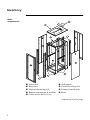
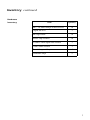
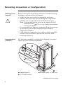
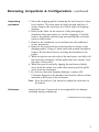
NetShelter®
Standard
Enclosure
AR500
User’s Manual
®
This manual is available in English on the enclosed NetShelter CD.
Dieses Handbuch ist in Deutsch auf der beiliegenden NetShelter CD-ROM
verfügbar.
Este manual está disponible en español en el CD-ROM de NetShelter adjunto.
Ce manuel est disponible en français sur le CD-ROM NetShelter ci-inclus.
Questo manuale è disponibile in italiano nel CD-ROM NetShelter allegato.
O manual em Português está disponível no CD-ROM NetShelter em anexo.
Contents
Introduction and Setup . . . . . . . . . . . . . . . . . . . . .1
Product Overview . . . . . . . . . . . . . . . . . . . . . . . . . . . . . . . . 1
Features of the enclosure 1
Inventory . . . . . . . . . . . . . . . . . . . . . . . . . . . . . . . . . . . . . . 2
Main components 2
Hardware inventory 3
Receiving, Inspection & Configuration . . . . . . . . . . . . . . . . 4
Warnings and cautions
4
Unpacking the enclosure 4
Unpacking procedure 5
Disclaimer 5
Taking inventory 6
Configuration 6
Blanking panels
6
Stabilizing the Enclosure . . . . . . . . . . . . . . . . . . . . . . . . . . . 7
Leveling feet 7
Leveling procedure 7
Stabilizer Plate Kit 7
Customizing the Enclosure . . . . . . . . . . . . . . . . . . .8
Preliminary Information . . . . . . . . . . . . . . . . . . . . . . . . . . . 8
Removing the side panels 8
Reversing the Door . . . . . . . . . . . . . . . . . . . . . . . . . . . . . . . 9
Installing Equipment . . . . . . . . . . . . . . . . . . . . . . . . . . . . 10
Identifying one U-space 10
Caged nuts 11
Installing caged nuts 11
Removing caged nuts 11
i
Contents continued
Cable Management . . . . . . . . . . . . . . . . . . . . . . . . . . . . . 12
Removing the roof 12
Three floor openings for cable access 13
Using a knockout panel 13
Vertical Mounting Rails . . . . . . . . . . . . . . . . . . . . . . . . . . . 14
Adjusting the rails 14
Moving the rails 15
Joining Enclosures . . . . . . . . . . . . . . . . . . . . . . . . . . . . . . 16
Product Specifications . . . . . . . . . . . . . . . . . . . . .17
Warranty Information . . . . . . . . . . . . . . . . . . . . . . . . . . . . 17
Limited warranty 17
Obtaining service 17
Warranty limitations 17
Specifications . . . . . . . . . . . . . . . . . . . . . . . . . . . . . . . . . . 18
ii
Introduction and Setup
Product Overview
This American Power Conversion (APC) NetShelter® Standard
Enclosure (AR500) provides storage for industry-standard
(EIA-310-D) 19" rack-mount hardware, including servers,
voice, data, networking, internetworking, and APC power
protection equipment.
Features of the
enclosure
•
•
•
•
•
•
•
•
•
•
40U (70") storage height for 19" rack-mount equipment
Fully ventilated doors and roof
Smoked, tempered glass front door
Front and rear door locks
Quick-release side panels with locks
Cable access on the roof, bottom, and rear
Adjustable leveling feet
Heavy-duty casters
Adjustable vertical mounting rails
Ample clearance for wiring between front door and
mounting rails
• Quick-release reversible front and rear doors
• Rolls through a two-meter door
1
Inventory
Main
components
Front door
Rear door
Vertical mounting rails
Braces (top/bottom & middle)
Cable access hole covers
Side panels
Casters/leveling feet
Frame (front & rear)
Roof
Continued on next page
2
Inventory continued
Hardware
inventory
Item
Quantity
M6 × 16 mm Phillips/slotted screws
30
Caged nut tool
1
M6 caged nuts
30
Plastic cup washers
30
13 mm/14 mm open-end wrench
1
5 mm Allen wrench
1
Door/side panel keys
4
Grommet strips
2
3
Receiving, Inspection & Configuration
Warnings and
cautions
Before you begin to unpack the enclosure, read the following
warnings to prevent injury and damage:
• It takes at least two persons to unpack the enclosure.
• Stabilize the enclosure before installing the components.
Failure to do so could allow the enclosure to tip over.
Note: You can stabilize the enclosure by adding the APC
Stabilizer Plate (AR8115), or by joining two or more
enclosures together.
• Do not extend more than one component from the enclosure
at one time to prevent the enclosure from becoming
dangerously unstable.
• Load heaviest components first and place them toward the
bottom of the enclosure to prevent the enclosure from
becoming top-heavy.
Unpacking the
enclosure
The enclosure assembly is packaged for shipping. You must
unpack it before installing equipment.
Shipping pallet
13/14 mm wrench
Brackets with 13 mm bolts
Continued on next page
4
Receiving, Inspection & Configuration continued
Unpacking
procedure
1. Move the shipping pallet containing the enclosure to a firm,
level surface. The area must be large enough and free of
clutter. Inspect the enclosure for visible signs of shipping
damage.
2. Refer to the label on the exterior of the packaging to
determine the proper place to cut the wrapping. Carefully
remove the plastic stretch-wrap surrounding the enclosure
using a utility knife.
3. Remove the cardboard cover and the four tall cardboard
corner protectors.
4. Remove the four brackets anchoring the enclosure to the
shipping pallet. Using a 13mm open-end wrench (included),
remove the hex head screws securing the brackets to the
pallet.
5. With one person on each side of the enclosure, carefully roll
the enclosure assembly off the pallet until two casters clear
the edge of the pallet.
6. With one person carefully tipping the enclosure slightly
away from the pallet, have the other person pull the pallet
away from the enclosure.
7. If you have detected shipping damage, contact APC
Customer Support at the number listed on the yellow sticker
attached to the front of the enclosure.
Note: Save the pallet if you intend to reship the enclosure in
the future.
Disclaimer
American Power Conversion is not responsible for damage
sustained during reshipment.
Continued on next page
5
Receiving, Inspection & Configuration continued
Taking
inventory
After unpacking the enclosure, verify that all required
components and hardware have been shipped with the
enclosure. (See “Inventory” starting on page 2.)
Note: If any items are missing, contact APC Customer Support
using a phone number or URL listed on the back cover
of this manual.
Configuration
Before installing your enclosure, you should give some
thought to the location of components within the enclosure.
You must consider the proximity needed by some components,
ergonmics of keyboards and video monitors, and the available
space.
The NetShelter Configurator, available on the APC Web site,
helps you plan your configuration to maximize the available
space of your enclosure.
Blanking panels
6
To maintain proper air flow, cover any empty vertical
enclosure space with blanking panels (AR8101, not
included). Improper air flow could damage installed
components.
Stabilizing the Enclosure
Warning
To avoid tipping damage or personal injury, move the
enclosure to its permanent location and level it before you
load equipment.
Leveling feet
Leveling feet are attached under the enclosure at each corner.
They provide a stable base if the selected floor space is uneven
but are not intended to compensate for a badly sloped surface.
Leveling
procedure
1. Move the enclosure to a relatively level location.
2. Fit the 14 mm open-end wrench (included) to the hex nut
just above the round pad on the bottom of a leveling foot.
Turn the wrench clockwise to extend the leveling foot until
it makes firm contact with the floor surface.
3. Repeat step 2 for each of the remaining leveling feet.
4. Use a spirit level to determine which feet need further
adjustment to level the enclosure. Adjust as necessary.
Stabilizer Plate
Kit
APC offers a Stabilizer Plate (AR8115) for attaching to the
enclosure frame with 8 mm socket head cap screws. The plate
may also be bolted to the floor to add stability.
7
Customizing the Enclosure
Preliminary Information
The enclosure is complete upon arrival and needs no further
assembly. This chapter provides instructions on how to adjust
the enclosure to accommodate particular components or site
configurations.
Removing the
side panels
Customizing requires access to the interior of the enclosure by
removing the side panels or opening the front or rear door. To
remove a side panel:
1. Use the key to unlock the panel (at top).
2. Tip the top of the panel outward about 30°, as shown.
3. Lift the panel up and off the two vertical slots at the
bottom of the enclosure.
8
Reversing the Door
The front and rear doors may be removed or reversed to
accommodate various site configurations. To reverse a door:
1. Remove the door.
a. Pull down on the quick-release pin ➼ of the upper
hinge.
b. Swing the top away from the hinge and lift the door
straight up and off the bottom hinge. Set aside.
2. Remove the hinge bushings ➽✝and reinstall on the other
side ➾. To remove a bushing, insert the end of a slotted
screwdriver into the round opening and pry outward.
3. Flip the door and reinstall on the other side.
Note: You can change the direction of the handle by rotating the cam on the lock.
9
Installing Equipment
For specific information on how to mount rack-equipment in
the enclosure, see the installation instructions provided with
the equipment.
Identifying one
U-space
When installing equipment, you will usually be required to
locate the beginning and end of a U-space on the vertical
mounting rails. Every third mounting hole on the vertical
mounting rails of a NetShelter enclosure is notched to indicate
the middle of a U-space. A U-space takes up one of these
notched holes and one hole immeadiately above and below it,
as shown in the figure below.
Continued on next page
10
Installing Equipment continued
Caged nuts
During installation of equipment in you enclosure, you may
need to install or remove caged nuts.
Warning
Install caged nuts horizontally; that is, the ears of the caged
nut should engage the sides of the mounting hole. Do NOT
install caged nuts with the ears engaging the top and
bottom of the mounting hole.
Installing caged
nuts
1. Install caged nuts on the back of the mounting rails, opposite the equipment to be mounted.
2. Insert the caged nut into the mounting hole by hooking one
ear of the caged nut through the far side of the hole.
3. Place the caged nut tool (included) on the other ear of the
caged nut and pull forward to snap it into position.
Removing caged
nuts
1. Remove any attached screw.
2. From the outside of the rail, hook the caged nut tool along
an ear of the caged nut and press inward to pinch the ear.
3. When the ear is clear of the mounting hole, push the caged
nut gently through the hole. Grasp the caged nut before
releasing the tool.
11
Cable Management
Removing the
roof
You can remove the roof of the enclosure to install a NetShelter
Fan Tray (AR8210, AR8211) or to improve cable access.
Continued on next page
12
Cable Management continued
Three floor
openings for
cable access
The floor of the enclosure has three openings for cable access:
one large opening in the middle of the floor ➼, and two knockout panels ➽.
Using a
knockout panel
1. Remove the knockout panel using a hammer.
2. Install a rubber grommet (included) onto the edge of the
opening to protect cabling.
13
Vertical Mounting Rails
The vertical mounting rails are preset for use with Compaq®
rack-mountable equipment, at a depth of 29.13" (739 mm).
Front and rear vertical mounting rails can be adjusted a total of
3.23" (82 mm) to accommodate different rails or components
with various depths. You can also move the front and rear
vertical mounting rails forward or backward within the
enclosure by attaching them to the horizontal braces.
Adjusting the
rails
1. Use the 5 mm Allen wrench (included) to loosen (but not
remove) the socket-head screws ➼ in the slots ➽ of the vertical mounting rail.
2. Slide the vertical mounting rail forward or rearward to the
desired position. Tighten.
Continued on next page
14
Vertical Mounting Rails continued
Moving the rails
1. Refer to “Adjusting the rails” on page 14. Use the 5 mm
Allen wrench (included) to remove the socket-head screws
➼ in the slots ➽ of the vertical mounting rail.
2. Move the rail to its new position and secure it to each
horizontal brace ➾:
a. Insert a caged nut into the appropriate holes at the
new position on each horizontal brace.
b. Place the vertical mounting rail at the new position
and insert a socket-head screw through the rail and
tighten.
15
Joining Enclosures
To join two or more enclosures together to form a larger,
multi-bay enclosure:
1. Place the enclosures together, with their frames touching
each other.
2. Connect the enclosures at the top and bottom of each
frame✝➼ using an M6 × 16 mm Phillips/slotted screw
(included) .
16
Product Specifications
Warranty Information
Limited
warranty
APC warrants the NetShelter Standard Enclosure to be free
Obtaining
service
To obtain service under warranty you must obtain a returned
material authorization (RMA) number from APC or a
designated APC service center. (Before contacting APC, open
the rear door of the enclosure and locate the serial number on
the center of the top enclosure frame.) Products must be
returned to APC or an APC service center with transportation
charges prepaid and must be accompanied by a brief
description of the problem encountered and proof of date and
place of purchase.
Warranty
limitations
Except as provided herein, American Power Conversion
makes no warranties, express or implied, including
warranties of merchantability and fitness for a particular
purpose. Some jurisdictions do not permit limitation or
exclusion of implied warranties; therefore, the aforesaid
limitation(s) or exclusion(s) may not apply to the purchaser.
from defects in materials and workmanship for a period of two
years from the date of purchase. Its obligation under this
warranty is limited to repairing or replacing, at its own sole
option, any such defective products. This warranty does not
apply to equipment which has been damaged by accident,
negligence, or misapplication or has been altered or modified
in any way. This warranty applies only to the original
purchaser.
Except as provided above, in no event will APC be liable
for direct, indirect, special, incidental, or consequential
damages arising out of the use of this product, even if
advised of the possibility of such damage.
Specifically, APC is not liable for any costs, such as lost profits
or revenue, loss of equipment, loss of use of equipment, loss of
software, loss of data, costs of substitutes, claims by third
parties, or otherwise. This warranty gives you specific legal
rights and you may also have other rights which vary from
state to state.
17
Specifications
Item
18
Measurement
Height
76.4 in. (194 cm)
Width
24.0 in. (60.7 cm)
Depth
34.4 in. (87.4 cm)
Clearance (for wiring between
front door and vertical rail)
2.2 in. (5.6 cm)
Net Weight
274 lb (125 kg)
Ventilation (front door)
132 sq. in. (852 cm2)
Ventilation (rear door)
593 sq. in. (3826 cm2)
Ventilation (roof)
177 sq. in. (1142 cm2)
APC Worldwide Customer Support
Customer support for this or any other APC product is available at no charge in any of
the following ways:
•
Visit the APC Web site to find answers to frequently asked questions
(FAQs), to access documents in the APC Knowledge Base, and to submit
customer support requests.
– http://www.apcc.com (Corporate Headquarters)
Connect by links to APC Web pages for specific countries and regions,
each of which provides customer support information.
– http://www.apcc.com/support/
Submit customer support requests.
•
Contact an APC Customer Support center by telephone or e-mail.
– Regional centers:
.
–
•
APC Headquarters
(U.S. and Canada)
(1) (800) 800-4272 (toll free)
Latin America
(1) (401) 789-5735 (United States)
[email protected]
Europe, Middle East,
Africa
(353) (91) 702020 (Ireland)
[email protected]
Japan
(03) 5434-2021
[email protected]
Local, country-specific centers: go to http://www.apcc.com/support/
contact for contact information.
Contact the APC representative or other distributor from whom you purchased your APC product for information on how to obtain local customer
support.
Entire contents copyright © 2001 American Power Conversion. All rights reserved. Reproduction
in whole or in part without permission is prohibited. APC and NetShelter are registered
trademarks of American Power Conversion Corporation. All other trademarks,
product names, and corporate names are the property of their respective
owners and are used for informational purposes only.
990-6031A
02/2001