1
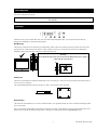
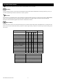
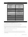
APC PowerStack 450
100V
Uninterruptible Power Supply
User’s Manual
Notice: In case of a problem with this product, do not return to the place of purchase. Go to the support
page at www.apcc.com for Technical Support or call 1-800-800-4272 for prompt customer service.
990-5022A, Revision 2 6/99
PowerStack 450 Quick Reference Guide
English
About Your New PowerStack UPS
Troubleshooting
This Uninterruptible Power Supply (UPS) is designed to prevent
blackouts, brownouts, sags and surges from reaching your computer
and other valuable electronic equipment. This UPS also filters out
small utility line fluctuations and isolates your equipment from large
disturbances by internally disconnecting from the utility line, while
supplying power from its internal batteries until the utility line
returns to safe levels.
Use the chart below to solve minor UPS installation problems.
Contact APC for assistance with complex UPS problems. See the
User’s Manual for a location near you.
While running on battery, an internal alarm will sound (periodic
beeps).
If the utility power does not return, the UPS will continue supplying
power to the connected equipment until exhausted. A continuous
beeping will sound two minutes before the UPS’s final low battery
shutdown. If using a computer, you must manually save your files
and power down before the UPS turns itself off.
Installation and Setup
1. Install UPS
•
Plug the power cord into the power supply.
Problem and
Possible Cause
UPS will not turn on.
Solution
• ON button not pushed.
Press the ON button once to power the
UPS and the load.
Check that the power cable from the
UPS to the power supply is securely
connected to the AC power source.
Reduce the load on the UPS by
unplugging equipment and reset the
circuit breaker (on back of UPS) by
pressing the plunger back in.
Check the AC power supply to the UPS
with a table lamp. If very dim, have
the utility voltage checked.
Confirm the battery connections.
• UPS not connected to AC
power supply.
• UPS input circuit breaker
tripped.
• Very low or no utility
voltage.
• Battery not connected
properly.
UPS will not turn off.
• Internal UPS fault.
Do not attempt to use the UPS. Unplug
the UPS and have it serviced
immediately.
UPS operates on-battery although normal line voltage exists.
2. Connect Equipment
•
Do not power laser printers through the UPS.
•
Use your equipment’s power cords to connect to
the UPS.
•
Turn on all connected equipment.
3. Turn on UPS
I
•
Press the UPS’s ON switch to turn on your UPS.
This will power-up connected equipment.
•
The unit performs a self-test automatically when
turned on, and every two weeks thereafter.
•
The UPS charges its battery whenever it is
connected to utility power. The battery charges
fully during the first 4 hours of normal operation.
Do not expect full runtime during this initial charge
period.
• UPS’s input circuit breaker
tripped.
• Very high, low, or distorted
line voltage..
Reduce the load on the UPS by
unplugging equipment and reset the
circuit breaker(on back of UPS) by
pressing the plunger back in.
Move the UPS to a different outlet on a
different circuit.
UPS beeps occasionally.
• Normal UPS on battery
operation.
None. The UPS is protecting the load.
UPS does not provide expected backup time.
• The UPS’s battery is weak
due to recent outage or is
near the end of its service
life.
• The UPS is overloaded.
Charge the battery. Batteries require
recharging after extended outages.
Also, they wear faster when put into
service often or when operated at
elevated temperatures. If the battery is
near the end of its service life, consider
replacing the battery even if the replace
battery indicator is not yet lit.
Check the UPS’s load display. Unplug
less needed equipment, such as printers.
All indicators are lit and UPS emits a constant beeping.
• Internal UPS fault.
Do not attempt to use the UPS. Turn
the UPS off and have it serviced
immediately.
Overload indicator is on and beeps constantly.
• UPS is overloaded.
Unplug less needed equipment, such as
printers.
The replace battery light is lit.
• Weak batteries.
• Replacement batteries not
connected properly.
990-5022A, Revision 2 6/99
Do another self test to see if it clears.
Confirm the battery connections.
Table of Contents
Safety........................................................................................................................................................................................................... 1
Initial Inspection........................................................................................................................................................................................ 3
Installation.................................................................................................................................................................................................. 3
Setup............................................................................................................................................................................................................ 5
Operating Instructions ............................................................................................................................................................................ 5
LEDs and Audible Alarms ....................................................................................................................................................................... 6
Operating Modes ...................................................................................................................................................................................... 7
Storage........................................................................................................................................................................................................ 7
Replacing the Battery Pack.................................................................................................................................................................... 8
Specifications............................................................................................................................................................................................ 9
Service ........................................................................................................................................................................................................ 9
APC Japan Contact Information..........................................................................................................................................................10
Limited Warranty....................................................................................................................................................................................10
990-5022A, Revision 2 6/99
Safety
This section contains important instructions that should be followed during installation and maintenance of the PowerStack 450 and
batteries. It is intended for customers who setup, install, relocate, or maintain APC equipment.
Electrical Safety
•
Do not work alone under hazardous conditions.
•
High short circuit current through conductive materials could cause severe burns.
•
Check that the power cord(s), plug(s), and sockets are in good condition.
•
To reduce the risk of electric shock when grounding cannot be verified, disconnect the equipment from the AC power outlet before
installing or connecting to other equipment. Reconnect the power cord only after all connections are made.
•
Do not handle any kind of metallic connector before the power has been removed.
•
Use one hand, whenever possible, to connect or disconnect signal cables to avoid a possible shock from touching two surfaces with
different electrical grounds.
•
Connect the equipment to a three wire AC outlet (two poles plus ground). The receptacle must be connected to appropriate branch
circuit/mains protection (fuse or circuit breaker). Connection to any other type of receptacle may result in a shock hazard.
CAUTION! Deenergizing Safety
•
If the equipment has an internal energy source (the battery), the output may be energized when the unit is not connected to an AC
power outlet.
•
To deenergize: first press the Off button for more than one second to switch the equipment off. Next disconnect the equipment
from the AC power outlet. Finally, disconnect the battery.
•
Pluggable equipment includes a protective earth conductor which carries the leakage current from the load devices (computer
equipment). Total leakage current must not exceed 3.5 mA .
•
Use of this equipment in life support applications where failure of this equipment can reasonably be expected to cause the failure
of the life support equipment or to significantly effect its safety or effectiveness is not recommended.
WARNING! Battery Safety
•
This equipment contains potentially hazardous voltages. Do not attempt to disassemble the unit. The only exception is for
equipment containing batteries. Battery replacement using the procedures below is permissible. Except for the battery, the unit
contains no user serviceable parts. Repairs are performed only by factory trained service personnel.
Batteries must be recycled. Deliver the battery to an appropriate recycling facility or ship it to the supplier in
the new battery’s packing material. See the new battery instructions for more information.
•
Do not dispose of batteries in a fire. The batteries may explode.
•
Do not open or mutilate batteries. They contain an electrolyte which is toxic and harmful to the skin and eyes.
•
To avoid personal injury due to energy hazard, remove wrist watches and jewelry such as rings when replacing the batteries. Use
tools with insulated handles.
•
Replace batteries with the same number and type of batteries as originally installed in the equipment.
Handling Safety
⇒
⇒
<18 kg (<40 lb.)
⇒
32-55 kg (70-120 lb.)
18-32 kg (40-70 lb.)
•
⇒ >55 kg (>120 lb.)
Be careful. Do not lift heavy loads without assistance.
•
Equipment with casters is built to move on a smooth surface without any obstacles.
1
990-5022A, Revision 2 6/99
•
Do not use a ramp inclined at more than 10°.
•
This equipment is intended for installation in a temperature-controlled (0° - 40° C) indoor area, free of conductive contaminants.
990-5022A, Revision 2 6/99
2
Initial Inspection
Inspect the APC PowerStack 450 UPS upon receipt. Notify the carrier and dealer if there is damage. The packaging is recyclable; save
it for reuse or dispose of it properly.
Warning: Changes or modifications to this unit not expressly approved by the party responsible for compliance could void
the warranty.
Installation
Placement
Install the UPS in a protected area that is free of excessive dust and has adequate air flow. Do not operate the UPS where the
temperature and humidity is outside the specified limits.
Wall Mounting
The brackets on the UPS can be rotated 90° for wall mounting. Remove the screws, rotate the brackets, and insert the screws in the
appropriate holes. Wall-mount the unit with the controls towards or at the top, not at the bottom of the unit. The illustrations
immediately below show the proper positions for wall mounting the unit.
Warning!
Do not mount the unit on the wall as shown in the illustrations below. Doing so
could result in a safety hazard.
Desktop Use
This UPS is provided with four adhesive-backed rubber “feet” for desktop use. Attach the feet to the bottom of the unit and remove
the ears to use it on a desktop.
The recommended placement of the feet is shown by a small + on the bottom corners of the unit:
Front of Unit
Bottom of Unit
Rack Mounting
The UPS comes with standard 19” (46.5 cm) rack mount brackets. It is supplied with four (4) screws to attach the mounting brackets
(ears) to the chassis.
Select a rack location with adequate air flow that is free from excessive dust. Ensure that the air vents on the sides of the UPS are not
blocked. Do not operate the UPS where temperature or humidity are outside the limits listed in Specifications, page 9.
3
990-5022A, Revision 2 6/99
990-5022A, Revision 2 6/99
4
Setup
Note: The UPS will not power up initially unless the AC voltage is in the normal operating range.
Rear View
Plug the power cord into the power supply.
Connect equipment to the output receptacles.
•
Do not power laser printers through the UPS.
•
Use your equipment’s power cords to connect to the UPS.
•
Turn on all connected equipment.
Battery Pack Charge
The UPS charges its battery pack whenever it is connected to utility power. The battery pack will charge fully during the first four
hours of normal operation. Do not expect full battery back-up runtime during this initial charge period.
Computer Interface Port
The optional PowerChute® plus software from APC allows communication with the UPS through this port. PowerChute® plus can be
used to monitor and customize the UPS performance for a variety of operating conditions. Contact APC for software availability.
Operating Instructions
With the UPS plugged in, press and release the on/off/test button to supply power to the loads. The loads are immediately
powered while the UPS beeps and performs a self-test.
Press and release the on/off/test button to turn off power to the loads. It may be convenient to use the UPS as a master on/off
switch for the protected equipment.
Note: Whenever the UPS is plugged in and utility voltage is present, the charger maintains battery charge .
5
990-5022A, Revision 2 6/99
LEDs and Audible Alarms
The on-line LED illuminates when the UPS is supplying utility power to the loads.
On Battery
During on-battery operation, the on-battery LED illuminates and the UPS sounds an audible alarm consisting of four beeps every 30
seconds. The alarm stops when the UPS returns to on-line operation.
Overload
When the UPS is overloaded (when the connected loads exceed the maximum specified in the “maximum load” listed in Specifications,
page 9.), the overload LED comes on and the UPS emits a sustained tone. The alarm remains on until the overload is removed.
Disconnect nonessential load equipment from the UPS to eliminate the overload.
Replace Battery
If the battery fails a self-test, the UPS emits short beeps for one minute and the replace battery LED illuminates. The UPS repeats the
alarm every five hours. Perform the self-test procedure to confirm replace battery conditions. The alarm stops when the battery passes
the self-test.
Function
UPS is on
UPS is running on battery
UPS is performing self-test
Overload
Overload shutdown
Output short circuit
Transformer failure
Low Battery (while on battery)
Replace battery condition
Battery disconnected in self test
UPS internal alarms:
boost/trim failure
transfer relay weld
sleep mode
LED
— = irrelevant to condition
m = on steady
X = flashing
l = Off
990-5022A, Revision 2 6/99
LED
l
m
m
m
l
X
—
—
—
—
m
—
—
—
—
—
—
l
—
l
X
X
—
Key:
X
X
X
Tone
l
l
—
l
m
m
m
m
—
l
—
—
l
l
X
X
—
—
—
—
—
m
l
l
X
—
—
4
—
1
1
1
1
1
2
3
1
1
—
Tone
— = irrelevant to condition
1 = sustained tone
2 = 1 minute of beeping every 5 hours
3 = fading tone
4 = 4 beeps every 30 seconds
6
Operating Modes
Shutdown Mode
In shutdown mode the UPS stops supplying power to the load, waiting for the return of utility power. If there is no utility power
present, external devices (e.g., servers) connected to the computer interface can command the UPS to shut down. This is normally done
to preserve battery capacity after the graceful shutdown of protected servers. The on-line and overload LEDs will blink alternately
when the UPS is in shutdown mode.
Self-test
The UPS performs a self-test automatically when turned on, and every two weeks thereafter (by default). Automatic self-test eases
maintenance requirements by eliminating the need for periodic manual self-tests.
During the self-test, the UPS briefly operates the loads on-battery. If the UPS passes the self-test, it returns to on-line operation.
If the UPS fails the self-test it immediately returns to on-line operation and lights the replace battery LED.
The loads are not affected by a failed test. Recharge the battery overnight and perform the self-test again. If the replace battery LED is
still on, replace the battery using the procedure described in Replacing the Battery Pack, page 8.
Low Battery
When the UPS is operating on-battery and the energy reserve of the battery runs low, the UPS beeps continuously until the UPS shuts
down from battery exhaustion or returns to on-line operation.
Cold Start
When the UPS is off and there is no utility power, use the cold start feature to apply power to the loads from the UPS’s battery.
Note: Cold start is not a normal condition.
•
Press and hold the on/off/test button until the UPS emits a constant tone.
• Release the on/off/test button during the tone to start the UPS.
Storage
Storage Conditions
Store the UPS covered and upright in a cool, dry location, with its battery fully charged. Before storing, charge the UPS for at least four
hours.
Extended Storage
At -15 to +30 °C (+5 to +86 °F), charge the UPS’s battery every 6 months.
At +30 to +45 °C (+86 to +113 °F), charge the UPS’s battery every 3 months.
7
990-5022A, Revision 2 6/99
Replacing the Battery Pack
This UPS has an easy to replace hot-swappable battery pack.
Note: Please read the cautions in the APC Safety Guide.
Replacement Batteries
See your dealer or call the number in this manual for information on replacement battery pack kits, order RBC18.
Battery Pack Replacement Procedure
Battery pack replacement is a safe procedure, isolated from electrical hazards. You may leave the UPS and loads on for the following
procedure.
Notes
•
Once the battery pack is disconnected, the loads are not protected from power outages.
•
Be careful removing the batteries - they are heavy.
•
Small sparks at the battery connectors are normal during connection.
APC
1.
Reach into the finger pull and remove the front cover.
2.
Use a flat-blade screwdriver to turn the two battery door screws ¼ turn counterclockwise; open the
door.
3.
Grasp the clear plastic tab and gently pull the battery pack out of the UPS until the battery connector
is visible.
Warning! Do not force the battery pack out. This may damage internal wiring!
4.
Disconnect the battery connector by gripping both sides of the connector and firmly pulling them
apart.
5.
Slide the battery pack out of the UPS.
6.
Slide the new battery pack three-fourths of the way into the UPS.
7.
Connect the battery connector attached to the unit to the connector attached to the new battery pack.
8.
Push the battery pack in as far as it will go. There are stops in the back to prevent it from going too
far.
9.
Close the battery door, turn the battery compartment screws ¼ turn clockwise, and replace the front
cover.
Batteries must be recycled. Deliver the battery to an appropriate recycling facility or ship it to the
supplier in the new battery’s packing material. See the new battery instructions for more information.
990-5022A, Revision 2 6/99
8
Specifications
Acceptable input voltage
Input voltage (on-line operation)
Nominal Range
Maximum Range
Output voltage)
Nominal Range
Maximum Range
Input Over Current Protection
Frequency limits (on-line operation)
Transfer time
Maximum load
On-battery output voltage
On-battery frequency
On-battery waveshape
Output Over Current Protection
0 - 150 VAC
User adjustable through PowerChute® plus.
74-119 VAC
69-126 VAC
User adjustable through PowerChute® plus.
92-108 VAC
86-114 VAC
Resettable circuit breaker
47 - 63 Hz
5.5 ms typical, blackout response time
450 VA 280 W
100 VAC
50 or 60 Hz, ±0.1 Hz; synchronized to utility
Stepped sine-wave
Overcurrent and short-circuit protected,
latching shutdown on overload
Spill proof, maintenance free, sealed leadacid
3 to 6 years, depending on number of
discharge cycles and ambient temperature
4 to 8 hours from total discharge
0 to +40 °C (+32 to +104 °F)
-15 to +45 °C (+5 to +113 °F)
5 to 95%, non-condensing
0 to +3,000 m (0 to +10,000 ft)
0 to +15,000 m (0 to +50,000 ft)
<38 dBA
1.75 x 17.5 x 13.0 in.
22.5 (26.5) lb.
UL1449, UL1778
VCCI Class A
Battery type
Typical battery life
Typical recharge time
Operating temperature
Storage temperature
Operating and storage relative humidity
Operating elevation
Storage elevation
Audible noise at 1 m (3 ft)
Size (H x W x D)
Weight - net (shipping)
Safety and approvals
EMC Emissions
Service
If the UPS requires service do not return it to the dealer! Follow these steps:
1. Use the Troubleshooting section of the Quick Reference Guide to eliminate common problems.
2. Verify that no circuit breakers are tripped. A tripped circuit breaker is the most common UPS problem!
3. If the problem persists, call customer service or visit the APC Internet Website (www.apcc.com).
4. Note the model number of the UPS, the serial number, and the date purchased. A technician will ask you to describe the problem and
try to solve it over the phone, if possible. If this is not possible the technician will issue a Return Merchandise Authorization Number
(RMA#).
5. If the UPS is under warranty, repairs are free. If not, there is a repair charge.
6. Disconnect the batteries before packing the UPS.
7. Pack the UPS in its original packaging. If the original packing is not available, ask customer service about obtaining a new set.
8. Pack the UPS properly to avoid damage in transit. Never use Styrofoam beads for packaging. Damage sustained in transit is not
covered under warranty.
9
990-5022A, Revision 2 6/99
9. Include a letter with your name, RMA#, address, copy of the sales receipt, description of the trouble, your daytime phone number,
and a check (if necessary).
10.Mark the RMA# on the outside of the package.
11.Return the UPS by insured, prepaid carrier to the address given to you by Customer Service.
APC Japan Contact Information
Japan……….…………….03-5434-2021
Internet and
Customer
Support
http://www.apc.co.jp
E-mail: [email protected]
Address:
APC Japan, Inc.
BR Gotanda Bldg. 7F
2-30-4 Nishi- gotanda, Shinagawa-ku
Tokyo 141-0031
Limited Warranty
American Power Conversion (APC) warrants its products to be free from defects in materials and workmanship for a period of two years
from the date of purchase. Its obligation under this warranty is limited to repairing or replacing, at its own sole option, any such defective
products. To obtain service under warranty you must obtain a Returned Material Authorization (RMA) number from customer support (see
the Service section of the User’s Manual). Products must be returned with transportation charges prepaid and must be accompanied by a brief
description of the problem encountered and proof of date and place of purchase. This warranty does not apply to equipment which has been
damaged by accident, negligence, or misapplication or has been altered or modified in any way. This warranty applies only to the original
purchaser who must have properly registered the product within 10 days of purchase.
EXCEPT AS PROVIDED HEREIN, AMERICAN POWER CONVERSION MAKES NO WARRANTIES, EXPRESSED OR IMPLIED,
INCLUDING WARRANTIES OF MERCHANTABILITY AND FITNESS FOR A PARTICULAR PURPOSE. Some states do not permit
limitation or exclusion of implied warranties; therefore, the aforesaid limitation(s) or exclusion(s) may not apply to the purchaser.
EXCEPT AS PROVIDED ABOVE, IN NO EVENT WILL APC BE LIABLE FOR DIRECT, INDIRECT, SPECIAL, INCIDENTAL, OR
CONSEQUENTIAL DAMAGES ARISING OUT OF THE USE OF THIS PRODUCT, EVEN IF ADVISED OF THE POSSIBILITY OF SUCH
DAMAGE. Specifically, APC is not liable for any costs, such as lost profits or revenue, loss of equipment, loss of use of equipment, loss of
software, loss of data, costs of substitutes, claims by third parties, or otherwise.
990-5022A, Revision 2 6/99
10