1
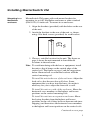
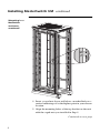
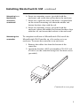
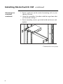
™
MasterSwitch VM
Power Distribution Unit
AP9221X166
AP9221EXPX166
Installation and
Quick Start Manual
®
Thank You!
Thank you for selecting the APC MasterSwitch VM
(vertical-mount) power distribution unit (PDU). It has been
designed for many years of reliable, maintenance-free
service. APC is dedicated to the development of highperformance electrical power conversion and control
products. We hope that you will find this product a valuable,
convenient addition to your system.
Please read this manual! It provides important safety,
installation, and operating instructions that will help you get
the most from your MasterSwitch VM unit.
Additional Documentation
This Installation and Quick Start Manual and the online
User Guide are available on the supplied CD or on our Web
site: http://www.apcc.com/. The online User Guide contains
additional information about the following topics related to
MasterSwitch VM:
• detailed product description
• current sensing capabilities
• management interfaces
• user accounts
• customizing setup
• outlet control actions
• security
• obtaining customer service
• product information (LEDs, warranty, life-support
policy, specifications)
Contents
Preliminary Information . . . . . . . . . . . . . . . . . . . . . 1
Features of MasterSwitch VM 1
Inventory 2
Please recycle 2
Installing MasterSwitch VM . . . . . . . . . . . . . . . . . . 3
Mounting in a NetShelter enclosure 3
Mounting the controller 5
Hardwiring procedure 7
Connecting MasterSwitch VM . . . . . . . . . . . . . . . . . 8
Caution 8
Setting up a single unit 8
Setting up multiple units 9
Quick Configuration . . . . . . . . . . . . . . . . . . . . . . 10
Required configuration 10
Configuring TCP/IP settings 10
Accessing MasterSwitch VM 14
i
Preliminary Information
Features of
MasterSwitch
VM
American Power Conversion’s MasterSwitch VM is a
vertically-mounted, stand-alone, network-manageable power
distribution unit (PDU) designed to accommodate a total of 16
outlets: eight individually-managed outlets and eight alwayson outlets. You can control MasterSwitch VM through
available Web, Control Console, or SNMP interfaces.
Additional features of MasterSwitch VM include:
• Independent control of each outlet for:
– Power On Delay
– Power Off Delay
– Reboot Duration
• Three levels of user access accounts:
– Administrator
– Device Manager
– Outlet User (16 independent accounts)
• An audible overload alarm to measure current for:
– overload
– user-set overload
– user-set low load
• Basic and MD5 authentication password security.
• A sleek, vertical design that occupies no U-space in a
rack environment. Includes rack-mount brackets for
mounting in an APC NetShelter® or other standard
(EIA310-D) 19-inch rack.
• Synchronized switching across units to permit control of
redundant-feed devices.
• The capability of being daisy-chained in a series of up to
four units, thereby providing outlet management control
for up to 32 outlets (with an additional 32 always-on
outlets).
• A versatile design that allows units to be easily hardwired.
• Event Logging of the MasterSwitch VM unit’s last 300
events.
• Auto-configuration feature, allowing customized
configuration of all units from one ASCII text file.
Continued on next page
1
Preliminary Information continued
Inventory
MasterSwitch VM (AP9221X166) comes with the following
items:
Item
Please recycle
2
Part Number
Quantity
MasterSwitch VM unit
AP9221EXPX166
1
MasterSwitch VM Controller
with a pre-installed Web/
SNMP SmartSlot Card
AP9221NX166
Communication cable
607-0035A
1
Configuration cable
940-0024
1
CD-ROM containing product
documentation and the
Management Card Wizard
991-1055C
Brackets for the unit with 14
flat-head screws
870-8215
Brackets for the controller
with 4 flat-head screws
870-8213 and 8708183
Installation and Quick Start
Manual
990-6020A
Warranty registration card
N/A
1
1
3
2
1
1
The shipping materials for MasterSwitch VM are recyclable.
Please save them for later reuse or dispose of them
appropriately.
Installing MasterSwitch VM
Mounting in a
NetShelter
enclosure
MasterSwitch VM comes with rack-mount brackets for
mounting in an APC NetShelter enclosure or other standard
(EIA310-D ) 19-inch rack. To mount in an enclosure:
1. Align the brackets (provided) with the holes on the rear
of the unit.
2. Attach the brackets to the rear of the unit, as shown,
using 4 flat-head screws (provided) for each bracket.
3. Choose a suitable location for the unit. The figure on
page 4 shows the unit mounted in four different
locations in the enclosure.
Note: To avoid interfering with shelves or equipment, install
the unit so that it hangs on the outside edge of the
vertical rail. The figure on page 4 and the suggestions
below illustrate how to orient the brackets with the
vertical mounting rail.
To install the unit in the rear of the enclosure: Adjust the
back rail so that the rear door will close. Some
equipment that you have installed may also make it
necessary for you to adjust the front rail as well.
To install the unit on a side of the enclosure: Move the
horizontal cross members to the highest and lowest
positions on the vertical mounting rails.
To install the unit into an expansion enclosure: Move
the baying brackets from the highest and lowest
positions on the rail (if they have not been moved since
shipping) and then move the horizontal cross members
to the highest and lowest positions on the vertical rails.
Continued on next page
3
Installing MasterSwitch VM continued
Mounting in a
NetShelter
enclosure,
continued
4. Insert a caged nut above and below a notched hole on a
vertical mounting rail at the highest point in your chosen
location.
5. Align the mounting holes of the top bracket on the unit
with the caged nuts you installed in Step 4.
Continued on next page
4
Installing MasterSwitch VM continued
Mounting in a
NetShelter
enclosure,
continued
6. Insert two mounting screws (provided with the
enclosure) and secure the top bracket to the enclosure.
7. Insert two caged nuts above and below a notched hole
on the vertical mounting rail where the middle and
bottom brackets align with the rail.
8. Insert two mounting screws (provided with the
enclosure) where the middle and bottom brackets align
with the rail, and secure the brackets to the enclosure.
Mounting the
controller
To complete installation of MasterSwitch VM, install the
MasterSwitch VM Controller on a flat surface or in an
enclosure. To mount the controller in an enclosure:
1. Remove the rubber feet from the bottom of the
controller.
2. Attach the brackets (APC part numbers 870-8213 and
870-8183) to the controller using four flat-head screws
(provided).
Continued on next page
5
Installing MasterSwitch VM continued
Mounting the
controller,
continued
3. Insert caged nuts on the vertical mounting rails at your
chosen location.
4. Align the controller’s brackets with the caged nuts that
you inserted in Step 3.
5. Insert mounting screws (provided with enclosure) and
tighten.
Continued on next page
6
Installing MasterSwitch VM continued
Hardwiring
procedure
1. Make sure that the unit is powered off.
2. Unplug any attached equipment to prevent damage if a
mistake is made during wiring.
3. Remove the inspection cover on the power inlet end of the
unit by removing the top two screws and sliding the
inspection cover off of the unit.
4. Loosen the two screws and remove the nuts that are used to
attach the power cord's wires to the termination block.
5. Remove the power inlet end cap by removing the
remaining two bottom screws and lifting the end cap off of
the unit.
6. Locate the provided hardwiring end cap (APC part number
870-8209).
7. Attach a 3/4" conduit termination to the hardwiring end
cap.
8. Attach the hardwiring end cap assembly to the end of the
unit, using the screws removed in Step 5.
9. Attach wires to the terminal block as shown in the figure
below. Attaching the wires is easier to do if you back the
terminal block screws out several turns.
Note: The wires should be attached as shown—from
the bottom to the top: green, white, black.
10. Replace the inspection cover with the screws that were
removed in Step 3.
11. Power the unit on, observing the MasterSwitch VM status
LED on the opposite end. If the unit is connected properly,
the LED will illuminate.
12. Power the unit off and reattach your equipment to the
MasterSwitch VM outlets.
7
Connecting MasterSwitch VM
Caution
Setting up a
single unit
MasterSwitch VM does not provide power protection.
Therefore, APC does not recommend plugging the unit directly
into any unprotected power source, such as a wall outlet.
1. Connect the power cord of each device you wish to connect
to the outlets on the front of the unit.
2. Connect the 10Base-T network port located on the rear
panel of the controller to the network, using an appropriate
cable.
3. Connect the RJ-11 port labeled To PDU on the controller
front panel to the RJ-11 port labeled In on the unit, using
the provided communication cable (APC part number 6070035A).
4. Plug the unit into a protected power source.
Continued on next page
8
Connecting MasterSwitch VM continued
Setting up
multiple units
1. Follow steps 1–3 listed “Setting up a single unit” on page 8
for the first unit in your configuration.
2. For each succeeding unit to be connected, refer to the
figure on page 9 and follow the steps below:
a. Insert one end of a communication cable (APC part
number 607-0035A) into the RJ-11 port labeled Out on
the unit.
b. Insert the other end of the communication cable into the
RJ-11 port labeled In on the succeeding unit.
3. Plug each unit into a protected power source.
Note: You can also connect AP9222 units to
AP9221EXPX166 units in a daisy-chain configuration.
9
Quick Configuration
Required
configuration
You must configure the network settings of MasterSwitch VM
before it can operate on a network. The required settings are:
• IP address of MasterSwitch VM
• Subnet Mask
• IP address of the default Gateway
After you have configured MasterSwitch VM network settings,
no further configuration is required. The remaining
MasterSwitch VM properties are pre-configured at the factory.
However, these properties may not be appropriate for your
application. See the chapter entitled “Managing MasterSwitch
VM” in the User Guide (usrguide.pdf) for more details.
Configuring
TCP/IP settings
Choose the configuration method that matches your
environment:
• If you are using Windows™ 95, Windows 98, or
Windows NT, see “Through the Management Card
Wizard” on page 11.
• If you are not using Windows or require direct serial
configuration, see “Serially through the Control
Console” on page 11.
• If you are a network administrator using BOOTP, see
“Over the Network by BOOTP” on page 12.
• If you are a network administrator and have access to a
computer connected to the local subnet, see “Over the
Network by ARP” on page 13
Continued on next page
10
Quick Configuration continued
Configuring
TCP/IP settings,
continued
Through the Management Card Wizard. The MasterSwitch
VM controller contains a management card that provides the
network interface. The Management Card Wizard provides a
quick way to configure all management card settings, including
TCP/IP settings. To access the Management Card Wizard, run
the program setup.exe on the CD-ROM supplied with
MasterSwitch VM on a Windows 95, Windows 98, or
Windows NT 4.0 workstation and follow the on-screen
instructions.
Serially through the Control Console. If you are not using a
Windows platform or require direct serial configuration, use
the Configuration port to configure MasterSwitch VM
management card TCP/IP settings:
1. Connect the supplied configuration cable (APC part
number 940-0024) to an available serial port on your
computer and to the Configuration port on the front
panel of the controller.
2. Disable PowerChute plus, UNIX Respond, or other
service that may be using the serial port on the
computer.
3. Run a terminal emulator such as, Windows
HyperTerminal.
4. Configure the appropriate serial port with the following
settings: 2400 bps, no parity, 8 data bits, 1 stop bit, and
no flow control.
Note: Some terminal emulators, such as
HyperTerminal, require that you disconnect and
reconnect in order for the new serial settings take
effect.
5. From your computer, press ENTER until the user name
prompt appears.
Continued on next page
11
Quick Configuration continued
Configuring
TCP/IP settings,
continued
6. Enter the default user name and password: apc, both
lowercase.
7. Once the Main menu appears, choose Network.
8. From the Network menu, choose TCP/IP.
9. Within the TCP/IP menu:
a. Disable BOOTP
b. Accept changes.
c. Set a valid IP address, Subnet Mask and default Gateway for your network.
d. Accept changes.
e. Press ESC until the Main menu appears.
f. From the Main menu, select Logout.
Note: The new settings will not take effect until you log
out.
Over the Network by BOOTP. BOOTP is enabled by default.
Use a BOOTP server to configure MasterSwitch VM TCP/IP
settings:
1. Enter the MasterSwitch VM MAC address, IP address,
Subnet Mask, default Gateway, and optional boot-up
filename.
Note: The MAC address can be found on the Quality
Assurance slip, on the bottom of the management
card, and on the TCP/IP menu from the Control
Console.
2. The BOOTP server will provide network settings to
MasterSwitch VM. If a boot-up file name was specified,
MasterSwitch VM will attempt to transfer that file from
a TFTP or FTP server on the same computer as the
BOOTP server. MasterSwitch VM will assume all
settings specified in the boot-up file. Otherwise,
MasterSwitch VM can be configured remotely using the
Telnet, Web, or SNMP interfaces.
Note: You must use the Management Card Wizard to
create the boot-up file.
Continued on next page
12
Quick Configuration continued
Configuring
TCP/IP settings,
continued
Over the Network by ARP. (Address Resolution Protocol) To
configure MasterSwitch VM TCP/IP settings using ARP:
1. Connect the unit to the network.
2. From a command prompt on a computer connected to
the local subnet, type arp -s ip_addr_card
mac_card. See the example below:
arp -s 159.215.240.22 00-c0-b7-78-ad90
Note: The MAC address can be found on the Quality
Assurance slip, on the TCP/IP menu from the
Control Console, and on a sticker on the bottom
of the unit.
3. Type telnet ip_addr. See the example below:
telnet 159.215.240.22
The default user name and password are both apc. Configure
the correct Subnet Mask and default Gateway in the TCP/IP
section of the Network menu.
Continued on next page
13
Quick Configuration continued
Accessing
MasterSwitch
VM
You can access MasterSwitch VM using a Web browser,
Telnet, or SNMP. See the appropriate paragraph below for
details.
Through a Web browser.
1. From your Web browser, enter the System IP address or
DNS name, if configured, of the MasterSwitch VM unit.
2. Log on to MasterSwitch VM. The default User Name
and Password are apc (lowercase).
Through Telnet.
1. From your Telnet session, enter the System IP address
of the MasterSwitch VM unit.
2. Log on to MasterSwitch VM. The default User Name
and Password are apc (lowercase).
Through SNMP.
You can access MasterSwitch VM using SNMP. The default
read-only community name is public. The default read/write
community name is private.
Additional
information
See the online User Guide for additional information about the
following topics related to MasterSwitch VM:
•
•
•
•
•
•
•
•
•
14
detailed product description
current sensing capabilities
management interfaces
user accounts
customizing setup
outlet control actions
security
obtaining customer service
product information (LEDs, warranty, life-support
policy, specifications)
APC Worldwide Customer Support
Customer support for this or any other APC product is available at no charge in any of the
following ways:
•
Visit the APC Web site to find answers to frequently asked questions (FAQs), to
access documents in the APC Knowledge Base, and to submit customer support
requests.
– http://www.apcc.com (Corporate Headquarters)
Connect by links to APC Web pages for specific countries and regions, each
of which provides customer support information.
– http://www.apcc.com/support/
Submit customer support requests.
•
Contact an APC Customer Support center by telephone or e-mail.
– Regional centers:
.
–
•
APC Headquarters
(U.S. and Canada)
(1) (800) 800-4272 (toll free)
Latin America
(1) (401) 789-5735 (United States)
[email protected]
Europe, Middle East,
Africa
(353) (91) 702020 (Ireland)
[email protected]
Japan
(03) 5434-2021
[email protected]
Local, country-specific centers: go to http://www.apcc.com/support/contact
for contact information.
Contact the APC representative or other distributor from whom you purchased
your APC product for information on how to obtain local customer support.
Entire contents copyright © 2000 American Power Conversion. All rights reserved. Reproduction
in whole or in part without permission is prohibited. APC, MasterSwitch, and NetShelter are trademarks or
registered trademarks of American Power Conversion Corporation. All other trademarks,
product names, and corporate names are the property of their respective
owners and are used for informational purposes only.
990-6020A
08/2000