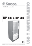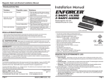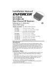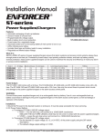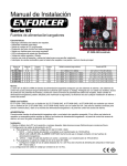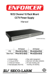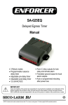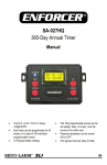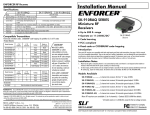
1
b. Action – If the TRG terminal is connected to (+) for the time set by the timer, the
relay activates and remains activated. To reset the latched relay, connect the TRG
terminal momentarily to (+) again.
c. Triggering by powering unit up – If DIP switch #5 is set to ON, the delay period set
by the timer starts when the SA-025Q is powered up. At the end of the delay period,
the relay latches on and remains on until the SA-025Q is disconnected from power.
5. Pulsing or Flashing Output, instant or delay (Fig. 6):
a. DIP switch settings:
1 – Relay output mode, see below
2 – Instant/delay start, see below
3 – OFF
ENFORCER
®
SA-025Q
Programmable Timer Module
4 – Timer setting (ON or OFF)
5 – OFF
6 – OFF
b. Action – If the TRG terminal is connected to (+) momentarily, the SA-025Q waits for
the time set by the timer, and then starts pulsing/flashing. The pulse/flash output lasts
until the TRG terminal is disconnected from (+).
c. Triggering by powering unit up – If DIP switch #5 is set to ON, the output works the
same, but instead of triggering via the TRG terminal, the SA-025Q is triggered by
being powering up.
d. Instant/delay start – If DIP switch #2 is set to ON, the SA-025Q waits for the time set
by the timer after triggered or powered up, and then starts pulsing/flashing. If DIP
switch #2 is set to OFF, the SA-025Q starts pulsing/flashing as soon as it is triggered
or powered up.
e. Relay output time – If DIP switch #1 is set to ON, the relay on and off time depends
on how the timer is set. If DIP switch #1 is set to OFF, the relay on time is fixed at
about 1 second, and the relay off time depends on how the timer is set.
6. Optional Negative Trigger or Closed-Circuit Trigger (Fig. 7):
If a closed-circuit negative trigger is required, it is necessary to install a 1K
(1,000-ohm) resistor as shown (included).
WARRANTY: This SECO-LARM product is warranted against defects in material and workmanship while used in normal
service for a period of one (1) year from the date of sale to the original consumer customer. SECO-LARM’s obligation is
limited to the repair or replacement of any defective part if the unit is returned, transportation prepaid, to SECO-LARM.
This Warranty is void if damage is caused by or attributed to acts of God, physical or electrical misuse or abuse, neglect,
repair, or alteration, improper or abnormal usage, or faulty installation, or if for any other reason SECO-LARM determines that
such equipment is not operating properly as a result of causes other than defects in material and workmanship.
The sole obligation of SECO-LARM, and the purchaser’s exclusive remedy, shall be limited to replacement or repair only, at
SECO-LARM’s option. In no event shall SECO-LARM be liable for any special, collateral, incidental, or consequential personal
or property damages of any kind to the purchaser or anyone else.
NOTICE: The information and specifications printed in this manual are current at the time of publication.
However, the SECO-LARM policy is one of continual development and improvement. For this reason, SECO-LARM
reserves the right to change specifications without notice. SECO-LARM is also not responsible for misprints or
typographical errors.
Copyright © 2007 SECO-LARM U.S.A., Inc. All rights reserved. This material may not be reproduced or copied, in
whole or in part, without the written permission of SECO-LARM.
SECO-LARM® U.S.A., Inc.
16842 Millikan Avenue, Irvine, CA 92606
Tel: 800-662-0800 / 949-261-2999 Fax: 949-261-7326
Installation Manual
file: D/DTP/MISA-025Q_074
MIA025.P65/FEB2003
Order Part #760-100-3/074
Website: www.seco-larm.com
E-mail: [email protected]
PITSW1
The SA-025Q Programmable Timer Module is suitable for a wide range of timed security
and access control operations, such as door unlock timing, siren or bell timer, VCR timer,
and so on. Auto-sensing of input voltage and DIP switches for programming make
installation easy.
Features / Specifications:
• Timer can be set from 1 second to 60 minutes
• Can be triggered via a N.O. positive (+) trigger input signal or a N.C. negative (-) trigger
device or by powering up the unit
• Relay can be programmed to activate at the start or at the end of the timing cycle
• Relay can also be set to activate for one second at the end of the timing cycle
• Relay can be programmed to pulse (flash) or be steady on
• Built-in reset function to manually reset timing cycle
• Form-C relay, contacts rated 8A @ 120VAC/24VDC
• LED indicates relay is energized
• 12VDC/24VDC operation (auto sensing)
• Current draw – Less than 1mA (standby) or 50mA (relay energized)
• Board measures 2-7/8” x 2-1/2” (73 x 63 mm)
• Functions programmed via DIP switches – no jumpers to cut
Wiring:
• TRG – N.O. Positive (+) trigger input
Fig. 1 – DIP switch settings
signal or
Switch Off
On
– N.C. Negative (-) trigger input
#1
Fixed 1 sec. Relay
Variable Relay output
signal (1K ohm resistor
output time
time
required - included)
#2
• (-) – Ground input
Relay energizes at start
Relay energizes at
of timing cycle
end of timing cycle
• (+) – +12VDC to +24VDC input
#3
REPEAT timing cycle
SINGLE timing cycle
• NO – Relay output (normally open)
#4
Time
in
MINUTES
Timing in SECONDS
• COM – Relay output (common)
#5
• NC – Relay output (normally closed)
Timing controlled by
Timing controlled by
DIP Switch Settings (Programming):
The SA-025Q is programmed via a
series of six DIP switches which can be
turned on or off. See fig. 1.
#6
-1-
TRG input
Power Up
Counter begin at START
of TRG
Counter begin at END
of TRG
Note: Products with model number that ends with "Q" or have a green “Q” sticker represents RoHS compliant products.
Setting the Timer:
The relay output time can be programmed for either 1 to 60 seconds, or 1 to 60 minutes,
using the round, black thumbwheel:
1. Determine and set DIP switch #4 according to whether the timing should be measured in
seconds or minutes (see DIP Switch Settings above).
2. Turn the thumbwheel on the SA-025Q clockwise to increase time, and counter-clockwise to
decrease time.
3. Test the time, and make adjustments as needed.
c. Triggering by powering unit up – If DIP switch #5 is set to ON, the output works the
same, but instead of triggering via the TRG terminal, the SA-025Q is triggered by
being powered up.
4. Latched Output, delayed (Fig. 5):
a. DIP switch settings:
1 – ON
2 – ON
3 – ON
4 – Timer setting (ON or OFF)
5 – OFF
6 – OFF
NOTE – You should carefully test the time period once it is set.
Sample Installations for Common Timer Applications:
Fig. 2 – Momentary trigger, no delay
Fig. 3 – Momentary trigger, no delay
Fig. 4 – 1-time mom. trigger, no delay
Fig. 5 – Latched output, delayed
Fig. 6 – Pulse/flash o/p, instant/delay
Fig. 7 – Optional negative or
closed-circuit trigger
NOTE – The following only represents a few of the many possible ways to use this Timer
Module. For your specific application, it may be necessary to experiment with the DIP
switch settings.
1. Momentary trigger, no delay (for timed annunciator or supervisory circuit) (Fig. 2):
a. DIP switch settings:
3 – ON
5 – OFF
1 – ON
4 – Timer setting (ON or OFF)
6 – OFF
2 – OFF
b. Action – If the TRG terminal is connected to (+) momentarily, the relay output
immediately turns on. The output stays on for the time set by the timer, after which it
turns off regardless of whether the trigger is connected or disconnected.
NOTE – If the momentary trigger time is less than the time set by the timer, the relay
output is triggered only once. If the trigger time is longer than the timer time, the relay
will be activated a second time when the trigger is removed.
c. N.O. vs. N.C. output – For a timed door annunciator, connect a buzzer or chime to
the N.O. and COM outputs. For a closed-loop supervisory circuit, connect a dialer or
transmitter to the N.C. and COM outputs.
2. Momentary trigger, no delay (for swinger eliminator) (Fig. 3):
a. DIP switch settings:
1 – ON
3 – ON
5 – OFF
2 – OFF
4 – Timer setting (ON or OFF)
6 – ON
b. Action – If the TRG terminal is connected to (+) momentarily, the relay output
immediately turns on, and stays on for as long as the TRG terminal is connected to
(+). Once the TRG connection is broken, the relay output remain activated for as long
as the time period set by the timer, and then turns off.
c. Triggering by powering unit up – If DIP switch #5 is set to ON, the output works the
same, but instead of triggering via the TRG terminal, the SA-025Q is triggered by
powering it up. Once powered up, the relay remains activated for the time set by the
timer, or until power is removed, whichever comes first.
3. One-time 1-sec. momentary trigger, no delay (Fig. 4):
a. DIP switch settings:
1 – OFF
3 – ON
5 – OFF
2 – OFF
4 – Timer setting (ON or OFF)
6 – ON
b. Action – If the TRG terminal is connected to (+) momentarily, the relay output
immediately activates for about one second. To reset the SA-025Q, the TRG must be
disconnected from (+) for at least two seconds. The timer has no effect.
-2-
*
*(1K ohm resistor included)
Note: regarding DIP switch #1:
DIP #1 setting
Sometimes DIP switch #1 will function as an
OFF
instant/delay control, but when it is ON, its actual
ON (DIP #3 ON)
function depends on how DIP switch #3 is set.
ON (DIP #3 OFF)
-3-
Function
1-sec. momentary relay output
Relay output latches on
Relay output equals 1 sec.