1
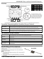
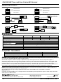
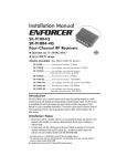
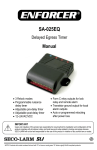
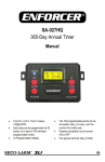
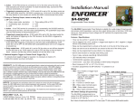
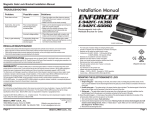
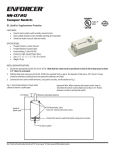
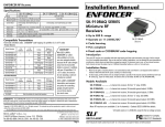
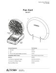
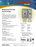
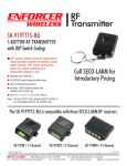
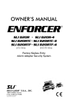
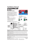
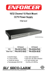
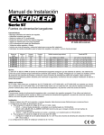
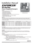
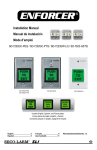
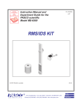
Installation Manual SK-910R3Q SK-910R3-4Q SK-910R4Q SK-910R4-4Q 3 Channels (315MHz) 3 Channels (433.92MHz) 4 Channels (315MHz) 4 Channels (433.92MHz) (SK-910R4Q pictured) Three- and Four-Channel RF Receivers Flexible operating voltage: 11~24 VAC/VDC Up to 500ft (152m) range Independently programmable channels Note: Products with model numbers that end with “Q” or that have a round green “Q” sticker are RoHS compliant. Also Available from SECO-LARM: SK-910RBQ ............................................................... One-channel receiver, 315MHz SK-910RLQ ........................................... Low-voltage, one-channel receiver, 315MHz SK-910RVQ ......................................................... Low-voltage, one-channel receiver, transistor ground output 315MHZ SK-910R-4Q ......................................................... One-channel receiver, 433.92MHz SK-910RL-4Q ................................... Low-voltage, one-channel receiver, 433.92MHz SK-910RV-4Q ...................................................... Low-voltage, one-channel receiver, transistor ground output, 433.92MHz SK-910RB2Q ............................................................. Two-channel receiver, 315MHz SK-910RB2-4Q ..................................................... Two-channel receiver, 433.92MHz This manual covers only the three- and four-channel receivers. For information on all other receivers, please contact SECO-LARM. Introduction: The SK-910R3Q and SK-910R4Q are wireless receivers that meet the growing demand for multi-channel receivers with multiple and independently controlled output modes. RF receivers can be used to control a variety of home automation devices such as garage door openers, lights, motorized gates, lifts, or other devices remotely. These receivers are compatible with both fixed code and code hopping transmitters. Code hopping transmitters, such as SECO-LARM CODEBUMP™ transmitters, change codes every time transmitter sends a signal for extra security. See page 4 of this manual for a list of compatible transmitters. Installation Notes: 1. Mount the receiver out of sight in a location where it is not exposed to the weather or moisture, and where it is not surrounded by metal. Metal will block the RF signal, resulting in a reduced range. 2. For best range, pull the antenna wire as long and straight as possible. If the receiver receives interference from local RF activity (e.g., an airport or military base), the antenna wire can be folded. DO NOT CUT THE ANTENNA WIRE. ENFORCER Three- and Four-Channel RF Receiver Code Learning a New Transmitter Button: Each receiver channel can learn the codes of up to 15 different transmitters on a first-in, first-out basis. Below is the procedure for code learning a new transmitter button. The same procedure applies to each of the receiver’s channels. 1. Press the transmitter programming button of the desired channel to be programmed for 3 seconds or more. The channel’s LED will start to flash quickly to indicate that it is in the learning mode. 2. While the LED is flashing, press the button of the transmitter to be learned once. The LED will flash once to indicate a successful learning of that button’s code. After the button has been learned, the receiver will automatically exit the learning mode. Repeat step 1 to re-enter the learning mode. NOTE: The transmitter programming buttons can be found at the rear of the receiver’s case. The button number corresponds with the channel number. For example, button #1 is the programming button for channel 1. The channel’s LED will flash for a maximum of 15 seconds. If no transmitter button is pressed during this time, the receiver will exit the code-learning mode, and the LED will turn off. If the code being learned has already been learned, the LED for the channel which learned the code will turn steady ON and then start flashing again. The code will not be learned a second time. Each channel can learn the codes of a maximum of 15 transmitter buttons. If you attempt to learn a sixteenth transmitter code, the earliest code will be deleted. Clear Channel Memory: To clear all codes in the channel’s memory, press the transmitter programming button for that channel for 3 seconds or more until the LED flashes. Release, and then press that button again for 3 seconds or more until the LED stops flashing. The LED will then flash twice to indicate that all codes associated with that channel have been deleted. Display Channel Memory: To see how many codes have been learned in a channel, press that channel’s transmitter programming button once. The number of codes stored in the channel’s memory is equal to the number of LED flashes. Programming Each Channel Relay Output Mode: Each receiver channel can be programmed for one of five different modes, and each individual channel may operate at a different output mode, depending on the user’s application. The five modes are: 1. Timed Output – Press the transmitter button once. The timed output relay will activate from 1~60 seconds, depending on the set output time. See page 3 for information on programming the output time. (DEFAULT: 1 second timed output) 2. Toggle Output – Works much like a toggle switch to turn a device ON & OFF alternately. Press the transmitter button once, and the relay turns ON. Press the transmitter button again, and the relay turns OFF. 3. Latch Output – Press the transmitter button once, and the relay turns ON and stays ON. The relay will remain ON until the appropriate channel’s transmitter programming button is pressed once to reset, regardless of whether a compatible transmitter button is pressed again or not. 4. Validity Output – The channel will turn the relay ON for as long as the transmitter button is pressed. NOTE: Due to possible interference or drops in transmitter battery power while the transmitter button is continuously pressed (even for short periods of time), the receiver may lose the transmitter’s signal and turn the relay OFF. Press the programming mode switch once to program a channel’s output mode. That channel’s LED will flash a number of times equal to the output mode that it is in. To change modes, press the desired channel’s mode button. Each press moves to the next mode in the sequence shown in the diagram to the right. After changing modes, count the number of times the channel LED flashes to verify the channel is in the correct mode. The programming procedure for each channel is the same. To exit programming, press the programming mode switch again. 2 Toggle Output (2 flashes) Timed Output (1 flash) Latch Output (3 flashes) Validity Output (4 flashes) NOTE: For a diagram of the PC board, including the location of the mode buttons, please see Overview, page 3. SECO-LARM U.S.A., Inc. ENFORCER Three- and Four-Channel RF Receiver Overview: CH 3 Mode switch CH 2 Mode switch CH 1 Mode switch CH 4 Mode switch (4-Channel models only) Programming mode switch Time programming DIP switch Power Input 11~24 VAC/VDC Channel 1 Channel 2 Sec. 1 2 3 4 5 10 30 60 SW1 On Off Off On Off On Off On SW2 Off On Off Off On On Off On SW3 Off Off On On On Off Off On If an optional antenna is used, LP3 must be cut and the antenna slot on the receiver case must be chipped off to accommodate the extended range antenna wire. Status LED Channel 4 (4-Channel models only) Channel 3 (PC Board shown. Remove the front cover of the receiver to access the mode buttons and terminal block.) Transmitter Programming Button Operation (One per Channel): Learn mode Clear memory Reset latched output Memory display Press and hold the transmitter programming button for three seconds or more. Press and hold the transmitter programming button for three seconds or more, then when the LED starts flashing, press again for three seconds to delete all previously learned codes. If this channel was programmed for latch output, once the relay is turned ON with a transmitter button, press the transmitter programming button of that channel once to turn the relay OFF. Press and release the transmitter programming button to show the number of codes stored. The LED will flash a number of times corresponding to the number of codes stored. LED Indication (One per Channel): Steady ON Fast flash One flash Two flashes Three flashes Four flashes 0~15 flashes Senses signal from a transmitter button in normal operation, or indicates a transmitter button’s code already exists in the receiver’s memory during code learning. In the code-learning mode or channel memory display mode, or during the programming channel output mode. A transmitter button code was learned, or the relay is in timed output mode. All previously learned transmitter buttons were deleted, or the relay is in toggle output mode. Latch output. Validity output. In the normal operation mode, pressing the channel mode button once will display the number of codes learned. Extended Range Antenna (Optional): Extends RF receiver range up to 1,000ft (304m) (open air) with existing remotes. Comes with a 9ft cable that easily plugs into the 3-pin antenna port located on the RF receiver. NOTE: If an extended range antenna is used, the “LP3” on the receiver PC board must be cut. Actual antenna range will vary greatly depending on the operating environment. SECO-LARM U.S.A., Inc. SK-91ERSD 3 ENFORCER Three- and Four-Channel RF Receiver Sample Applications: Negative Output Positive Output COM NC NO Positive Power Source — + Negative Power Output — + Power for receiver Power for receiver Typical N.O. Application Typical N.C. Application COM NC NO SD-996C-NUQ Electric Door Strike COM NC NO E-941SA-1200 Electromagnetic Lock — + — + N.C. Application with Independent Power Sources N.O. Application with Independent Power Sources DC Power Source COM NC NO — + Negative Power Source COM NC NO Positive Power Output AC Power Source DC Power Source COM NC NO — + E-941SA-1200 Electromagnetic Lock AC Power Source SD-996C-NUQ Electric Door Strike Specifications: Model Operating frequency Number of channels Memory capacity Operating voltage Operating current SK-910R3Q 315MHz 3 Standby Active Relay contact rating Connectors Dimensions SK-910R3-4Q SK-910R4Q SK-910R4-4Q 433.92MHz 315MHz 433.92MHz 3 4 4 15 transmitter button codes per channel 11~24 VAC/VDC 12mA@12VDC 50mA@12VDC per channel Form C 10A@24VDC or 120VAC per channel Screw terminals, +, -, with NO/NC/COM per channel 5.3”x3.9”x1.1” (135x100x27.5mm) Compatible Transmitters: Operating frequency Fixed Code: 68 billion codes CODEBUMP™: 18 quintillion (1.8x10¹⁹) codes 315MHz SK-919 Series Fixed Code SK-917 Series CODEBUMP 433.92MHz SK-939 Series Fixed Code SK-937 Series CODEBUMP WARRANTY This SECO-LARM product is warranted against defects in material and workmanship while used in normal service for a period of one (1) year from the date of sale to the original consumer customer. SECO-LARM’s obligation is limited to the repair or replacement of any defective part if the unit is returned, transportation prepaid, to SECO-LARM. This Warranty is void if damage is caused by or attributed to acts of God, physical or electrical misuse or abuse, neglect, repair, or alteration, improper or abnormal usage, or faulty installation, or if for any other reason SECO-LARM determines that such equipment is not operating properly as a result of causes other than defects in material and workmanship. The sole obligation of SECO-LARM, and the purchaser’s exclusive remedy, shall be limited to replacement or repair only, at SECO-LARM’s option. In no event shall SECO-LARM be liable for any special, collateral, incidental, or consequential personal or property damages of any kind to the purchaser or anyone else. NOTICE: The information and specifications printed in this manual are current at the time of publication. However, the SECO-LARM policy is one of continual development and improvement. For this reason, SECO-LARM reserves the right to change specifications without notice. SECO-LARM is also not responsible for misprints or typographical errors. Copyright © 2012 SECO-LARM U.S.A., Inc. All rights reserved. This material may not be reproduced or copied, in whole or in part, without the written permission of SECO-LARM. U.S.A., Inc. 16842 Millikan Avenue, Irvine, CA 92606 Tel: 800-662-0800 / 949-261-2999 Fax: 949-261-7326 4 Website: www seco-larm.com E-mail: [email protected] PITSW1 MiSK-910R3Q_SK-910R4Q_1204.docx SECO-LARM U.S.A., Inc.